AMI BIOS汇总
AMI Bios 设置全程图解

Advanced
USB Configuraion(USB装置设置)
USB Function [x USB ports] USB端口开启个数
Legacy USB support [auto] USB端口自动检测设置
USB 2.0 Controller [Enabled] USB控制器开关
DDR Reference Voltage [Auto] 内存电压设置
AGP VDDQ Voltage [1.50V] AGP设备电压设置
configure advanced CPU settings (CPU信息)
Manufacturer:xxxxxxx 品牌
configure system frequency/voitage
AI Overclock tuner 智能CPU频率设置
performance Mode 增强型模式
选项
Manual 手动设置
Standard 标准模式
Overclock 5% 步进超频
Configure System Frequency/Voltage
Power
Hardware Monitor(系统监控)
CPU Temperature [xx℃/xxx'F] CPU温度
MB Temperature [xx℃/xxx'F] 系统温度
Power Temperature [N/A] 电源温度
ICH Delayed Transaction [Enabled] ICH延时控制
MPS Revision [1.1] MPS修正
Onboard AC'97 Audio [auto] 声卡设定
最全面的AMI BIOS设置图解教程
最全面的AMI BIOS设置图解教程开机显卡自检测完成后,点击<DEL键>即可进入AMI BIOS SETUP设置界面主菜单。
进入了AMI BIOS NEW SETUP UTILITY 设定工具, 屏幕上会显示主菜单。
主菜单共提供了十二种设定功能和两种退出选择。
用户可通过方向键选择功能项目, 按键可进入子菜单。
默认设置BIOS setup程序有两种默认的设置:BIOS Setup设置和High Performance Defaults设置。
BIOS Setup Defaults设置提供了所有设备和系统的稳定但最小效能的设置。
而High Performance Defaults设置提供了最好的系统效能,但有可能导致系统不稳定。
Standard CMOS Features(标准CMOS设定)使用此菜单可对基本的系统配置进行设定。
如时间,日期等。
Advanced BIOS Features(Advanced Chipset Features(Power Management Features(PNP/PCI ConfigurationsIntegrated PeripheralsPC Health StatusFrequency/Voltage ControlSet Supervisor PasswordSet User PasswordLoad High Performance DefaultsLoad BIOS Setup DefaultsSave & Exit SetupExit Without Saving(不保存退出)放弃对CMOS的修改,然后退出Setup程序。
(保存后退出)保存对CMOS的修改,然后退出Setup程序。
(载入BIOS设定值缺省值)使用此菜单可以加载主板制造商提供的最小稳定的方式运行设置的一组默认值。
(载入高性能缺省值)使用此菜单可以加载主板制造商提供的为较高的性能优化过的BIOS设定值。
AMIBIOS模块结构详解完整版

AMIBIOS模块结构详解完整版AMI BIOS模块结构详解完整版首先在讲AMI BIOS模块结构前,需要向大家说一样东西,就是逻辑地址.逻辑地址的形式如:XXXX:XXXX,其中前四位是段地址,后四位是偏移地址,比如ABCD:1234 物理地址=段地址*10H+偏移地址所以ABCD:1234的物理地址=ABCDH*10H+1234H=ACF04H 而ACF04H这个物理地址是相对于1M噶地址空间的如果你的BIOS大小是1M噶话那么物理地址就是ACF04H如果BIOS不是1M的话那么就要对物理地址进行换算好有条公式: BIOS文件在WINHEX中的地址 = BIOS文件相对于1M空间的地址- 常数,注:常数是根据每个BIOS的大小而确定的常数=(1024-你BIOS的大小(KB))*1024.比如你的BIOS是512KB的话那么常数就是常数=(1024-512)*1024=524288D=80000H所以ABCD:1234在512KB的BIOS中 BIOS文件在WINHEX中的地址就=ABCDH*10H+1234H-80000H=2CF04HOK 现在各位应该明白逻辑地址转化为物理地址的方法了用WINHEX打开AMI BIOS可以搜索到AMIBIOSC的字符串这里隐含很多秘密如下:(这个BIOS 512KB的)用WINHEX打开AMI BIOS可以搜索到AMIBIOSC的字符串这里隐含很多秘密.如下:(这个BIOS 512KB的)Offset 0 1 2 3 4 5 6 7 8 9 A B C D E F00067FE0 00 00 00 00 00 00 00 00 08 0A 41 4D 49 42 494F ..........AMIBIO00067FF0 53 43 30 38 30 30 06 CE 21 40 BC 75 0C 00 83 E7 SC0800.?@紆..冪这里一共20H具体结构如下:0-2H 保留供将来使用3H 一般都是00 如果不是00的话发BIOS给我4-5H BIOS映像版本8H 都是08的9H 都是0A的 (AMIBIOSC08的长度)A-13H AMIBIOSC14-17H BIOS 核心版本18-1BH BIOS校验位1C-1DH 第一个模块的偏移地址1E-1FH 第一个模块的段地址由此可知在这个BIOS里面第一个模块的逻辑地址是 E783:000C 所以物理地址=E7830H+000CH-80000H=6783CH6783CH-8H就是第一个模块的地址了至于为什么要-8H 你自己看一下就知道了OK 第一个模块的地址找到了继续研究一下第一个模块的头部看看有什么秘密Offset 0 1 2 3 4 5 6 7 8 9 A B C D E F 00067830 00 FF FF FF 98 07 00 00 F3 C3 B9 AA 10 00 1B E2 00067840 98 07 08 80 00 00 00 00 01 00 0C 00 20 35 01 00其中红色部分的14H就是模块头了单独提取出来Offset 0 1 2 3 4 5 6 7 8 9 A B C D E F 00000000 98 07 00 00 F3 C3 B9 AA 10 00 1B E2 98 07 08 80 00000010 00 00 00 00 0-3H 模块大小4-7H 校验位8-9H 下一个模块的偏移地址A-BH 下一个模块的段地址C-DH 模块大小EH 模块IDFH 模块属性由此可知该模块的模块大小是0798H 校验位AAB9C3F3 下一个模块的地址为E21B:0010 模块ID为08从此可以得知下一个模块的位置如此类推......................直到最后一个模块Offset 0 1 2 3 4 5 6 7 8 9 A B C D E F00000FD0 44 00 00 00 92 9F 03 15 FF FF FF FF 44 00 80 80 00000FE0 00 00 00 00 07 00 10 02 01 00 00 14 00 20 08 01 红色的就是模块头最后一个模块的模块头的8-BH都是FF FF FF FF的表示是最后一个模块了OK AMI BIOS模块机构详解到此完毕。
amibios设置全程图解(AM...
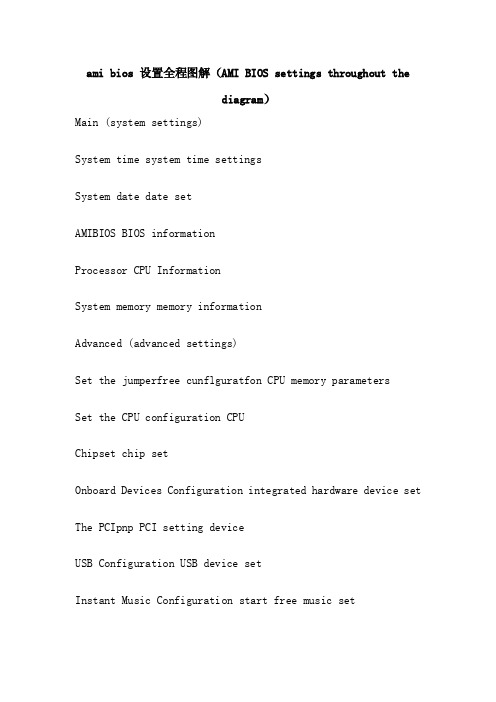
ami bios 设置全程图解(AMI BIOS settings throughout thediagram)Main (system settings)System time system time settingsSystem date date setAMIBIOS BIOS informationProcessor CPU InformationSystem memory memory informationAdvanced (advanced settings)Set the jumperfree cunflguratfon CPU memory parametersSet the CPU configuration CPUChipset chip setOnboard Devices Configuration integrated hardware device set The PCIpnp PCI setting deviceUSB Configuration USB device setInstant Music Configuration start free music setConfigure system frequency/voitageAI Overclock tuner CPU intelligent frequency settingPerformance Mode enhanced modeloptionSet manual ManualStandard standard modeOverclock 5% step overclockingConfigure System Frequency/VoltageCPU External Frequency {MHz} [xxxx] CPU FSB setDRAM Frequency [Auto] memory frequency settingsAGP/PCI Frequency {MHz} [Auto]AGP/PCI frequency setting equipmentCPU VCore Voltage [Auto] CPU core voltage settingsDDR Reference Voltage [Auto] memory voltage settingsAGP VDDQ Voltage [1.50V] AGP voltage equipment setConfigure advanced CPU settings (CPU)Manufacturer:xxxxxxx brandBrand String:xxxxxxx CPU informationFrequency: the CPU running at xxxxxxMHzFSB Speed: xxxxxxMHz CPU front busCache L1:xxxxxxxxxKB cacheCache L2:xxxxxxxxxKB two level cacheCache L3:xxxxxxxxxKB three level cacheMax CPUUID Value Limit [Disabld] CPU switchCPU Enhanced C1 Cintrol [auto] enhanced control switchCPU Internal Thermal Control [auto] CPU internal temperature control switchHyper Threading Technology [Enabled] CPU hyperthreaded switchAdvanced (Advanced chipset setup)Advanced Chipset SettingsConfigure DRAM Timing by SPD [Enablde] SDRAM clock setMemory Acceleration Mode [auto] memory acceleration controlDRAM Idle Timer [auto] memory free controlDRAM Refresh Rate [auto] memory update controlGraphic Adapter Priority [AGP/PCI] AGP/PCI priority settingsGraphics Aperture Size [xxxxMB] AGP graphics card memory settingsSpread Spectrum enhanced [Enabled] spectraICH Delayed Transaction [Enabled] ICH delay controlMPS Revision [1.1] MPS correctionOnboard AC'97 Audio [auto] sound card set板载LAN [启用]网卡设定板载网卡启动ROM ROM开关网卡[禁用]串行端口地址[ 3F8 / IRQ4 COM1序列地址]串行端口地址[ 2F8 / IrQ3型] COM2序列地址并行端口地址[禁用]井口序列地址板载游戏/ MIDI端口[禁用]游戏摇杆接口设定先进的先进的PCI / PNP设置(PCI设备设置)即插即用的O / S的[没有] PCI端口系统识别控制PCI延迟定时器[XX] PCI延时设置分配IRQ的PCI VGA [是]显卡中断位置设置PCI IRQ调色板窥探[禁用]特殊非标准显卡设置PCO IDE总线主控[启用] PCI IDE装置控制读写先进的USB(USB装置设置)配置USB功能的USB端口的USB端口开启个数[×]usb支持USB端口自动检测设置[汽车]USB 2控制器的USB控制器开关[启用]USB 2控制器模式[将] USB传输模式USB海量存储设备的配置大型存储装置设定功率(系统电源管理)挂起模式[汽车]系统省电设置reppost视频S3恢复[没有]唤醒系统时是否显示VGA画面支持ACPI 2 [没有] acpi2.0支持设置ACPI APIC支持[启用]是否增加ACPI APIC到rsdt清单、APM配置高级电源设置硬件监测上的系统监控功率APM的配置(高级电源设置)电源管理/ APM [启用]是否开启电源进阶管理与功能视频省电模式[禁用]是否在视频停止后进入省电模式硬盘电源关闭模式[禁用]是否在硬盘停转后进入省电模式暂停时间[禁用]进入省电模式的时间油门慢时钟率××%系统进入省电模式的运行速度[ ]电源键模式[开关]按关机键是进入休眠模式还是关机在交流电源的损失[关机]断电后再开启恢复断电前状态恢复电由RTC报警[禁用]自动定时唤醒设置电源由外部调制解调器[禁用]远程唤醒设置电源的PCI设备的PCI设备唤醒设置[禁用] 在PS / 2键盘[禁用]键盘唤醒设置功率在PS / 2鼠标[禁用]鼠标唤醒设置功率功率硬件监控(系统监控)CPU温度[ XX℃/ xxx'f ] CPU温度MB温度[ XX℃/ xxx'f ]系统温度功率温度[ / ]电源温度风扇速度调整Q-FAN控制[禁用]CPU风扇转速xxxxrpm CPU风扇转速[ ]机箱风扇转速[ / ]机箱风扇转速电源风扇转速[ / ]电源风扇转速Vcore电压[性质]电压监控3.3V电压[性质]电压监控5V电压[性质]电压监控[性质]电压监控12V电压靴子启动设置(启动选单)启动设备优先级启动装置顺序可移动驱动器移动装置顺序光盘驱动器光驱启动顺序启动设置配置启动选项设定安全安全性选项启动启动设备优先级(启动设备顺序)第一启动设备[3M迈拓]第一启动盘第二启动设备[禁用]第二启动盘启动设置启动项(启动选项设置)快速启动[启用]快速启动设置全屏标志[启用]开机画面设置插件ROM BIOS显示模式[力]附件装置软件显示模式Num Lock小键盘锁定设置启动[上]PS / 2鼠标支持[汽车] PS / 2鼠标开关击键速度键盘反映频率设置[快速]启动OS / 2 [不] OS / 2系统设置等待“F1”如果错误[启用]错误信息提示设置点击“删除”消息显示[启用]按下del指示提示设置中断19捕获[禁用] PCI内键程序启动设置启动安全设置(系统安全设定)dupervlsor系统管理员密码设定更改密码引导扇区病毒保护[禁用]防病毒保护开关出口退出选项(退出BIOS程序设置)退出并保存更改退出并保存设置退出和放弃改变退出而放弃设置Discard Changes give up set but not quit the BIOS programLoad Setup Defaults according to factory settings((((A.Main (standard set)This menu is available on the basic system configuration settings. Such as time, date etc.amongPrimary/Secondary IDE Master/Slave is a device from the main IDE.If your motherboard supports SATA interface will haveThird/Fourth IDE Mastert or more, they are all inside the computer management cases of IDE driving device, such as a hard disk, CD-ROM etc.! Because each motherboard is different, so this is not a detailed explanation of the set, but the general users do not have to use the default settings, the general can, if there are special requirements, it is recommended that users control instructions that are set up in the forum, or separate questions!System InformationThis is the basic hardware information display system, not what good (Figure 3)Understand the basic settings after entering the advanced settings!Two.Advanced (advanced settings) as shown in figure 4:Here is the core of Bios is set, the novice must be carefully set, because of the direct relationship between the stability of the system and the safety of the hardware, do not blindly set!1. we first see is the "JumperFree Configuration" (different brands of the motherboard may be different, there may be no longer) here can set some parameters of CPU, for the love of friends here is the main overclocking! (Figure)You can see a "AI Overclock Tumer" option, in which there are some options, as shown above, the "Manual" as the key, you will see the following chart selection:For CPU overclocking enthusiasts these things should be well known, CPU (CPU External Frequency) the FSB set is one of the key of overclocking, CPU frequency (i.e. within we usually said P4 3.0G frequency) is multiplied by the value of frequency and frequency, such as a 3.0G CPU in the FSB is 200 time of his frequency is 15 (200MHz*15 = 3000MHz). The range can be set for general FSB 100MHz to 400MHz, but the real 300 CPU are not many, so do not blindly set high FSB, a general setting range is about 100-250 about users set to have a little bit of heightening patient, it is best to 1MHz step, plus a little bit, to to prevent excessive one-time system cannot be used normally oreven damage CPU!Memory frequency setting (DRAM Frequency) using this set of installed memory clock, set the options: 200MHz, 266MHz, 333MHz, 400MHz, Auto.AGP/PCI (AGP/PCI Frequency), the frequency setting operation frequency of this project can modify the AGP/PCI equipment, in order to obtain better system performance and overclocking performance, setting value: [Auto], [66.66/33.33],[72.73/36.36]. But please set the appropriate user, if improper setting may cause AGP/PCI equipment can not be used normally!Needless to say the voltage setting,Is the working voltage setting device, recommended for most users do not easily modify, so as to prevent damage to the unit because the voltage is not correct! Is the user to modify must not blindly, to step the way a little bit of pressure, the maximum value should not exceed 0.3V.2. CPU Configuration (CPU) of this project can let you know the related index of CPU and change CPU.Here you can get all kinds of information CPU, because this is the latest ASUS Bios program, so it increased the number of new CPU information, such as the three level cache, and adds to the enhanced options Intel64 CPU! But these projects for the general CPU is not what meaning! Some of the options here basically don't change, but here is the most meaningful option is the last Hyper Threading Technology option, which isswitched on P4 CPU hyper threading, hyper threading CPU with P4 user should know that some programs can not well support hyper threading technology, and sometimes even lead to crashes, such as the Internet WinXP SP1 IE P4 hyperthreaded users have frequent crashes the CPU occupancy rate of 100%, this is because it cannot fully support hyper threading technology (but as long as the update to the SP2 update or upgrade the system without this problem.) then we can close the hyper threading technology CPU, as long as the value of the can be set to Disabled! But this will not be able to fully play the performance of P4 hyper threading CPU!3. Chipset (Advanced chipset features) using this menu you can modify the chipset registers, the performance optimization system.Configure SDRAM Timing bySetting determines whether the SDRAM clock is set by reading the memory module of SPD (SerialPresence Detect) EEPROM content. According to the SPD set to Enabled will automatically set the project, if you have the option not to Disabled, will appear the following items: SDRAM CAS# Latency, DRAM RAS Precharge, DRAM RAS to CAS Delay DRAM, precharge Delay and DRAM Burst Length. If you are not familiar with these settings do not modify the chip group.SDRAM CAS# Latency (SDRAM CAS# delay)Control and accept the start delay time after read command in SDRAM (in clock cycles). Set value: 2, 2.5, 3 (clocks). Thesmaller the value of the more powerful performance! But the relative decline of stability!DRAM RAS Precharge (Precharge command delay)The project control when SDREM sends a Precharge command, how much time will no longer send command. Set value: 4, 3, 2 (clocks)RAS to CAS Delay (delay RAS to CAS)When DRAM refresh after all ranks to separate addressing. This setting allows you to decide from RAS (row address filtering) conversion to CAS (column address filtering) delay time. A smaller clock cycle will make DRAM performance faster. Set value: 4, 3, 2 (clocks)DRAM precharge Delay (pulse cycle)This setting is used to control for SDRAM clock cycle using SDRAM parameters! Set value: 8, 7, 6, 5 (clocks)SDRAM Burst Length (SDRAM access burst length)This setting allows you to set the length of the size of the outbreak of DRAM access. The outbreak is characterized in that the DRAM forecast their location of each memory access technology in the first address. Using this feature, you must define the burst length, is the beginning of the actual length of the pulse burst. At the same time allows the internal address counter can correctly generate the next address location. Thelarger the size of memory more quickly. Setting: 4, 8 (clocks).AGP Aperture Size (AGP memory allocation)This system is used to control the number of memory can be allocated to the AGP display card. The aperture is used for graphics memory address space of a part of the PCI memory address range. Enter the aperture within the scope of the master clock cycle will be translated directly to AGP. Setting: 4MB, 8MB, 16MB, 32MB, 64MB, 128MB, and MB 256.4.OnBoard Devices Configuration (integrated equipment set)Here are some options to manage a variety of integrated motherboard hardware facilities, users basically do not change the settings! This is no longer so paralepsis! Such as the need to change, please check the motherboard manual!5.PCI Pnp (plug and play device settings)Here is the setting plug project advanced settings and PCI, users do not need to change any item, you can keep the default. In this set, incorrect values will lead to damage to the system!B Configuration (USB device)USB port device settings, everyone can understand, no need to say more! Only the transmission mode which has a FullSpeed and HiSpeed, if we USB2.0 it is set to HiSpeed, FullSpeed is a simulation of high speed transmission, no HiSpeed fast!Three.Power (power management settings) figure:In front of four without what good talk, because the motherboard brand is different, so there may be some users do not have the above options, including APM Configuration (advanced power setting) and Hardware Monitor (monitoring system) two options.1. APM Configuration (advanced power setting)2.Hardware Monitor (monitoring system)Four.Boot (boot device)This menu is to change the system boot device and related settings, are more important in Bios.1. Boot Device Priority (boot device)This project is set to start when the system starts the memory order, such as we have to start from the CD-ROM during installation of the operating system, we must take the 1st Device Priority is set to become your CD-ROM, figure is arranged on the hard disk, so when the system boots the first startup is hard, if not to suggest that you start from the CD-ROM. The first startup settings become hard disk, other startup items set to Disable, this system will start relatively quickly, because the system not to search for other redundant hardware device!TwoBoot Settings Configuration (startup options)Here are some of the startup project settings system! It is convenient for users to better habits and improve the system performance.1. QuickBoot (quick start set)This project can set whether the computer self-test function at startup, and to accelerate the speed of system, if set to "Disable" system will be in the implementation of all self boot time, but it will start slowing down! The general setting is Enabled"2. Full Screen Logo (fulllogo display settings)Here is the set whether to open the boot Logo settings, if you don't want to boot Logo can be set to Disable"3. Add On ROM Display Mode (accessory software display)This project is the accessory device software allows you to set the display mode, the general is set to "Force BIOS" on it.4. Bootup NunLock (keypad lock switch)Is to set the boot is automatically opened on the keypad NumLock. General settings for On5. PS/2 Mouse SupportSet whether the PS/2 mouse support function of this project. Can be set to AUTO.6. Typematic Rate (keyboard settings reflect the frequency)This is to let you choose the keyboard to reflect the speed of frequency options, usually set to "fast"7. Boot To OS/2 (OS/2 system)This project allows you to choose whether to activate the OS/2 operating system compatibility mode, generally set to No"8. Wait For "F1" If Error (ErrorMessage)This project is set if an error occurs when the system starts to display press the "F1" button to confirm to continue the boot, usually set to "Enabled"9. Hit "DEL" Messgae Display (press DEL prompt)This option is displayed by pressing the Del key to enter Bios setup tips at boot time, if you choose "Disable" will not see this article at the beginning of the sentence "Press DEL to Run Steup, Presss TAB to display BIOS Post Message" message, usually set to "Enabled"10. Interrupt 19 Capture (PCI built in program startup settings)When the card comes with software you use PCI when you set thisto "Enabled"3. Security (safety performance options)1.Change Supervisor Password (administrator password)The administrator password set, when setting the password after several options, including a "User Password" option, which is the user password settings, like the Windows user password, they can be set into a variety of different access rights (Use Access Level), whichNo Access users to store Bios settingsView Only users can only view Bios settings cannot change settingsLimited allows the user to change the settingsFull Access users can change Bios settingsThere are several common optionsClear User Password clear password更改密码密码检查2。
AMIBios设置全程图解
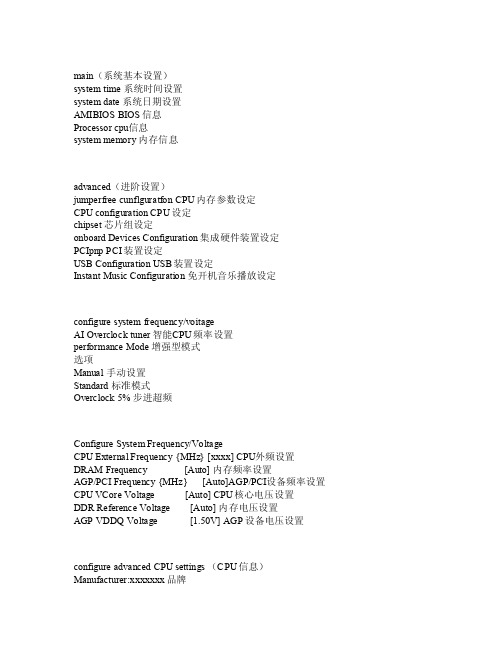
main(系统基本设置)sy stemtime系统时间设置sys tem d ate 系统日期设置AMIB IOS B IOS信息Proc essor cpu信息sys tem m emory内存信息a dvanc ed(进阶设置)j umper freecunfl gurat fon C PU内存参数设定C PU co nfigu ratio n CPU设定ch ipset芯片组设定onb oardDevic es Co nfigu ratio n 集成硬件装置设定PCIp np PC I装置设定USBConfi gurat ion U SB装置设定Ins tantMusic Conf igura tion免开机音乐播放设定co nfigu re sy stemfrequ ency/voita geAI Over clock tune r 智能C PU频率设置per forma nce M ode 增强型模式选项Ma nual手动设置Stand ard 标准模式O vercl ock 5% 步进超频Confi gureSyste m Fre quenc y/Vol tageCPU E xtern al Fr equen cy {M Hz} [xxxx] CPU外频设置D RAM F reque ncy [A uto]内存频率设置AGP/PCIFrequ ency{MHz} [Aut o]AGP/PCI设备频率设置CPUVCore Volt age [Auto] CPU核心电压设置DDR Refe rence Volt age [Aut o] 内存电压设置AGP V DDQ V oltag e [1.50V] AGP设备电压设置confi gureadvan ced C PU se tting s (CP U信息)Manuf actur er:xx xxxxx品牌B randStrin g:xxx xxxxCPU型号信息Fr equen cy :x xxxxx MHz C PU运行主频FSB Spee d :xx xxxxM Hz CP U 前端总线Ca che L1:xxx xxxxx xKB 一级缓存C acheL2:xx xxxxx xxKB二级缓存Cache L3:x xxxxx xxxKB三级缓存Max CPUU ID Va lue L imit [Dis abld] CPU开关Enh anced C1 C intro l [aut o] 增强型CPU控制开关C PU In terna l The rmalContr ol [a uto]CPU内部温控开关Hyper Thre ading Tech nolog y [Enabl ed] C PU超线程开关Advan ced(高级芯片组设置)Ad vance d Chi psetSetti ngsConfi gureDRAMTimin g bySPD [Enabl de] S DRAM的时钟设置Memor y Acc elera tionMode[auto]内存加速控制DR AM Id le Ti mer [au to] 内存空闲控制DRAM Refr esh R ate [auto] 内存更新控制Graph ic Ad apter Prio rity[AGP/P CI] A GP/PC I优先设定Grap hicsApert ure S ize [xxxx MB] A GP显卡内存设置S pread Spec trum [E nable d] 增强光谱I CH De layed Tran sacti on [E nable d] IC H延时控制MPS Revi sion [1.1] MPS修正Onboa rd AC'97 A udio[auto]声卡设定Onbo ard L AN [Enab led]网卡设定Onboa rd LA N Boo t ROM[Disab led]网卡ROM开关S erial port1 Add ress [3F8/IR Q4] C OM1序列地址Se rialport2 Addr ess [2F8/IRQ3] CO M2序列地址Par allel Port Addr ess [Dis abled] 井口序列地址O nBoar d Gam e/MID I por t [D isabl ed] 游戏摇杆接口设定Adva ncedAdvan ced P CI/Pn P set tings(PCI设备设置)plug andplayo/s [NO]PCI端口系统识别控制PCI Late ncy T imer [xx] PCI延时设置A lloca te IR Q toPCI V GA [Y es] P CI显卡I RQ中断位置设置P alett e Sno oping [D isabl ed] 特殊非标准显卡设置P CO ID E Bus Maste r [E nable d] PC I读写ID E装置控制Ad vance dUSB Conf igura ion(U SB装置设置)U SB Fu nctio n [x USBports] USB端口开启个数Leg acy U SB su pport [aut o] US B端口自动检测设置USB 2.0 Co ntrol ler [Enabl ed] U SB控制器开关US B 2.0 Cont rolle r Mod e [HI Speed] USB传输模式USBMassStora ge De viceConfi gurat ion 大型存储装置设定Powe r(系统电源管理)Suspe nd Mo de [Auto]系统省电设置Re ppost Vide o onS3 Re sume [no] 唤醒系统时是否显示VGA画面ACP I 2.0 Supp ort [no] ACPI2.0支持设置AC PI AP IC su pport [En abled] 是否增加ACPI APIC到RSDT清单、APM C onfig urati on 高级电源设置Hardw are M onlto r 系统监控PowerAPMConfi gurat ion(高级电源设置)Po wer M anage mcnt/APM [En abled] 是否开启电源进阶管理AMP功能Vi deo P owerDownMode [Di sable d] 是否在视频停止后进入省电模式Ha rd Di sk Po wer D own M ode [Di sable d] 是否在硬盘停转后进入省电模式Su spend Time Out [Di sable d] 进入省电模式的时间Th rottl e Slo w Clo ck Ra tio [xx%] 系统进入省电模式的运行速度Po wer B uttin Mode [On/OFF]按关机键是进入休眠模式还是关机Res toreon AC Powe r Los s [Pow er OF F] 断电后再开启恢复断电前状态Po wer O n ByRTC A larm [Di sable d] 自动定时唤醒设置Pow er On By E xtern al Mo dems [Dis abled] 远程唤醒设置P owerOn By PCIDevic es [D isabl ed] P CI设备唤醒设置P owerOn PS/2 Ke yboar d [D isabl ed] 键盘唤醒设置Powe r OnPS/2Mouse[Disa bled]鼠标唤醒设置PowerHard wareMonit or(系统监控)CPU T emper ature[xx℃/x xx'F] CPU温度MBTempe ratur e [xx℃/xxx'F] 系统温度Po wer T emper ature [N/A] 电源温度Q-FanContr ol [D isabl ed] 风扇速度调整CPU FanSpeed [xxx xRPM] CPU风扇转速C hassi s Fan Spee d [N/A] 机箱风扇转速Powe r Fan Spee d [N/A]电源风扇转速V COREVolta ge [x xxV]电压监控3.3VVolta ge [xxxV]电压监控5V V oltag e [xxxV] 电压监控12V Volt age [xxx V] 电压监控bootBootsetti ngs(启动选单)Boot Devi ce Pr iorit y 启动装置顺序R emova ble D rives移动装置顺序CD ROM D rives光驱启动顺序B oot S ettin gs Co nfigu ratio n 启动选项设定S ecuri ty 安全性选项BootBOOT Devi ce Pr iorit y(启动设备顺序)1stBootDevic e [3M-M axtor] 第一启动盘2s t Boo t Dev ice [Di sable d] 第二启动盘Boo tBoo t Set tings Conf igura tion(启动选项设置)Q uickBoot [E nable d] 快速启动设置FullScree n Log o [Enabl ed] 开机画面设置AddO n ROM Disp lay M ode [forc e BIO S] 附件装置软件显示模式B ootup Num-Lock [O n] 小键盘锁定设置PS/2 Mous e Sup port[auto] PS/2鼠标开关Type matic Rate[Fast] 键盘反映频率设置Boot To O S/2 [NO]OS/2系统设置W ait F or "F1" If Erro r [E nable d] 错误信息提示设置Hit "DEL" Mes sageDispl ay [Ena bled]按下DE L指示提示设置In terru pt 19 Capt ure [Di sable d] PC I内键程序启动设置Bo otSe curit y Set tings(系统安全设定)Chang e Dup ervls or Pa sswor d 系统管理员密码设定Boo t Sec tor V irusProte ction [Dis abled] 防病毒保护开关Exi tExi t Opt ions(退出BIO S程序设置)Ex it &SaveChang es 退出并保存设置Exit & Di scard Chan ges 退出而放弃设置Dis cardChang es 放弃设置但是不退出BIO S程序L oad S etupDefau lts 预读出厂设置((((一.Mai n(标准设定)此菜单可对基本的系统配置进行设定。
最新AMI BIOS图文详解

一、AMI BIOS详解--Main篇说明:以下内容图片部分为本人参照自己的映泰G31E-M7主板拍摄,具体到不同的主板以及AMI BIOS版本的不同,排列顺利以及具体内容或有区别,但大多数内容应该相差不大。
具体的文字说明部分除了自行整理编撰外同时参考收集了网上的相关资料,其中或有错误,仅供参考。
一、Main1、Main-System Time说明:设定系统时间(下图)。
2、Main-System Date说明:设定系统日期(下图)。
3、Main-Floppy A选项:None/720K/1.2M/1.44M/2.88M说明:本项对软驱进行设置,可以根据软驱具体情况进行设置。
除了一些特殊应用外,基本上已经不再使用,所以一般选择None.(下图)。
4、Main-IDE Configuration-ATA/IDE Configuration(IDE接口设置)选项:Disabled 关闭IDE接口Compatible IDE兼容模式Enhanced 增强IDE模式说明:本项对IDE口进行设置,选择不同的选项,会影响到Legacy IDE Channels(预留IDE 通道)。
5、Main-IDE Configuration-Legacy IDE Channels(预留IDE通道)选项:SATA Only仅使用SATA接口,可以使用4个SATA接口,最多连接4个SATA硬盘PATA Pri,SATA SecIDE做主通道连接两个PATA设备,SATA做副通道,只能使用SATA2和SATA4连接2个SATA硬盘SATA Pri,PATA SecSATA做主通道,只能使用SATA1和SATA3连接2个SATA硬盘,IDE1做副通道连接两个PATA设备PATA Only仅使用IDE接口,不使用SATA接口。
说明:当上一项“ATA/IDE Configuration”选择“Compatible”(IDE兼容模式)时,会出现本项。
BIOS ID大全(AMI)
51-0100-001437-00101111-101094-P54C586-H: 厂商不详(芯片组为: UMC82C891)
51-0100-008003-00111111-071595-i430HX-5: QDI P5i430HX-T2 BIOS
(= MBD-P5MB) (UMC I/O)
51-0000-001223-00111111-101094-82430FX-H: Acer/AOpen Ap5c/p 95108-1x 48.87101.001
尽管本人已经尽了最大努力来确保下面信息的可靠,但是在下面的BIOS号码中仍然难免会有疏漏。
您如果发现文中的任何错误,请和我联系,以免更多的人因此而受损失。
您如果发现本文中没有提到的BIOS号码,请您将主板的型号、厂商和BIOS号码等资料告知本站,以让更多的朋友受益。
在以下的列表中,如果您不能有十分确定您的主板的BIOS号码的的话,那么请到所有的类似主板的公司网站点去看一下;观察并比较主板的图片、手册和各项特征,以便确定到底那种主板和您的主板一样。
51-0101-005727-00111111-071595-AMIS727-R: AMI Atlas PCI II
51-0101-006389-00111111-071595-I430TX-2SMTX007-H: Supermicro P5MMS98
51-0109-005721-00111111-101094-AMIS721-P: 厂商不详(Atlas Pentium PCI/ISA, 型号721)
51-0100-000000-10111-072594-0571822-H: TMC PCI54PL
最新AMIBIOS详解
3.1.3 最新AMI BIOS 详解采用最新的AMI(American Megatrends Inc.)BIOS。
支持Windows即插即用。
设置界面如下:图3-14 BIOS基本信息配置图BIOS Setup Utility按键功能如下所示(设置界面的右下角):→←:选择画面↑↓:选择项目Enter:选择+ / -/space:更改选项。
F7:恢复用户默认F8:保存为用户默认F9:加载优化默认值F10:保存并退出设置ECS:退出(或者返回主界面)BIOS Setup Utility提示:1)主板默认BIOS设置适用于大多数情况下最佳性能。
不建议在BIOS中设置和更改默认值。
2)在本手册中,默认值括在括号中。
带有三角标记为子菜单项。
(1)BIOS设置实用程序(Main)此选项会显示系统的基本信息。
自动显示系统BIOS版本、建立日期、处理器、内存、系统日期等信息。
系统日期(System Date)和时间(System Time):在计算机上显示当前的日期和时间。
如果运行Windows操作系统,每当更改Windows的日期和时间,这些项目都将自动更新。
(2)BIOS设置实用程序(Advanced)图3-15 BIOS高级设置图高级设置包括四个子项目:杂项、高级芯片组配置、集成的外围设备和电脑健康状态。
杂项(Miscellaneous):高级芯片组配置(Advanced Chipset Configuration)集成的外围设备(Integrated Peripherals)电脑健康状态(PC Health Status )图3-16 Miscellaneous设置画面:说明:主板支持4个SATA通道,每个通道允许安装一个SATA设备,SATA端口1〜2/5〜6。
Clock to All DIMM/PCI/PCIE [Disabled] :启用或禁用所有DIMM / PCIE时钟Spread Spectrum [Enabled] :启用或禁用扩频。
AMIBIOS模块结构详解
AMIBIOS模块结构详解1. MRC(Memory Reference Code)模块:MRC模块用于初始化系统内存,包括内存控制器和DRAM(动态随机存取存储器)等。
它负责检测和配置物理内存、对内存控制器进行初始化、设置DRAM速度和时序等。
MRC模块是AMI BIOS中非常关键的一个模块,它对于内存的初始化和配置具有很大的影响。
2. PEI(Pre-EFI Initialization)模块:PEI模块是一个较早的初始化模块,用于初始化一些比较基础的硬件设备,如CPU、北桥、SMBus (系统管理总线)等。
PEI模块还负责创建全局PEI阶段数据和内存映射,为后续阶段的初始化工作做准备。
3. DXE(Driver Execution Environment)模块:DXE模块负责在EFI(可扩展固件接口)环境下运行,它是EFI生态系统中很重要的一个模块。
DXE模块用于加载和执行UEFI驱动程序和UEFI应用程序,提供了访问硬件、文件系统和网络等功能的接口。
DXE模块还负责进行一些其他的初始化和配置工作,如设备的枚举和初始化、事件和任务的管理等。
4. BDS(Boot Device Selection)模块:BDS模块是一个选择启动设备的模块,它用于根据用户的配置选择合适的启动设备,并加载并启动操作系统。
BDS模块还负责处理用户的键盘输入、显示启动菜单等交互工作。
除了以上主要的模块之外,AMI BIOS还包含一些其他的模块,如SMM (System Management Mode)模块、SMM调度器模块、ACPI(高级配置和电源接口)模块等。
这些模块在AMI BIOS中起到了相应的作用,用于实现一些特定的功能和管理。
总的来说,AMIBIOS模块结构的主要目标是实现对硬件设备的初始化和配置、提供固件接口给操作系统使用、管理和处理一些系统事件和任务、提供一些交互操作接口等。
这些模块协同工作,使得计算机系统能够正常启动和运行。
在AMI的BIOS主界面里,各主选项解释!
在AMI的BIOS主界面里,各主选项解释!在AMI的BIOS主界面里,各主选项解释!2010-01-10 20:32第一选项:Standard CMOS Setup(标准CMOS设定)第二选项:Advanced BIOS Features(高级BIOS功能)【注释】本大项目中分为以下小项:Adanced Settings(高级设置)------------------------------------------------------------------------------------------------------------------WARNING:Setting Wrong Values In Below Sections may cause system to malfunction(警告:下面的小节中设置错误的值可能会导致系统出现故障)CPU Configuration(CPU配置)IDE Configuration(IDE配置)Onboard Devices Configuration(板载设备配置)Keyboard Select(键盘选择)BIOS Boot Block Protection Disabled(BIOS启动街区保护禁用)ACPI APIC Supprt Enabled(符合ACPI APIC 的支持启动)第三选项:Advanced Chipset Features(高级芯片组功能)第四选项:Boot Configuration Features(启动配置功能)第五选项:Power Management Features(电源管理功能)第六选项:Pnp /PCI Configuration(即插即用 /PCI配置)第七选项:BIOS Security Features(BIOS安全功能)第八选项:PC Health Status(电脑健康状况)第九选项:Load Optimal Defaults(加载最优默认)。
- 1、下载文档前请自行甄别文档内容的完整性,平台不提供额外的编辑、内容补充、找答案等附加服务。
- 2、"仅部分预览"的文档,不可在线预览部分如存在完整性等问题,可反馈申请退款(可完整预览的文档不适用该条件!)。
- 3、如文档侵犯您的权益,请联系客服反馈,我们会尽快为您处理(人工客服工作时间:9:00-18:30)。
BIOS设置图解教程之AMI篇(目前主板上常见的BIOS主要为AMI与AWARD两个系列,如何辨别BIOS品牌系列请移步,本文详细讲解AMI系列的BIOS设置图解教程,如果你的BIOS为AWARD系列请移步BIOS设置图解教程之Award篇,文中重要的部分已经标红,快速阅读请配合图片查阅红色加速字体即可)对于很多初学者来说,BIOS设置是一件非常头疼的事情,面对着满屏的E文,实在是无从下手。
但是,设置BIOS在高手的眼里,却什么也算不上。
当你看着高手的指尖在键盘上熟练的跳动,而蓝色屏幕里的字符不停的变换,你一定很羡慕,不是吗?实际上,BIOS设置并不是特别神秘的事情,但是为什么初学者却会如此头疼呢。
根据归纳,总结出了几点原因,希望初学者能够避免被这些因素所左右。
●听别人说操作BIOS很危险在这里,笔者不否认操作BIOS有一定的风险,BIOS是Basic Input Output System的缩写,乃基本输入/输出系统的意思,也就是计算机里最基础的引导系统,如果BIOS设置错误,硬件将会不正常工作。
操作BIOS真的很危险吗?笔者听到很多朋友都在说,设置BIOS很危险,从一个人接触计算机开始,就被前人在BIOS上蒙上了一层神秘的黑纱。
可以说,几乎每一个人都知道设置BIOS是一项非常危险的操作,也正是因为这样,菜鸟们也就不敢轻易尝试。
但如果你不去尝试,就永远也不会学到该如何设置。
所以,在此笔者建议,再危险的事情我们也要去尝试,敢于尝试是菜鸟变成高手的必备心理素质。
●一看到全英文界面就没信心很多菜鸟一看到满屏的英文,就完全没有了设置的信心,根本不愿意仔细去看其中的内容,这样自然也不会去深入研究了。
但实际上,BIOS里很多设置项目英语都非常简单,在学校里英语不是特别差的人,都基本上能领会其大意,实在不懂得也不必去调试,毕竟BIOS 里经常修改的也就那么几个项目。
所以,当你进入BIOS之后,千万不要被其中满屏的E文所吓倒,这样才能慢慢的学会调教BIOS。
●习惯于求助别人帮忙菜鸟和高手在初期是没有区别的,但是菜鸟在遇到问题的时候,求助于别人帮忙搞定,而高手却喜欢自己去查询资料。
设置BIOS也是一样,很多人用过10年电脑,都还不知道怎么在BIOS设置光驱为首个引导设备,导致连操作系统都还不会安装。
很显然,10年之后,他仍然是一只菜鸟。
而喜欢研究的高手,想必在用电脑半年时间内,就会熟悉安装各种操作系统,调试最基本的BIOS。
一点也不夸张的说,笔者在使用电脑三个月之后,就已经知道数十条DOS命令了(笔者从Win 3.1时代使用电脑的)。
百度、Google都是解决问题的好帮手在电脑的日常使用中也是一样,比如电脑突然蹦出来一个错误提示,菜鸟和高手的表现就完全不一样。
一般来说,菜鸟是直接关闭错误提示,等待电脑重启,或者等着别人帮他解决。
而高手会将错误提示抄写下来,去百度、Google搜索错误提示的内容,寻求解决方案。
这就是高手与菜鸟最大的区别,所以菜鸟想要晋升成为高手,一定要自己去查找资料解决问题,或者别人帮解决的时候要问为什么这样做,而不是在一旁喝咖啡。
如果你拥有个人电脑已经超过3年,仍然是一名菜鸟的话,相信你一定会有上面所说的问题存在,需要注意了!今天,我们要讲的主要内容就是菜鸟怎么调教BIOS,只要你认真看过本文,你会发现BIOS并不是那么神秘,也并不是那么危险。
●什么是BIOS?BIOS是英文"Basic Input Output System"的缩略语,直译过来后中文名称就是"基本输入输出系统"。
它的全称应该是ROM-BIOS,意思是只读存储器基本输入输出系统。
其实,它是一组固化到计算机内主板上一个ROM芯片上的程序,它保存着计算机最重要的基本输入输出的程序、系统设置信息、开机上电自检程序和系统启动自举程序。
其主要功能是为计算机提供最底层的、最直接的硬件设置和控制。
BIOS设置程序界面●BIOS与CMOS到底有什么区别CMOS(complementary metel-oxIDE semiconductor)是互补金属氧化物半导体的缩写。
其本意是指制造大规模集成电路芯片用的一种技术或用这种技术制造出来的芯片。
在这里通常是指电脑主板上的一块可读写的RAM芯片。
它存储了电脑系统的实时钟信息和硬件配置信息等。
系统在加电引导机器时,要读取CMOS信息,用来初始化机器各个部件的状态。
它靠系统电源和后备电池来供电,系统掉电后其信息不会丢失。
CMOS RAM储存器由于CMOS与BIOS都跟电脑系统设置密切相关,所以才有CMOS设置和BIOS设置的说法。
也正因此,初学者常将二者混淆。
CMOS RAM是系统参数存放的地方,而BIOS中系统设置程序是完成参数设置的手段。
因此,准确的说法应是通过BIOS设置程序对CMOS 参数进行设置。
而我们平常所说的CMOS设置和BIOS设置是其简化说法,也就在一定程度上造成了两个概念的混淆。
事实上,BIOS程序就是储存在CMOS存储器中的,CMOS是一种半导体技术,可以将成对的金属氧化物半导体场效应晶体管(MOSFET)集成在一块硅片上。
该技术通常用于生产RAM和交换应用系统,用它生产出来的产品速度很快功耗极低,而且对供电电源的干扰有较高的容限。
具体到我们这是指电脑主机板上一块特殊的RAM芯片,这一小块RAM通常为128k字节或256k字节,不过现在随着计算机的发展,这块RAM的容量也越来越大,目前很多主板都采用2M甚至4M的存储器。
当然,CMOS RAM的作用是保存系统的硬件配置和用户对某些参数的设定。
如果你还没有理解的话,那么最简单的告诉你,BIOS是一套程序,可以理解成软件,而CMOS才是一颗存储芯片。
●为什么说设置BIOS很危险?前面我们说道,CMOS中保存着计算机设备最基本的信息,也就是最底层的信息,而BIOS 设置程序就是调节这些最底层的信息。
BIOS设置直接决定着硬件的工作,是直接与硬件打交道的一套程序。
而操作系统需要通过BIOS来控制硬件,所以BIOS可以理解为硬件与操作系统之间的一座桥梁,由于直接控制硬件,所以BIOS的设置确实比较危险。
●BIOS的主要功能是什么?自检及初始化:开机后BIOS最先被启动,然后它会对电脑的硬件设备进行完全彻底的检验和测试。
如果发现问题,分两种情况处理:严重故障停机,不给出任何提示或信号;非严重故障则给出屏幕提示或声音报警信号,等待用户处理。
如果未发现问题,则将硬件设置为备用状态,然后启动操作系统,把对电脑的控制权交给用户。
程序服务:BIOS直接与计算机的I/O(Input/Output,即输入/输出)设备打交道,通过特定的数据端口发出命令,传送或接收各种外部设备的数据,实现软件程序对硬件的直接操作。
设定中断:开机时,BIOS会告诉CPU各硬件设备的中断号,当用户发出使用某个设备的指令后,CPU就根据中断号使用相应的硬件完成工作,再根据中断号跳回原来的工作。
●BIOS种类以及主板BIOS品牌由于很多设备上都有BIOS,所以BIOS的种类也非常繁多,除了我们熟知的主板,显卡、电视机、DVD播放机等设备上都会有BIOS程序和相关的CMOS硬件。
不过我们今天主要谈的是主板的BIOS,在这里也就不说太远了。
从目前来看,主板BIOS主要有两大品牌,AWARD与AMI,部分朋友可能会看到AWARD-PHOENIX的BIOS,实际上这也是AWARD的程序,因为PHOENIX早已经被AWARD收购。
在一些服务器或工作站电脑上,我们经常会看到AWARD-PHOENIX的BIOS程序。
AWARD BIOS程序界面AMI BIOS程序界面区分一款主板到底采用的是AWARD的BIOS还是AMI的BIOS有很多种方法,当然最准确的就是看BIOS界面里的相关字段。
不过对于菜鸟来说,有一种更简单的方法来区分:BIOS程序界面为蓝底白字的,一般都是AWARD的BIOS程序,而BIOS程序界面为灰底蓝字的,一般都是AMI的BIOS程序(如上图)。
今天,我们主要就是要给大家讲述AMI BIOS 中的一些设置。
首先,我们来看一下第一个菜单Main中的内容:这个菜单中,实际上没有什么特别重要的资料,第一项是调节系统时间,第二项是调节系统日期的,实际上这两个步骤都可以在Windows 中进行操作。
我们看到,菜单里的第三行Legacy diskette A,这个是配置软盘驱动器的一个选项。
你可以在这里选择你软驱的类型,比如1.44M 3.5in。
当然,目前已经有80%以上的用户装机时不需要软驱了,软驱的使用率也越来越低,优盘几乎取代了一切。
对于没有软驱的电脑,在这里设置成Disabled,关闭软驱检测。
再往下的菜单中,有四个SATA配置,这实际上是直接关联主板上SATA接口的。
一般来说,SATA接口可以自动识别到安装到此端口的设备,所以需要设置的时候非常少,当然不排除特殊情况。
SATA Configuration从字面上意思来理解,表示SATA配置,上图是直接进入此项目的界面。
在这里,我们可以对主板上的SATA工作模式进行调节,甚至关闭SATA接口的功能。
SATA工作模式一般分两种:Compatible和Enhanced,从中文意思上来理解,也就是“兼容模式“和“增强模式”,那到底是什么意思呢?很多朋友都有在安装Windows 98、Windows me、Linux系统时,出现找不到硬盘的情况,实际上这就是SATA工作模式没有调节好。
一般来说,一些比较老的操作系统对SATA 硬盘支持度非常低,在安装系统之前,一定要将SATA的模式设置成Compatible。
Compatible模式时SATA接口可以直接映射到IDE通道,也就是SATA硬盘被识别成IDE 硬盘,如果此时电脑中还有PATA硬盘的话,就需要做相关的主从盘跳线设定了。
当然,Enhanced模式就是增强模式,每一个设备拥有自己的SATA通道,不占用IDE通道,适合Windows XP以上的操作系统安装。
下面这一项是硬盘的写保护设定,这里设定的主要是防止BIOS对硬盘的写入,实际上就是防范多年前有名的CIH病毒。
不过现在已经很少很少有BIOS病毒,所以硬盘写保护也没有什么用处,建议Disabled。
返回Main主菜单中,最后一个项目是System information,这个项目实际上没有什么用处,用来看当前计算机的一些基本配置。
比如CPU型号、频率、线程数、内存容量等信息。
由于Advanced菜单中项目非常多,如果一个一个讲的话非常浪费时间和篇幅,并且很多设置并没有什么用处,所以我们主要针对Advanced菜单中的重点进行讲述。
Advanced中文译为“高级”,当我们选择本菜单时,可以看到如上图的几大板块。