毕设外文翻译
毕业设计外文翻译原文.
Optimum blank design of an automobile sub-frameJong-Yop Kim a ,Naksoo Kim a,*,Man-Sung Huh baDepartment of Mechanical Engineering,Sogang University,Shinsu-dong 1,Mapo-ku,Seoul 121-742,South KoreabHwa-shin Corporation,Young-chun,Kyung-buk,770-140,South KoreaReceived 17July 1998AbstractA roll-back method is proposed to predict the optimum initial blank shape in the sheet metal forming process.The method takes the difference between the ®nal deformed shape and the target contour shape into account.Based on the method,a computer program composed of a blank design module,an FE-analysis program and a mesh generation module is developed.The roll-back method is applied to the drawing of a square cup with the ¯ange of uniform size around its periphery,to con®rm its validity.Good agreement is recognized between the numerical results and the published results for initial blank shape and thickness strain distribution.The optimum blank shapes for two parts of an automobile sub-frame are designed.Both the thickness distribution and the level of punch load are improved with the designed blank.Also,the method is applied to design the weld line in a tailor-welded blank.It is concluded that the roll-back method is an effective and convenient method for an optimum blank shape design.#2000Elsevier Science S.A.All rights reserved.Keywords:Blank design;Sheet metal forming;Finite element method;Roll-back method1.IntroductionIt is important to determine the optimum blank shape of a sheet metalpart.However,because its deformation during the forming process is very complicated,it is not easy to design the optimum blank shape even by the skilled labor based on the experience of many years.Recently,computa-tional analysis for a complex automobile part has been able to be carried out easily due to improved computer perfor-mance and the numerical analysis technique.In the analysis process,all kinds of variables that affect the deformation should be considered.The optimum blank shape leads to the prevention of tearing,uniform thickness distribution and to the reduction of the press load during drawing.If the blank shape is designed optimally,the formability will be increased and the ®nal product will require the least amount of trimming at the end of theprocess.Therefore,it is desirable to design the blank shape with a uniform ¯ange of its periphery after deep drawing.Several numerical solutions for the deep drawing process of non-circular components have been reported.Hasek and Lange [1]gave an analytical solution to this problem usingthe slip-line ®eld-method with the assumption of plane-strain ¯ange deformation.Also,Jimma [2]and Karima [3]used the same method.V ogel and Lee [4]and Chen and Sowerby [5]developed ideal blank shapes by the method of plane-stress characteristics.Sowerby et al.[6]developed a geometric mapping method providing a trans-formation between a ¯at sheet and the ®nal surface.Majlessi and Lee [7,8]developed a multi-stage sheet metal forming analysis method.Chung and Richmond [9±12]determined ideal con®gurations for both the initial and the intermediate stages that are required to form a speci®ed ®nal shape using the ideal forming theory.Lee and Huh [13]introduced a three-dimensional multi-step inverse method for the optimum design of blank shapes.Toh and Kobayashi [14]developed arigid±plastic ®nite-element method for the drawing of general shapes based on membrane theory and ®nite-strain formulations.Zhaotao [15]used the boundary element method for a 2D potential problem to design optimum blank shapes.This paper presents an optimum design method of blank shapes for the square cup drawing process considering process variables.An optimum blank shape of square cup drawing was obtained using the proposed method.Also,it was applied to the deep drawing of an automobile sub-frame,and an optimum blank shape with a uniform ¯ange at its periphery weredetermined.Journal of Materials Processing Technology 101(200031±43*Corresponding author.Tel.: 82-2-705-8635;fax: 82-2-712-0799.E-mailaddress :nskim@ccs.sogang.ac.kr (Naksoo Kim0924-0136/00/$±see front matter #2000Elsevier Science S.A.All rights reserved.PII:S 0924-0136(9900436-72.Design of optimum blank shapeThe de®nition of the optimum blank shape is the mini-mization of the difference between the outer contour of the deformed blank and the target contour that indicates the residual ¯ange of uniform size around the periphery of the product.The target contour is generated from the outer contour of the product and determines an optimum blank shape using the results of ®nite-element simulation with the roll-back method.In the process of blank design the simula-tion is performed using an explicit ®nite-element software PAM-STAMP and the interface program is developed for con-necting the blank design module,the remeshing module,the post-processor module and the FE-analysis package.2.1.Roll-back method`The roll-back method starts by de®ning the target con-tour.After determining the length of the ¯ange that remains around the periphery of the product,the pro®le of the target contour is created by offsetting an equal distance from the outer contour of the product and its mesh system is gener-ated by beam elements.The process of blank design is illustrated in Fig.1.The mesh system of the prepared square blank for initial analysis is shown in Fig.1(a.After an analysis,the mesh system of the deformed blank and the target contour are shown in Fig.1(b.At the ¯ange of the deformed blank,a distinction is made between the interior ¯ange within the target contour and the exterior ¯ange out ofthe target contour.The ¯ange out of the target contour is the part that will be trimmed and the ¯ange within the target contour is the part which does not keep shape is due to the incompletion of the blank shape.Thus the modi®ed blank shape should be designed to take the shape of the outer contour of the product completely.The contour of themodi®ed blank shape using the roll-back method and the initial blank shape is shown in Fig.1(c.The mesh system of the modi®ed blank shape for FE-analysis is shown in Fig.1(d.The blank design method will be introduced in detail.The quarter of the deformed blank and the target contour are shown in Fig.2(a.According to the previous explanation,the remained ¯ange can be divided into the interior and the exterior ¯ange.The design process of region A is shown in Fig.2(b.In the mesh of the deformed blank a square grid IJKL on the target contour will be considered,and then the internal dividing point Q in will be calculated at the ratio of m tonFig.1.Illustrating the process of ®nding the optimum blank:(ainitial blankshape;(bdeformed blank and target contour;(croll-back blank and contour;(dmodi®ed blankshape.Fig.2.The roll-back process of a mesh located on the surface of the ¯ange:(aa mesh located on the surface of the ¯ange;(bregion A:residual drawing part out of target contour;(cregion B:residual drawing part inside the target contour.32J.-Y.Kim et al./Journal of Materials Processing Technology 101(200031±43between the node J and K.This point is mapped back into the mesh system of the initial blank.The internal dividing point Q H in is calculated at the ratio of m to n between the same node J H and K H.The following process is performed on the element of the deformed blank on the target contour.The describing point of the outer contour of themodi®ed blank shape can be calculated.If the coordinates of the nodes J and K areJ(x1,y1,K(x2,y2and the coordinates of the nodes J H and K H are J H x H1Y y H1 Y K H x H2Y y H2 ,the ratio of m to n ism X n JQJKX QKJK(1The coordinate of the internal dividing point Q H in can be expressed asQ H inmx H2 nx H1m nYmy H2 ny H1m n(2The design process of region B is shown in Fig.2(c.In the mesh of the deformed blank a square grid MNOP of which the outward edge crosses the target contour should be considered,and then the external dividing point Q out can be calculated at the ratio of m to n between nodes O and P.This point is mapped back into the mesh system of the initial blank.The external dividing point Q H out can be calculated at the ratio of m to nbetween the same nodes Q H and P H.If the coordinates of the nodes O and P areO(x1,y1,P(x2,y2and the coordinates of the O H and P H are O H x H1Y y H1 Y P H xH2Y y H2 ,the ratio of m to n ism X n OQOPX QPOP(3The coordinate of the external dividing point Q H out can be expressed asQ H outmx H2Ànx H1Ymy H2Àny H1(4The following process is performed on all the element of the deformed blank related on the target contour.The points describing the outer contour of modi®ed blank shape can be calculated.When all points of two cases are connected by the spline,the outer contour of modi®ed blank can be described.This process is shown in Fig.3.2.2.The development of the optimum blank design programTo optimize the initial blank shape,a design program was developed following the prescribing method and procedures. This program consists of the blank shaper designmodule, the mesh generation module and the post-processor module. The whole procedure is illustrated in Fig.4.To perform the design process of a blank shape,an interface module is needed.This module is developed to read the output®le of ®nite-element analysis and design the optimum blank shape and generate theinput®le.3.Designs of blank shape and application3.1.Blank design of a square cupTo verify the validity of the roll-back method,it is applied to the process of square cup deep drawing.Several numerical solutions of the deep drawing process for non-circular components have been reported recently.The pub-lished blank shapes by Lee and coworkers[16±18]are compared with the resultusing the roll-back method.The Fig.3.Flowchart of the blank design module.Fig.4.Flow chart of the main program.J.-Y.Kim et al./Journal of Materials Processing Technology101(200031±4333dimensions of the die and punch set for an analysis are shown in Fig.5.The material of the sheet metal is cold-rolled steel for an automobile part.The following are the material propertiesand process variables.Stress±strain relation:"s58X 78Â 0X 00003 "e0X 274 kgf a mm 2 ;Lankford value:"R 1X 679;initial blank size:160mm Â160mm square blank;initial thickness:t 0.69mm;friction coef®cient:m 0.123;and blank-holding force:4000kgf (1kgf 9.81N.The deformed shapes of the square cup obtained from the initial blank and the optimum blank are shown in Fig.6.Inthe present work the optimum blank shape for a square cup that is of 40mm height and 5mm width of ¯ange will be determined.Each modi®ed blank shape after the application of the roll-back method is illustrated in Fig.7.When an 160mm Â160mm square blank is used for an initial blank the outer contour of deformed blank is shown in Fig.7(a.A ®rst modi®ed blank shape can be calculated with the result of the initial square blank.An analysis result is shown inFig.7(b.The difference between the deformed shape and the target contour issigni®cant.If the blank design process is repeated several times the difference decreases and con-verges to zero.Hence a square cup with a uniform ¯ange at its periphery can be made.The comparison between the ®nal result and a published result is shown in Fig.8.In the transverse direction the optimum blank shape using the roll-back method is larger than the published result.The load±displacement curves in square cup drawing process with various initial blank shapes are shown in Fig.9.As the modi®cation is repeated,the gap of the load±displacement curves before and after iteration decreases.Thus after the third modi®cation the maximum value of the load becomes the mean value between that of the ®rst and second modi®cation.After three modi®cations the optimum blank shape is determined,then the result with the optimum blank shape is compared with results in the literature.The thickness strain distribution in the diagonal direction is shown in Fig.10(a,whilst the thickness strain distribution in the transverse direction is shown in Fig.10(b.In the thickness strain distribution the result using the roll-back method is slightly different from the published result,but the overall strain distributions are quite similar.It is thus veri®ed that the roll-back method is a useful approach in the design of optimum blank shapes.3.2.Blank design of the left member of a front sub-frameAn analysis for members of a box-type front sub-frame is performed.The left member is selected as one of the subjects for analysis because its shape is shallow but complex.Fig.11shows the manufacturing set-up as modeled for the numer-ical simulation.The left member requires a uniform ¯ange for the spot welding between the upper and the lower parts besides the improvement of formability.It is recommended that the length of uniform ¯ange is 30mm.The target contour is de®ned at the position which is 30mm from the outer contour of product and is shown in Fig.12.Its mesh system is generated by beam elements.The material of the sheet metal is SAPH38P,a hot-rolled steel for automobile parts.The following are the material properties and process variables.Stress±strain relationship:"s 629Â"e 0X 274(MPa;Lankford value:"R1X 030;initial thickness:t 2.3mm;friction coef®cient:m 0.1;blank holding pressure:1MPa.Fig.5.Geometrical description of the tooling for the deep drawing of a square cup (dimensions:mm.Fig.6.The deformed shape of square cups with FE-mesh geometry where the cup height is 40mm:(adeformed shape of the square cup obtained from the initialblank;(bdeformed shape of the square cup obtained from the optimum blank.34J.-Y.Kim et al./Journal of Materials Processing Technology 101(200031±43A hexagonal blank is used as the initial blank.After three modi®cations the optimum blank shape is determined.For this case,the load±displacement curves with various blank shapes are shown in Fig.13.The comparison of the initial ¯ange and the deformed ¯ange with various blank shapes is shown in Fig.14.As the modi®cation is repeated,the maximum punch load is reduced and the outer contour may be drawn to the target contour at the same time.The thickness distribution is improved step by step;the thickness distribution with various blank shapes being shown in Fig.15.The comparison between the optimum blank shape designed by the roll-back method and the blank shape for mass production is illustrated in Fig.16.The optimum blank shape shows curvature because the outer contour of the product and the ¯ow rate of the sheet metal are considered.However,the blank shape for mass production is simple and straight because the convenience of cutting is considered.To verify the result an initial blank cut by a laser-cutting machine was prepared.The ®nal shape drawn with the initial blank in the press shop isshownparison of the initial ¯ange shapes and the deformed ¯angeshapes:(ainitial square blank;(b®rst modi®ed blank;(csecond modi®ed blank;(dthird modi®edblank.parison of the initial blank contour between the roll-back method and Huh's method.J.-Y.Kim et al./Journal of Materials Processing Technology 101(200031±4335in Fig.17.It had a ¯ange of uniform size around its periphery.The thickness distribution at the position of four sections in the longitudinal direction of the left member was mea-sured.Fig.18shows a comparison of thickness between the computed results and the experimental results in each sec-tion.In section A,the thickness distribution has some error at the end of the ¯ange,whilst in sections B and C,the computed results are compatible with the experimental results.In section D,the computed results predicted that a split might happen,but the experimental cup did notsplit.Fig.9.Load±displacement curves in the square cup drawing process with various initial blankshapes.Fig.10.Thickness strain distribution in a square cup:(adiagonal direction;(btransversedirection.Fig.11.FE-model for a sub-frame left member.If the initial blank shape,the ®nal shape and thickness distribution are considered,the results predicted by the roll-back method has a good agreement with the experimental values.Therefore,as well as the roll-back method being applicable to a simple shape,it can be applied to a complex and large shape.3.3.Blank design of No.2member of front sub-frameAn analysis of No.2member is performed,with its deep and complex shape.Its optimum blank shape is designed using the roll-back method.Fig.19shows the manufacturing set-up as modeled for the numerical simulation.Because its drawing depth is very deep,eccentricity may occur due to the blank initial position or shape.Thus the target contour is de®ned at the position that is 40mm from the outer contour of product and it is shown in Fig.20.A square blank is used as the initial blank.After threemodi®cations the optimum blank shape isdetermined.Fig.12.Target contour for the leftmember.Fig.13.Load±displacement curves in the left member drawing process with various blankparison of the initial ¯ange shapes and the deformed ¯ange shapes:(ainitial blank;(b®rst modi®ed blank;(csecond modi®ed blank;(dthird modi®ed blank.Fig.15.Thickness distribution with various blank shapes(unit:mm:(ainitial blank;(b®rst modi®ed blank;(csecond modi®ed blank;(dthird modi®ed blank.parison of the initial blank shapes predicted by the roll-back method and those designed by skilled labor.For this case,load±displacement curves for various blank shapes are shown in Fig.21,whilst a comparison of the initial ¯ange and the deformed ¯ange with various blank shapes in shown in Fig.22.The thickness distribution with the initial shape is shown in Fig.23,whilst the thickness distribution with the optimum blank shape is shown in Fig.24.The thickness distribution of the side-wall and of the ®llet connecting the side-wall to the top isimproved.Fig.17.Left member drawn in the press shop with the initial blank predicted by the roll-backmethod.Fig.18.(aSections for measuring the thickness distribution.(b±eThickness distributions at sections A±D,respectively.3.4.Design of the welding line with TWB analysis of No.2memberAfter designing the optimum blank shape of No.2member,a tailor-welded blank is applied to this member.To reduce the weight of the sub-frame,structural analysis is performed.On the area where the stress intensity level is low,it is proposed to reduce the thickness locally.Therefore,it is required to design a tailor-welded blank that makes a speci®ed shape after deformation.When two sheet metals of different thickness are welded together,their metal ¯ow is different from that of sheet metal of the same thickness.Thus it is dif®cult to design the location of the weld line.In this simulation the weld line is designed by the use of the roll-back method and the welding line should be located at the speci®ed position after deformation:the speci®ed position is 120mm on both sides of the centerline.Thus the target line is de®ned and meshed by beam elements.The outer contour of TWB and the welding line are shown in Fig.25,and the results are shown in Figs.26and 27.The welding lines can be reached to the target line but,on the top of the blank that has the lower thickness,fracture may occur.This is the same as the result that in the deep drawing of a tailor-welded blank with different thickness,failure occurred at the ¯at bottom of the punch parallel to the weld line.This is due to the deformation not beingdis-Fig.19.FE-model for the sub-frame leftmember.Fig.20.Target contour for the No.2member.Fig.21.Load±displacement curves in the No.2member drawing process with various blank shapes.J.-Y. Kim et al. / Journal of Materials Processing Technology 101 (2000 31±43 41 Fig. 23. Thickness distribution with the initial blank shape (unit: mm: (a front view; (b rear view. Fig. 24. Thickness distribution with the optimum blank shape (unit: mm: (a front view; (b rear view. Fig. 22. Comparison of the initial ¯ange shapes and the deformed ¯ange shapes: (a initial blank; (b ®rst modi®ed blank; (c second modi®ed blank; (d third modi®ed blank. Fig. 25. Comparison of the weld line between the initial blank shape and the deformed blank shape.42 J.-Y. Kim et al. / Journal of Materials Processing Technology 101 (2000 31±43 4. Conclusions In this paper the roll-back method that designs an optimum blank shape is proposed. Based on the method, a computer program composed of a blank design module,an FE-analysis program and a mesh generation module is developed and it is applied to the deep drawing of a front sub-frame. The results of the present paper are summarized as follows: 1. To verify the validity of the proposed method it is applied to the deep drawing of a square cup. The outer contour may be drawn to the target contour. 2. The roll-back method is applied to the optimum blank design of a left member of an automobile sub-frame. The thickness distribution and the load level are improved. When the initial blank shape, the ®nal shape and thickness distribution are compared, the results predicted by the roll-back method have a good agreement with the experimental results. It is concluded that this method can be applied to the deep drawing of the complex automobile parts. 3. The analysis of No. 2 member with a tailor-welded blank is performed. The position of welding lines on the initial blank is designed. The roll-back method can be applied to the design of the welding line position. 4. In most cases, the edge of blank takes the shape of the target contour within a few iterations, which shows that the roll-back method is an effective and convenient method for an optimum blank shape design. Fig. 26. Deformed shape of No. 2 member with the tailor-welded blank. Fig. 27. Deformed shape of No. 2 member with the tailor-welded blank: (a front view; (b rear view. tributed uniformly, most of the stretching being concentrated on the side of the blank with lower strength. The process condition without fracture should be determined for the combination of the drawing depth and the two different thickness as shown in Fig.28. References [1] V.V. Hasek, K. Lange, Use of slip line ®eld method in deep drawing of large irregular shaped components, Proceedings of the Seventh NAMRC, Ann Arbor, MI, 1979, pp. 65±71. [2] T. Jimma, Deep drawing convex polygon shell researches on the deep drawing of sheet metal by the slip line theory. First report, Jpn. Soc. Tech. Plasticity 11 (116 (1970 653±670. [3] M. Karima, Blank development and tooling design for drawn parts using a modi®ed slip line ®eld based approach, ASME Trans. 11 (1989 345±350. [4] J.H. Vogel, D. Lee, An analysis method for deep drawing process design, Int. J. Mech. Sci. 32 (1990 891. [5] X. Chen, R. Sowerby, The development of ideas blank shapes by the method of plane stress characteristics, Int. J. Mech. Sci. 34 (2 (1992159±166. [6] R. Sowerby, J.L. Duncan, E. Chu, The modelling of sheet metal stamping, Int. J. Mech. Sci. 28 (7 (1986 415±430. [7] S.A. Majlessi, D. Lee, Further development of sheet metal forming analysis method, ASME Trans. 109 (1987 330±337. [8] S.A. Majlessi, D. Lee, Development of multistage sheet metal forming analysis method, J. Mater. Shap. Technol. 6 (1 (1988 41± 54. [9] K. Chung, O. Richmond, Ideal forming-I. Homogeneous deformation with minimum plastic work, Int. J. Mech. Sci. 34 (7 (1992 575±591. [10] K. Chung, O. Richmond, Ideal forming-II. Sheet forming with optimum deformation, Int. J. Mech. Sci. 34 (8 (1992 617±633. Fig. 28. Thickness distribution with the tailor-welded blank (unit: mm: (a front view; (b rear view.J.-Y. Kim et al. / Journal of Materials Processing Technology 101 (2000 31±43 [11] K. Chung, O. Richmond, Sheet forming process design based on ideal forming theory, Proceedings of the Fourth International Conference on NUMIFORM, 1992, pp. 455±460.[12] K. Chung, O. Richmond, The mechanics of ideal forming, ASME Trans. 61 (1994 176±181. [13] C.H. Lee, H. Huh, Blank design and strain prediction of automobile stamping parts by and inverse ®nite element approach, J. Mater. Process. Technol. 63 (1997 645±650. [14] C.H. Toh, S. Kobayashi, Deformation analysis and blank design in square cup drawing, Int. J. Mech. Tool Des. Res. 25 (1 (1985 15± 32. 43 [15] Z. Zhatao, L. Bingwen, Determination of blank shapes for drawing irregular cups using and electrical analogue methods, Int. J. Mech. Sci. 28 (8 (1986 499±503. [16] H. Huh, S.S. Han, Analysis of square cup deep drawing from two types of blanks with a modi®ed membrane ®nite element method, Trans. KSME 18 (10 (1994 2653±2663. [17] C.H. Lee, H. Huh, Blank design and strain prediction in sheet metal forming process, Trans. KSME A 20 (6 (1996 1810±1818. [18] C.H. Lee, H. Huh, Three-dimensional multi-step inverse analysis for optimum design of initial blank in sheet metal forming, Trans. KSME A 21 (12 (1997 2055±2067.。
毕业设计外文翻译_英文版
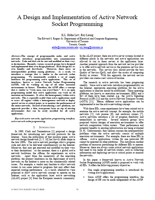
A Design and Implementation of Active NetworkSocket ProgrammingK.L. Eddie Law, Roy LeungThe Edward S. Rogers Sr. Department of Electrical and Computer EngineeringUniversity of TorontoToronto, Canadaeddie@, roy.leung@utoronto.caAbstract—The concept of programmable nodes and active networks introduces programmability into communication networks. Code and data can be sent and modified on their ways to destinations. Recently, various research groups have designed and implemented their own design platforms. Each design has its own benefits and drawbacks. Moreover, there exists an interoperability problem among platforms. As a result, we introduce a concept that is similar to the network socket programming. We intentionally establish a set of simple interfaces for programming active applications. This set of interfaces, known as Active Network Socket Programming (ANSP), will be working on top of all other execution environments in future. Therefore, the ANSP offers a concept that is similar to “write once, run everywhere.” It is an open programming model that active applications can work on all execution environments. It solves the heterogeneity within active networks. This is especially useful when active applications need to access all regions within a heterogeneous network to deploy special service at critical points or to monitor the performance of the entire networks. Instead of introducing a new platform, our approach provides a thin, transparent layer on top of existing environments that can be easily installed for all active applications.Keywords-active networks; application programming interface; active network socket programming;I. I NTRODUCTIONIn 1990, Clark and Tennenhouse [1] proposed a design framework for introducing new network protocols for the Internet. Since the publication of that position paper, active network design framework [2, 3, 10] has slowly taken shape in the late 1990s. The active network paradigm allows program code and data to be delivered simultaneously on the Internet. Moreover, they may get executed and modified on their ways to their destinations. At the moment, there is a global active network backbone, the ABone, for experiments on active networks. Apart from the immaturity of the executing platform, the primary hindrance on the deployment of active networks on the Internet is more on the commercially related issues. For example, a vendor may hesitate to allow network routers to run some unknown programs that may affect their expected routing performance. As a result, alternatives were proposed to allow active network concept to operate on the Internet, such as the application layer active networking (ALAN) project [4] from the European research community. In the ALAN project, there are active server systems located at different places in the networks and active applications are allowed to run in these servers at the application layer. Another potential approach from the network service provider is to offer active network service as the premium service class in the networks. This service class should provide the best Quality of Service (QoS), and allow the access of computing facility in routers. With this approach, the network service providers can create a new source of income.The research in active networks has been progressing steadily. Since active networks introduce programmability on the Internet, appropriate executing platforms for the active applications to execute should be established. These operating platforms are known as execution environments (EEs) and a few of them have been created, e.g., the Active Signaling Protocol (ASP) [12] and the Active Network Transport System (ANTS) [11]. Hence, different active applications can be implemented to test the active networking concept.With these EEs, some experiments have been carried out to examine the active network concept, for example, the mobile networks [5], web proxies [6], and multicast routers [7]. Active networks introduce a lot of program flexibility and extensibility in networks. Several research groups have proposed various designs of execution environments to offer network computation within routers. Their performance and potential benefits to existing infrastructure are being evaluated [8, 9]. Unfortunately, they seldom concern the interoperability problems when the active networks consist of multiple execution environments. For example, there are three EEs in ABone. Active applications written for one particular EE cannot be operated on other platforms. This introduces another problem of resources partitioning for different EEs to operate. Moreover, there are always some critical network applications that need to run under all network routers, such as collecting information and deploying service at critical points to monitor the networks.In this paper, a framework known as Active Network Socket Programming (ANSP) model is proposed to work with all EEs. It offers the following primary objectives.• One single programming interface is introduced for writing active applications.• Since ANSP offers the programming interface, the design of EE can be made independent of the ANSP.This enables a transparency in developing andenhancing future execution environments.• ANSP addresses the interoperability issues among different execution environments.• Through the design of ANSP, the pros and cons of different EEs will be gained. This may help design abetter EE with improved performance in future.The primary objective of the ANSP is to enable all active applications that are written in ANSP can operate in the ABone testbed . While the proposed ANSP framework is essential in unifying the network environments, we believe that the availability of different environments is beneficial in the development of a better execution environment in future. ANSP is not intended to replace all existing environments, but to enable the studies of new network services which are orthogonal to the designs of execution environments. Therefore, ANSP is designed to be a thin and transparent layer on top of all execution environments. Currently, its deployment relies on automatic code loading with the underlying environments. As a result, the deployment of ANSP at a router is optional and does not require any change to the execution environments.II. D ESIGN I SSUES ON ANSPThe ANSP unifies existing programming interfaces among all EEs. Conceptually, the design of ANSP is similar to the middleware design that offers proper translation mechanisms to different EEs. The provisioning of a unified interface is only one part of the whole ANSP platform. There are many other issues that need to be considered. Apart from translating a set of programming interfaces to other executable calls in different EEs, there are other design issues that should be covered, e.g., • a unified thread library handles thread operations regardless of the thread libraries used in the EEs;• a global soft-store allows information sharing among capsules that may execute over different environmentsat a given router;• a unified addressing scheme used across different environments; more importantly, a routing informationexchange mechanism should be designed across EEs toobtain a global view of the unified networks;• a programming model that should be independent to any programming languages in active networks;• and finally, a translation mechanism to hide the heterogeneity of capsule header structures.A. Heterogeneity in programming modelEach execution environment provides various abstractions for its services and resources in the form of program calls. The model consists of a set of well-defined components, each of them has its own programming interfaces. For the abstractions, capsule-based programming model [10] is the most popular design in active networks. It is used in ANTS [11] and ASP [12], and they are being supported in ABone. Although they are developed based on the same capsule model, their respective components and interfaces are different. Therefore, programs written in one EE cannot run in anther EE. The conceptual views of the programming models in ANTS and ASP are shown in Figure 1.There are three distinct components in ANTS: application, capsule, and execution environment. There exist user interfaces for the active applications at only the source and destination routers. Then the users can specify their customized actions to the networks. According to the program function, the applications send one or more capsules to carry out the operations. Both applications and capsules operate on top of an execution environment that exports an interface to its internal programming resources. Capsule executes its program at each router it has visited. When it arrives at its destination, the application at destination may either reply it with another capsule or presents this arrival event to the user. One drawback with ANTS is that it only allows “bootstrap” application.Figure 1. Programming Models in ASP and ANTS.In contrast, ASP does not limit its users to run “bootstrap” applications. Its program interfaces are different from ANTS, but there are also has three components in ASP: application client, environment, and AAContext. The application client can run on active or non-active host. It can start an active application by simply sending a request message to the EE. The client presents information to users and allows its users to trigger actions at a nearby active router. AAContext is the core of the network service and its specification is divided into two parts. One part specifies its actions at its source and destination routers. Its role is similar to that of the application in ANTS, except that it does not provide a direct interface with the user. The other part defines its actions when it runs inside the active networks and it is similar to the functional behaviors of a capsule in ANTS.In order to deal with the heterogeneity of these two models, ANSP needs to introduce a new set of programming interfaces and map its interfaces and execution model to those within the routers’ EEs.B. Unified Thread LibraryEach execution environment must ensure the isolation of instance executions, so they do not affect each other or accessThe authors appreciate the Nortel Institute for Telecommunications (NIT) at the University of Toronto to allow them to access the computing facilitiesothers’ information. There are various ways to enforce the access control. One simple way is to have one virtual machine for one instance of active applications. This relies on the security design in the virtual machines to isolate services. ANTS is one example that is using this method. Nevertheless, the use of multiple virtual machines requires relatively large amount of resources and may be inefficient in some cases. Therefore, certain environments, such as ASP, allow network services to run within a virtual machine but restrict the use of their services to a limited set of libraries in their packages. For instance, ASP provides its thread library to enforce access control. Because of the differences in these types of thread mechanism, ANSP devises a new thread library to allow uniform accesses to different thread mechanisms.C. Soft-StoreSoft-store allows capsule to insert and retrieve information at a router, thus allowing more than one capsules to exchange information within a network. However, problem arises when a network service can execute under different environments within a router. The problem occurs especially when a network service inserts its soft-store information in one environment and retrieves its data at a later time in another environment at the same router. Due to the fact that execution environments are not allowed to exchange information, the network service cannot retrieve its previous data. Therefore, our ANSP framework needs to take into account of this problem and provides soft-store mechanism that allows universal access of its data at each router.D. Global View of a Unified NetworkWhen an active application is written with ANSP, it can execute on different environment seamlessly. The previously smaller and partitioned networks based on different EEs can now be merging into one large active network. It is then necessary to advise the network topology across the networks. However, different execution environments have different addressing schemes and proprietary routing protocols. In order to merge these partitions together, ANSP must provide a new unified addressing scheme. This new scheme should be interpretable by any environments through appropriate translations with the ANSP. Upon defining the new addressing scheme, a new routing protocol should be designed to operate among environments to exchange topology information. This allows each environment in a network to have a complete view of its network topology.E. Language-Independent ModelExecution environment can be programmed in any programming language. One of the most commonly used languages is Java [13] due to its dynamic code loading capability. In fact, both ANTS and ASP are developed in Java. Nevertheless, the active network architecture shown in Figure 2 does not restrict the use of additional environments that are developed in other languages. For instance, the active network daemon, anted, in Abone provides a workspace to execute multiple execution environments within a router. PLAN, for example, is implemented in Ocaml that will be deployable on ABone in future. Although the current active network is designed to deploy multiple environments that can be in any programming languages, there lacks the tool to allow active applications to run seamlessly upon these environments. Hence, one of the issues that ANSP needs to address is to design a programming model that can work with different programming languages. Although our current prototype only considers ANTS and ASP in its design, PLAN will be the next target to address the programming language issue and to improve the design of ANSP.Figure 2. ANSP Framework Model.F. Heterogeneity of Capsule Header StructureThe structures of the capsule headers are different in different EEs. They carries capsule-related information, for example, the capsule types, sources and destinations. This information is important when certain decision needs to be made within its target environment. A unified model should allow its program code to be executed on different environments. However, the capsule header prevents different environments to interpret its information successfully. Therefore, ANSP should carry out appropriate translation to the header information before the target environment receives this capsule.III. ANSP P ROGRAMMING M ODELWe have outlined the design issues encountered with the ANSP. In the following, the design of the programming model in ANSP will be discussed. This proposed framework provides a set of unified programming interfaces that allows active applications to work on all execution environments. The framework is shown in Figure 2. It is composed of two layers integrated within the active network architecture. These two layers can operate independently without the other layer. The upper layer provides a unified programming model to active applications. The lower layer provides appropriate translation procedure to the ANSP applications when it is processed by different environments. This service is necessary because each environment has its own header definition.The ANSP framework provides a set of programming calls which are abstractions of ANSP services and resources. A capsule-based model is used for ANSP, and it is currently extended to map to other capsule-based models used in ANTSand ASP. The mapping possibility to other models remains as our future works. Hence, the mapping technique in ANSP allows any ANSP applications to access the same programming resources in different environments through a single set of interfaces. The mapping has to be done in a consistent and transparent manner. Therefore, the ANSP appears as an execution environment that provides a complete set of functionalities to active applications. While in fact, it is an overlay structure that makes use of the services provided from the underlying environments. In the following, the high-level functional descriptions of the ANSP model are described. Then, the implementations will be discussed. The ANSP programming model is based upon the interactions between four components: application client , application stub , capsule , and active service base.Figure 3. Information Flow with the ANSP.•Application Client : In a typical scenario, an active application requires some means to present information to its users, e.g., the state of the networks. A graphical user interface (GUI) is designed to operate with the application client if the ANSP runs on a non-active host.•Application Stub : When an application starts, it activates the application client to create a new instance of application stub at its near-by active node. There are two responsibilities for the application stub. One of them is to receive users’ instructions from the application client. Another one is to receive incoming capsules from networks and to perform appropriate actions. Typically, there are two types of actions, thatare, to reply or relay in capsules through the networks, or to notify the users regarding the incoming capsule. •Capsule : An active application may contain several capsule types. Each of them carries program code (also referred to as forwarding routine). Since the application defines a protocol to specify the interactions among capsules as well as the application stubs. Every capsule executes its forwarding routine at each router it visits along the path between the source and destination.•Active Service Base : An active service base is designed to export routers’ environments’ services and execute program calls from application stubs and capsules from different EEs. The base is loaded automatically at each router whenever a capsule arrives.The interactions among components within ANSP are shown in Figure 3. The designs of some key components in the ANSP will be discussed in the following subsections. A. Capsule (ANSPCapsule)ANSPXdr decode () ANSPXdr encode () int length ()Boolean execute ()New types of capsule are created by extending the abstract class ANSPCapsule . New extensions are required to define their own forwarding routines as well as their serialization procedures. These methods are indicated below:The execution of a capsule in ANSP is listed below. It is similar to the process in ANTS.1. A capsule is in serial binary representation before it issent to the network. When an active router receives a byte sequence, it invokes decode() to convert the sequence into a capsule. 2. The router invokes the forwarding routine of thecapsule, execute(). 3. When the capsule has finished its job and forwardsitself to its next hop by calling send(), this call implicitly invokes encode() to convert the capsule into a new serial byte representation. length() isused inside the call of encode() to determine the length of the resulting byte sequence. ANSP provides a XDR library called ANSPXdr to ease the jobs of encoding and decoding.B. Active Service Base (ANSPBase)In an active node, the Active Service Base provides a unified interface to export the available resources in EEs for the rest of the ANSP components. The services may include thread management, node query, and soft-store operation, as shown in Table 1.TABLE I. ACTIVE SERVICE BASE FUNCTION CALLSFunction Definition Descriptionboolean send (Capsule, Address) Transmit a capsule towards its destination using the routing table of theunderlying environment.ANSPAddress getLocalHost () Return address of the local host as an ANSPAddress structure. This isuseful when a capsule wants to check its current location.boolean isLocal (ANSPAddress) Return true if its input argument matches the local host’s address andreturn false otherwise.createThread () Create a new thread that is a class ofANSPThreadInterface (discussed later in Section VIA “Unified Thread Abstraction”).putSStore (key, Object) Object getSStore (key) removeSStore (key)The soft-store operations are provided by putSStore(), getSSTore(), and removeSStore(), and they put, retrieve, and remove data respectively. forName (PathName) Supported in ANSP to retrieve a classobject corresponding to the given path name in its argument. This code retrieval may rely on the code loading mechanism in the environment whennecessary.C. Application Client (ANSPClient)boolean start (args[])boolean start (args[],runningEEs) boolean start (args[],startClient)boolean start (args[],startClient, runningEE)Application Client is an interface between users and the nearby active source router. It does the following responsibilities.1. Code registration: It may be necessary to specify thelocation and name of the application code in some execution environments, e.g., ANTS. 2. Application initialization: It includes selecting anexecution environment to execute the application among those are available at the source router. Each active application can create an application client instance by extending the abstract class, ANSPClient . The extension inherits a method, start(), to automatically handle both the registration and initialization processes. All overloaded versions of start() accept a list of arguments, args , that are passed to the application stub during its initialization. An optional argument called runningEEs allows an application client to select a particular set of environment variables, specified by a list of standardized numerical environment ID, the ANEP ID, to perform code registration. If this argument is not specified, the default setting can only include ANTS and ASP. D. Application Stub (ANSPApplication)receive (ANSPCapsule)Application stubs reside at the source and destination routers to initialize the ANSP application after the application clients complete the initialization and registration processes. It is responsible for receiving and serving capsules from the networks as well as actions requested from the clients. A new instance is created by extending the application client abstract class, ANSPApplication . This extension includes the definition of a handling routine called receive(), which is invoked when a stub receives a new capsule.IV. ANSP E XAMPLE : T RACE -R OUTEA testbed has been created to verify the design correctnessof ANSP in heterogeneous environments. There are three types of router setting on this testbed:1. Router that contains ANTS and a ANSP daemonrunning on behalf of ASP; 2. Router that contains ASP and a ANSP daemon thatruns on behalf of ANTS; 3. Router that contains both ASP and ANTS.The prototype is written in Java [11] with a traceroute testing program. The program records the execution environments of all intermediate routers that it has visited between the source and destination. It also measures the RTT between them. Figure 4 shows the GUI from the application client, and it finds three execution environments along the path: ASP, ANTS, and ASP. The execution sequence of the traceroute program is shown in Figure 5.Figure 4. The GUI for the TRACEROUTE Program.The TraceCapsule program code is created byextending the ANSPCapsule abstract class. When execute() starts, it checks the Boolean value of returning to determine if it is returning from the destination. It is set to true if TraceCapsule is traveling back to the source router; otherwise it is false . When traveling towards the destination, TraceCapsule keeps track of the environments and addresses of the routers it has visited in two arrays, path and trace , respectively. When it arrives at a new router, it calls addHop() to append the router address and its environment to these two arrays. When it finally arrives at the destination, it sets returning to false and forwards itself back to the source by calling send().When it returns to source, it invokes deliverToApp() to deliver itself to the application stub that has been running at the source. TraceCapsule carries information in its data field through the networks by executing encode() and decode(), which encapsulates and de-capsulates its data using External Data Representation (XDR) respectively. The syntax of ANSP XDR follows the syntax of XDR library from ANTS. length() in TraceCapsule returns the data length, or it can be calculated by using the primitive types in the XDRlibrary.Figure 5. Flow of the TRACEROUTE Capsules.V. C ONCLUSIONSIn this paper, we present a new unified layered architecture for active networks. The new model is known as Active Network Socket Programming (ANSP). It allows each active application to be written once and run on multiple environments in active networks. Our experiments successfully verify the design of ANSP architecture, and it has been successfully deployed to work harmoniously with ANTS and ASP without making any changes to their architectures. In fact, the unified programming interface layer is light-weighted and can be dynamically deployable upon request.R EFERENCES[1] D.D. Clark, D.L. Tennenhouse, “Architectural Considerations for a NewGeneration of Protocols,” in Proc. ACM Sigcomm’90, pp.200-208, 1990. [2] D. Tennenhouse, J. M. Smith, W. D. Sicoskie, D. J. Wetherall, and G. J.Minden, “A survey of active network research,” IEEE Communications Magazine , pp. 80-86, Jan 1997.[3] D. Wetherall, U. Legedza, and J. Guttag, “Introducing new internetservices: Why and how,” IEEE Network Magazine, July/August 1998. [4] M. Fry, A. Ghosh, “Application Layer Active Networking,” in ComputerNetworks , Vol.31, No.7, pp.655-667, 1999.[5] K. W. Chin, “An Investigation into The Application of Active Networksto Mobile Computing Environments”, Curtin University of Technology, March 2000.[6] S. Bhattacharjee, K. L. Calvert, and E. W. Zegura, “Self OrganizingWide-Area Network Caches”, Proc. IEEE INFOCOM ’98, San Francisco, CA, 29 March-2 April 1998.[7] L. H. Leman, S. J. Garland, and D. L. Tennenhouse, “Active ReliableMulticast”, Proc. IEEE INFOCOM ’98, San Francisco, CA, 29 March-2 April 1998.[8] D. Descasper, G. Parulkar, B. Plattner, “A Scalable, High PerformanceActive Network Node”, In IEEE Network, January/February 1999.[9] E. L. Nygren, S. J. Garland, and M. F. Kaashoek, “PAN: a high-performance active network node supporting multiple mobile code system”, In the Proceedings of the 2nd IEEE Conference on Open Architectures and Network Programming (OpenArch ’99), March 1999. [10] D. L. Tennenhouse, and D. J. Wetherall. “Towards an Active NetworkArchitecture”, In Proceeding of Multimedia Computing and Networking , January 1996.[11] D. J. Wetherall, J. V. Guttag, D. L. Tennenhouse, “ANTS: A toolkit forBuilding and Dynamically Deploying Network Protocols”, Open Architectures and Network Programming, 1998 IEEE , 1998 , Page(s): 117 –129.[12] B. Braden, A. Cerpa, T. Faber, B. Lindell, G. Phillips, and J. Kann.“Introduction to the ASP Execution Environment”: /active-signal/ARP/index.html .[13] “The java language: A white paper,” Tech. Rep., Sun Microsystems,1998.。
毕业设计外文翻译

外文文献原稿和译文原稿IntroductionIn the modern industrial control field,along with the rapid developmentof computer technology,the emergence of a new trend o fintelligent control, namely to machinesimulationhuman thinkingmode, using reasoning, deduce and induction,so the means, the production control, thisisartificialintelligence.One expertsystem,fuzzy logicand neuralnetwork is the artificial intelligence of several keyresearch hot spot. Relativeto the expert system,the fuzzy logicbelongs to the category of c omputational mathematicsandcontainthe genetic algorithm,the chaos theoryandlinear theoryetc,it comprehensive of operators practice experience,has thedesign issimple andeasy to use, strong anti-interference abilityand reaction speed,ea sy tocontrol and adaptiveability, etc. In recent years, ina process control,built to touch, estimation, identify,diagnosis, the stockmarket forecast,agriculturalproductionandmilitary sciences toawiderange ofapplications.To carry o ut in-depthresearch and application offuzzy control technology, the paperintroduces thebasic theory offuzzycontrol technology and development,andto some in the application ofthepower electronics areintroduced.Fuzzy Logic andFuzzyControl1,fuzzy logic and fuzzy controlconceptIn1965,the university of California, Berkeley, computer expertsLoftyZadeh put forward"fuzzylogic" concept,the root lies inthearea'slogic orclear logic distribution, usedto define theconfused,unable to quantify orthe problem ofp recision,for ˙ in a man'svonbased on"true-false" reasoningmechanism, and thus createa electronic circuit and integrated circuit of theBoolean algorithm, fuzzy logic to fill thegapsin specialthings insampling and analysis ofblank.On the basisof fuzzy logic fuzzy set theory, aparticular things as the set of features membership, he can be in"is" and"no" within the scop eofthe takebetween any value. And fuzzy logicis reasonablequantitativemathematicaltheory,the mathematical basis forfundamental for isto deal with thesethe statistical uncertai nimprecise information.Fuzzy control based onfuzzylogic isa processo fdescription of the control algorithm.For parameters preciselyknownmathematical model, wecan use Berd grap hor chart toanalyststhe Nyquist process to obtain th eaccuratedesign parameters.Andfor some complex system, such as particle reaction, meteorological forecast equipment, establishing a reasonable and accurate mathematicalmodel is very difficult,and for power transmissionspeedof vectorcontrol problems,although it can be measured byt he modelthat,butfor many variables andnonlinearvariation, the accuratecontrol is very difficult. And fuzzy control technology only on the basis ofthepractical experience and the operator andintuitive inference,also relies ondesign personnel an dresearch and developmentpersonnel of experience and knowledge accumulation,itdoes not needto establish equipment model,so basically is adaptive,and havestrong robustnes s.After manyyears development, therehave been manysuccessful application ofthefuzzy control theory of the case, s uch asRutherford, Carter and Ostergaardwere applied and metallurgical furnaceand heat exchangerscontroldevic e.2,the analysis method is discussedIndustrial control stabilityof the systemisdiscussedthe premise of the problem, because of the nonlinear and not to the unity of the description,make a judgment,sothefuzzy co ntrolsystem analysis method ofstability analysis has beena hot spot,comprehensive in recentyears youof scholars paper published thesystem stability analysis has these several circumstances :1), LiPuYa panov method: direct method based on the discrete t ime (D-T)and continuous time fuzzy control stabilityanalysis and designmethod, the stability condition of the relative comparis onconservative.2), sliding variablestructuresystem analysis method3),round stability criterionmethods: use sector bounded nonlinearconcept, according to the stability criterion, led to the stability of thefuzzycontrol.4),POPOVcriterion5), othermethodssuch asrelationship matrix analys is, exceed stable theory, phase-plane, matrix inequality or conve xoptimization method,fuzzyhole-hole mapping etc, detailed information and relevantliterature many, in this one no longer etc.Set Design ofFuzzy ControlThe design of the fuzzy control is a very complicated process,in general, take thedesign steps and tools is more normative.Thefuzzycontroller generaluse of the special software andhardwa re,universalhardwarechip in on the marketat present ismore, includingmain products are shownbelow. And special IC has developedveryfast,itspecial IC and softwarecont roller integratesin together.In the processof design,thedesignof thegeneral to take stepsfor:1,consideringwhether the subject by fuzzycontrol system.That is considered the routine controlmode ofmay.2, from equipment operation personnel place togetas much information.3 and selecting the mathematical model could, if use the conventionalmethod design,estimate the equipment performance characteristics.4, determinethe fuzzy logiccontrolobject.5, determine the inputand output variables.6,determine thevariables asdetermined the belonging of the range.7, confirmthe variables of the corresponding rules.8, determinethe scale coefficients.9,ifhaveaready-made, mathematical model of fuzzycontroller with already certainof system simulation, observation equipment performance,and constantly adjustrules and scale coefficientsuntilreachingsatisfaction performance. Or to design fuzzy controller.10,real-timeoperation controller, constantly adjust to the best performance.FuzzyControlApplication and ProspectAs artificial intelligence of anewresearch field, thefuzzycontrol absorb lessons from the traditional design method and other newtechnology's essence,in manyfields has madeconsiderableprogress. In the new typeof powerelectronic andautomatic controlsystem,some expertsin the linearadding theconditions ofthe poweramplifier, the application of thefuzzy control based on the servo motor control,in the fuzzycontrol syst em withthe PIDand model referenceadaptive control(MRAC)comparison proved the advantages of the method of fuzzycontrol. Fuzzy turn sentgain tuned controller viewsofthe induction motor drive system vector controlFuzzycontrol as a is the development of new technology, now inmost experts also to focus onapplicationsystemresearch, and make considerable achievement, butin the theory resea rch and system analysisor relative backward, somuch so that some scholars have questionedits theoretical basis andeffective. In view ofthiscanbe clear that the fuzzy control thecombinationof theory and practice isstillneedstobe further explored. Thedevelopment prospects are veryattractive, andin recent years,its theoreticalstudy also madesignificant progress.In thepast forty years of thedevelopment process, the f uzzycontrol alsohas somelimitations: 1) control precisionlo w,performance is not high,stability is poorer;2)theory system is not complete. 3) theadaptive ability low.Fortheseweaknesses,the fuzzy control and someothernew technology, suchas neuralnetwork(NN), genetic algorithm,and t he combination of to a higherlevel ofapplicationdevelopmentexpand the huge space.SummaryFuzzy control as a comprehensiveapplication example, in the globalinformationthe push ofwave, in the nextfewd ecades, to the rapiddevelopment of economy will injectne wvitality,the expert thinks,thenext generation ofindust rial control isthe basis of fuzzy control and neural network, and chaos theory as the pillar oftheartificial intelligence.Wi ththe fuzzycontroltheory research and further more perfect of, the scope ofapplicationofthe growingand supportingthe development and manufactureofIC,thefuzzycontrolwill be open tothe field of industrial automation development oflightapplicationprospect, but also tothevarious areas of the researchers suggestmore important task.译文引言在现代工业控制领域,伴随着计算机技术的突飞猛进,出现了智能控制的新趋势,即以机器模拟人类思维模式,采用推理、演绎和归纳等手段,进行生产控制,这就是人工智能。
毕业设计外文文献翻译
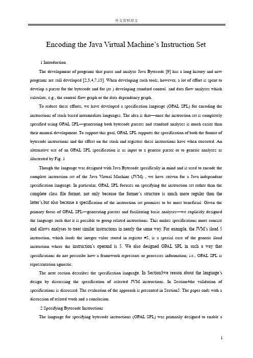
Encoding the Java Virtual Machine’s Instruction Set1 IntroductionThe development of programs that parse and analyze Java Bytecode [9] has a long history and new programs are still developed [2,3,4,7,13]. When developing such tools, however, a lot of effort is spent to develop a parser for the bytecode and for (re-) developing standard control- and data-flow analyses which calculate, e.g., the control-flow graph or the data-dependency graph.To reduce these efforts, we have developed a specification language (OPAL SPL) for encoding the instructions of stack-based intermediate languages. The idea is that—once the instruction set is completely specified using OPAL SPL—generating both bytecode parsers and standard analyses is much easier than their manual development. To support this goal, OPAL SPL supports the specification of both the format of bytecode instructions and the effect on the stack and registers these instructions have when executed. An alternative use of an OPAL SPL specification is as input to a generic parser or to generic analyses as illustrated by Fig. 1Though the language was designed with Java Bytecode specifically in mind and is used to encode the complete instruction set of the Java Virtual Machine (JVM) , we have striven for a Java-independent specification language. In particular, OPAL SPL focuses on specifying the instruction set rather than the complete class file format, not only because the former’s structure is much more regular than the latter’s,but also because a specifi cation of the instruction set promises to be most beneficial. Given the primary focus of OPAL SPL—generating parsers and facilitating basic analyses—we explicitly designed the language such that it is possible to group related instructions. This makes specifications more concise and allows analyses to treat similar instructions in nearly the same way. For example, the JVM’s iload 5 instruction, which loads the integer value stored in register #5, is a special case of the generic iload instruction where the instruction’s operand is 5. We also designed OPAL SPL in such a way that specifications do not prescribe how a framework represents or processes information; i.e., OPAL SPL is representation agnostic.The next section describes the specification langua ge. In Section3we reason about the language’s design by discussing the specification of selected JVM instructions. In Section4the validation of specifications is discussed. The evaluation of the approach is presented in Section5. The paper ends with a discussion of related work and a conclusion.2 Specifying Bytecode InstructionsThe language for specifying bytecode instructions (OPAL SPL) was primarily designed to enable aconcise specification of the JVM’s instruction set. OPAL SPL supports the sp ecification of both an instruction’s format and its effect on the stack and local variables (registers)when the instruction is executed. It is thus possible to specify which kind of values are popped from and pushed onto the stack as well as which local variables are read or written. Given a specification of the complete instruction set the information required by standard control- and data-flow analyses is then available.However, OPAL SPL is not particularly tied to Java as it abstracts from the particularities of the JVM Specification. For example, the JVM’s type system is part of an OPAL SPL specification rather than an integral part of the OPAL SPL language itself.Next, we first give an overview of the language before we discuss its semantics.2.1 SyntaxThe OPAL Specification Language (OPAL SPL) is an XML-based language. Its grammar is depicted in Fig.2using an EBNF-like format. Non-terminals are written in capital letters (INSTRUCTIONS, TYPES, etc.), the names of XML-elements are written in small letters (types, stack, etc.) and the names of XML-attributes start with ―@‖ (@type, @var, etc.). We refer to the content of an XML-element using symbols that start with―/‖ (/V ALUEEXPRESSION, /EXPECTEDV ALUE, etc.). ―<>‖ is used to specify nesting of elements. ―( ),?,+,*,{},|‖ have the usual semantics. For example,exceptions<(exception @type)+>specifies that the XML-elementexceptionshas one or moreexceptionchild elements that always have the attributetype.2.2 SemanticsFormat SpecificationEach specification written in OPAL SPL consists of four major parts (line 1 in Fig.2). The first part(types, lines 2–3) specifies the type system that is used by the underlying virtual machine. The second part (exceptions, line 4) declares the exceptions that may be thrown when instructions are executed. The third part (functions, line 5) declares the functions that are used in instruction specifications. The fourth part is the specification of the instructions themselves (lines 6–12), each of which may resort to the declared functions to access information not simply stored along with the instruction. For example,invoke instructions do not store the signature and declaring class of the called methods. Instead, a reference to an entry in the so-called constant pool is stored. Only this constant pool entry has all information about the method. To obtain, e.g., the return type of the called method, an abstract function TYPE method refreturn type(method ref) is declared that takes a reference to the entry as i nput and returns the method’s return type. Using abstract function declarations, we abstract—in the specification of the instructions—from the concrete representation of such information by the enclosing by tecode toolkit.The specification of an instruction consists of up to four parts:the instruction’s format (lines 7–8), a description of the effect the instruction has on the stack when executed (lines 9–10), a descriptions of theregisters it affects upon execution (lines 11–12), and information about the exceptions that may be thrown during execution (end of line 6). An instruction’s format is specified by sequences which describe how an instruction is stored. Theu1, u2andu4elements (line 8) of each format sequence specify that the current value is an unsigned integer value with 1, 2 and 4 bytes, respectively. Similarly, thei1, i2 andi4 elements (line 8) are used to specify that the current value is a (1, 2 or 4 byte) signed integer value. The values can be bound to variables using thevarat tribute and can be given a second semantics using thetype attribute. For example,<i2 type=‖short‖ var=‖value‖/>is a twobyte signed integer value that is bound to the variable value and has type short with respect to the instruction set’s type system. Additionally, it is possible to specify expected values (line 8). This enables the selection of the format sequence to be used for reading in the instruction. E.g., <sequence><u1 var=‖opcode‖>171</u1>... specifies that this sequence matches if the value of the first byt e is 171. A sequence’s list element is used to specify that a variable number of values need to be read. The concrete number of elements is determined by the count attribute. The attribute’s value is an expression that can use values that were previously assigned to a variable. The sequence elements implicit and implicit type are used to bind implicit value and type information to variables that can later on be used in type or value expressions(line 7, 10 and 11). To make it possible to aggregate related bytecode instructions to one logical instruction, several format sequences can be defined. The effect on the stack is determined by the number and type of stack operands that are popped (line 9) and pushed (line 10). If multiple stack layouts are specified, the effect on the stack is determined by the firstbefore-executionstack layout that matches; i.e., to determine the effect on the stack a data-flow analysis is necessary.Unique Prefix RuleOne constraint placed upon specifications written in OPAL SPL is that a format sequence can be identified unambiguously by only parsing a prefix of the instruction; no lookahead is necessary. In other words, if each format sequence is considered a production and eachu1, u2, etc. is considered a terminal, then OPAL SPL requires the format sequences to constitute an LR(0) grammar This unique prefix rule is checked automatically (cf. Sec.4); furthermore, this rule facilitates generating fast parsers from the specification, e.g., using nestedswitchstatements.Type SystemOPAL SPL does not have a hard-coded type hierarchy. Instead, each specification written in SPL contains a description of the type system used by the bytecode language being described. The only restriction is that all types have to be arranged in a single, strict hierarchy.The Java Virtual Machine Specification [9]’s type hierarchy is shown in Fig.3(1). It captures all runtime types known to the Java virtual machine, as well as those types that are used only at link- or compile-time, e.g., branchoffset, fieldref and methodref. The hierarchy is a result of the peculiarities of theJVM’s instruction set. The byteorbooleantype, e.g., is required to model the baloadandbastore instructions, which operate on arrays of byteorbooleanalike.OPAL SPL’s type system implicitly defines a second type hierarchy ((2) in Fig. 3). The declared hierarchy of types (1) is mirrored by a hierarchy of kinds (2); for every (lower-case) type there automatically exists an (upper-case) kind. This convention ensures their consistency and keeps the specification itself brief. The values of kindINT LIKEareint, short, etc., just as the values of type int like are 1, 2, etc. Kinds enable parameterizing logical instructions likeareturnwith types,thus making a concise specification of related instructions (e.g., freturn, ireturn, andareturn) possible (cf. Sec.3.12).Information FlowIn OPAL SPL, the flow of information (values, types, register IDs) is modeled by means of named variables and expressions using the variables. In general, the flow of information is subject to the constraints illustrated by Fig.4. For example, variables defined within a specific format sequence can only be referred to by later elements within the same format sequence; a variable cannot be referred to across format sequences. If the same variable is bound by all format sequences, i.e., it is common to all format sequences, then the variable can be used to identify register IDs, the values pushed onto the stack, etc. Similarly, if an instruction defines multiple stack layouts, then a value can only flow from the i-th stack layout before execution to the i-th stack layout after execution and only information that is common to all stack layouts before execution may be stored in a register.3 Design DiscussionThe design of the OPAL specification language (OPAL SPL) is influenced by the peculiarities of the JVM’s instruction set [9, Chapter 6]. In the following, we discuss those instructions that had a major influence on the design.3.1 Modeling the Stack Bottom(athrow)All JVM instructions—with the exception ofathrow—specify only the number and types of operands popped from and pushed onto the stack; they do not determine the layout of the complete stack. In case of the athrowinstruction, however, the stack layout after its execution is completely determined (Fig.5, line 6); the single element on the stack is the thrown exception. This necessitates explicit modeling of the stack’s contents beyond the operands that are pushed and popped by a particular instruction. The explicit modeling of the rest of the stack (line5) here by allows for the (implicit) modeling of stacks of a fixed size (line6).3.2 Pure Register Instructions(iinc)The flow of information for instructions that do not affect the stack—e.g., the JVM’siinc instruction—is depicted in Fig. 7and adheres to the general scheme of information flow (cf. Fig. 4). After parsing the instruction according to the format sequence(Fig. 6, lines3–5), the two variables lvIndex an dincrement are initialized.3.3 Interpretation of Arithmetic Instructions (iinc, add, sub,etc.)The specification ofiinc (Fig. 6) also illustrates OPAL SPL’s ability to model computed values, e.g., add(value, increment). This information can subsequently be used, e.g., by static analyses to determine data dependencies or to perform abstract interpretations.3.4 Constant Pool Handling (ldc)The Java class file format achieves its compactness in part through the use of a constant pool. Hereby, immediate operands of an instruction are replaced by an index into the (global) pool. For example, in case of the load constant intructionldc, the operand needs to be programmatically retrieved from the constant pool (Fig.8, line 5). To obtain the value’s type, one uses the reflective type offunction that the enclosing toolkitx has to provide (line14).3.5 Multiple Format Sequences, Single Logical InstructionAn instruction such asldc, which may refer to an integer value in the constant pool, is conceptually similar to instructions such asiconst 0orsipush;allofthem push a constant value onto the operand stack. The primary difference between the format sequences of ldc(Fig. 8, lines 3–5)andiconst 0(lines 6–7)isthat the former’s operand resides in th e constant pool. In contrast, sipushencodes its operand explicitly in the bytecode stream as an immediate value (line9).To facilitate standard control- and data-flow analyses, OPAL SPL abstracts away from such details, so that similar instructions can be subsumed by more generic instructions using explicit or implicit type and value bindings. A generic push instruction (Fig. 8), e.g., subsumes all JVM instructions that just push a constant value onto the stack. In this case the pushed value is either a computed value (line5), an implicit value (line7), or an immediate operand (line9).3.6 Variable Operand Counts (invokevirtual, invokespecial,etc.)Some instructions pop a variable number of operands, e.g., the four invoke instructions invokevirtual, invokespecial, invokeinterface,andinvokestatic. In their case the number of popped operands directly depends on the number of arguments of the method. To support instructions that pop a variable number of operands, OPAL SPL provides the list element (Fig.9, line 8). Using the list element’scountattribute, it is possible to specify a function that determines the number of operands actually popped from the stack. It is furthermore possible, by using theloop varattribute, to specify a variable iterating over these operands. The loop variable (i) can then be used inside the list element to specify the expected operands (line10). This enables specification of both the expected number and type of operands, i.e., of the method arguments (lines8–10).Using functions (methodrefargcount, methodrefargtype, ...) offloads the intricate handling of the constant pool to externally supplied code (cf. Sec.3.4)—the enclosing toolkit; the OPAL specification language itself remains independent of how the framework or toolkit under development stores suchinformation.3.7 ExceptionsThe specification of invokevirtual (Fig. 9) also makes explicit which exceptions the instruction may throw (line 16). This information is required by control-flow analyses and thus needs to be present in specifications. To identify the instructions which may handle the exception the function (caughtby)needs to be defined by the toolkit. This functions computes, given both the instruction’s address and the type of the exception, the addresses of all instructions in the same method that handle the exception. Similar to the handling of the constant pool, OPAL SPL thus offloads the handling of the exceptions attribute.3.8 Variable-length Instructions (tableswitch, lookupswitch)The support for variable-length instructions (tableswitch, lookupswitch) is similar to the support for instructions with a variable stack size (cf. Sec. 3.6). In this case, anelementselement can be used to specify how many times (Fig.10, line 7) which kind of values (lines8–9) need to be read. Hereby, the elementsconstruct can accommodate multiple sequence elements (lines7–10).The variable number of cases is, however, just one reason why table switch and lookupswitch are classified as variable-length instructions; the JVM Specification mandates that up to three padding bytes are inserted, to align the following format elements on a four-byte boundary (line4).3.9 Single Instruction, Multiple Operand Stacks (dup2)The JVM specification defines several instructions that operate on the stack independent of their operands’ types or—if we change the perspective—that behave differently depending on the type of the operands present on the stack prior to their execution. For example, thedup2instruction (Fig. 11) duplicates the contents of two one-word stack slots.Instructions such asdup2anddup2x1distinguish their operands by their computational type (category 1 or 2) rather than by their actual type (int, reference,etc.). This makes it possible to compactly encode instructions such asdup2and motivates the corresponding level in the type hierarchy (cf. Sec.2.2). Additionally, this requires that OPAL SPL supports multiple stack layouts.In OPAL SPL, the stack is modeled as a list of operands, not as a list of slots as discussed in the JVM specification. While the effect of an instruction such asdup2 is more easily expressed in terms of stack slots, the vast majority of instructions naturally refers to operands. In particular, the decision to base the stack model on operands rather than slots avoids explicit modeling of the higher and lower halves of category-2-values, e.g., the high and low word of a 64 bitlong operand.3.10 (Conditional) Control Transfer Instructions (if, goto, jsr, ret)To perform control-flow analyses it is necessary to identify those instructions that may transfer control, either by directly manipulating the program counter or terminating the current method. This information is specified using theinstruction element’s optional transferscontrol attribute (Fig.12, line 1). Itspecifies if control is transfered conditionally or always. The target instruction to which control is transferredisidentifiedbythevaluesoftype branchoffset orabsoluteaddress.For these two types the type system contains the meta-information (cf. Fig.3)thatthe values have to be interpreted either as relative or absolute program counters.3.11 Multibyte Opcodes and Modifiers (wideinstructions, newarray)The JVM instruction set consists mostly of instructions whose opcode is a single byte, although a few instructions have longer opcode sequences. In most cases this is due to the widemodifier, a single byte prefix to the instruction. In case of the newarray instruction, however, a suffix is used to determine its precise effect. As can be seen in Fig.13, the parser needs to examine two bytes to determine the correct format sequence.3.12 Implicit Types and Type ConstructorsThe specification ofnewarray(Fig.13) also illustrates the specification of implied types and type constructors. As the JVM instruction set is a typed assembly language, many instructions exist in a variety of formats, e.g., asiadd, ladd, fadd, anddadd.Theimplicit type construct is designed to eliminate this kind of redundancy in the specification, resulting in a single, logical instruction:add. Similarily, newarraymakes use of type bindings (lines5, 8).But, to precisely model the effect ofnewarrayon the operand stack, an additional function that constructs a type is needed. Given a type and an integer, the function arrayconstructs a new type; here, a one-dimensional array of the base type (line14).3.13 Extension MechanismOPAL SPL has been designed with extensibility in mind. The extension point for additional information is the instruction element’sappinfochild, whose content can consist of arbitrary elements with a namespace other than OPAL SPL’s own.To illustrate the mechanism, suppose that we want to create a Prolog representation for Java Bytecode, in which information about operators is explicit, i.e., in which theifgt instruction is an if instruction which compares two values using the greater than operator, as illustrated by Fig.14.4 V alidating SpecificationsTo validate an OPAL SPL specification, we have defined an XML Schema which ensures syntactic correctness of the specification and performs basic identity checking. It checks, for example, that each declared type and each instruction’s mnemonic is unique. Additionally, we have developed a program which analyzes a specification and detects the following errors: (a) a format sequence does not have a unique prefix path, (b) multiple format sequences of a single instruction do not agree in the variables bound by them, (c) the number or type of function’s a rguments is wrong or its result is of the wrong type.5 EvaluationWe have used the specification of the JVM’s instruction set [9] for the implementation of a highly flexible bytecode toolkit. The toolkit supports four representations of Java bytecode: a native representation, which is a one-to-one representation of the Java Bytecode; a higher-level representation, which abstracts away some details of Java bytecode—in particular from the constant pool; an XML representation which uses the higher-level representation; a Prolog-based representation of Java Bytecode, which is also based on the higher-level representation.6 Related WorkApplying XML technologies to Java bytecode is not a new idea [5]. The XML serialization of class files, e.g., allows for their declarative transformation using XSLT. The XMLVM [11] project aims to support not only the JVM instruction set [9], but also the CLR instruction set [8]. This requires that at least the CLR’s operand stack is transformed [12], as the JVM r equires. The description of the effect that individual CLR instructions have on the operand stack is, however, not specified in an easily accessible format like OPAL SPL, but rather embedded within the XSL transformations.7 Conclusion and Future WorkIn future work, we will investigate the use of OPAL SPL for the encoding of other bytecode languages, such as the Common Intermediate Language. This would make it possible to develop (control- and dataflow-) analyses with respect to the OPAL SPL and to use the same analysis to analyze bytecode of different languages.From:Encoding the Java Virtual Machine’s Instruction SetJava虚拟机指令系统的编码1引言解释和分析Java字节码程序的发展有已经长的历史了,新的方案仍在研究。
毕设三项文档之-外文翻译

本科生毕业设计 (论文)
外文翻译
原文标题
Worlds Collide:
Exploring the Use of Social Media Technologies for
Online Learning
译文标题
世界的碰撞:
探索社交媒体技术在在线学习的应用
作者所在系别计算机科学与工程系作者所在专业计算机科学与技术作者所在班级
作者姓名
作者学号
指导教师姓名
指导教师职称讲师
完成时间2013年2月
北华航天工业学院教务处制
注:1. 指导教师对译文进行评阅时应注意以下几个方面:①翻译的外文文献与毕业设计(论文)的主题是否高度相关,并作为外文参考文献列入毕业设计(论文)的参考文献;②翻译的外文文献字数是否达到规定数量(3 000字以上);③译文语言是否准确、通顺、具有参考价值。
2. 外文原文应以附件的方式置于译文之后。
毕业设计论文外文文献翻译

毕业设计(论文)外文文献翻译院系:财务与会计学院年级专业:201*级财务管理姓名:学号:132148***附件: 财务风险管理【Abstract】Although financial risk has increased significantly in recent years risk and risk management are not contemporary issues。
The result of increasingly global markets is that risk may originate with events thousands of miles away that have nothing to do with the domestic market。
Information is available instantaneously which means that change and subsequent market reactions occur very quickly。
The economic climate and markets can be affected very quickly by changes in exchange rates interest rates and commodity prices。
Counterparties can rapidly become problematic。
As a result it is important to ensure financial risks are identified and managed appropriately. Preparation is a key component of risk management。
【Key Words】Financial risk,Risk management,YieldsI. Financial risks arising1.1What Is Risk1.1.1The concept of riskRisk provides the basis for opportunity. The terms risk and exposure have subtle differences in their meaning. Risk refers to the probability of loss while exposure is the possibility of loss although they are often used interchangeably。
毕设外文文献+翻译1

毕设外文文献+翻译1外文翻译外文原文CHANGING ROLES OF THE CLIENTS、ARCHITECTSAND CONTRACTORS THROUGH BIMAbstract:Purpose –This paper aims to present a general review of the practical implications of building information modelling (BIM) based on literature and case studies. It seeks to address the necessity for applying BIM and re-organising the processes and roles in hospital building projects. This type of project is complex due to complicated functional and technical requirements, decision making involving a large number of stakeholders, and long-term development processes.Design/methodology/approach–Through desk research and referring to the ongoing European research project InPro, the framework for integrated collaboration and the use of BIM are analysed.Findings –One of the main findings is the identification of the main factors for a successful collaboration using BIM, which can be recognised as “POWER”: product information sharing (P),organisational roles synergy (O), work processes coordination (W), environment for teamwork (E), and reference data consolidation (R).Originality/value –This paper contributes to the actual discussion in science and practice on the changing roles and processes that are required to develop and operate sustainable buildings with the support of integrated ICT frameworks and tools. It presents the state-of-the-art of European research projects and some of the first real cases of BIM application inhospital building projects.Keywords:Europe, Hospitals, The Netherlands, Construction works, Response flexibility, Project planningPaper type :General review1. IntroductionHospital building projects, are of key importance, and involve significant investment, and usually take a long-term development period. Hospital building projects are also very complex due to the complicated requirements regarding hygiene, safety, special equipments, and handling of a large amount of data. The building process is very dynamic and comprises iterative phases and intermediate changes. Many actors with shifting agendas, roles and responsibilities are actively involved, such as: the healthcare institutions, national and local governments, project developers, financial institutions, architects, contractors, advisors, facility managers, and equipment manufacturers and suppliers. Such building projects are very much influenced, by the healthcare policy, which changes rapidly in response to the medical, societal and technological developments, and varies greatly between countries (World Health Organization, 2000). In The Netherlands, for example, the way a building project in the healthcare sector is organised is undergoing a major reform due to a fundamental change in the Dutch health policy that was introduced in 2008.The rapidly changing context posts a need for a building with flexibility over its lifecycle. In order to incorporate life-cycle considerations in the building design, construction technique, and facility management strategy, a multidisciplinary collaboration is required. Despite the attempt for establishing integrated collaboration, healthcare building projects still facesserious problems in practice, such as: budget overrun, delay, and sub-optimal quality in terms of flexibility, end-user?s dissatisfaction, and energy inefficiency. It is evident that the lack of communication and coordination between the actors involved in the different phases of a building project is among the most important reasons behind these problems. The communication between different stakeholders becomes critical, as each stakeholder possesses different setof skills. As a result, the processes for extraction, interpretation, and communication of complex design information from drawings and documents are often time-consuming and difficult. Advanced visualisation technologies, like 4D planning have tremendous potential to increase the communication efficiency and interpretation ability of the project team members. However, their use as an effective communication tool is still limited and not fully explored. There are also other barriers in the information transfer and integration, for instance: many existing ICT systems do not support the openness of the data and structure that is prerequisite for an effective collaboration between different building actors or disciplines.Building information modelling (BIM) offers an integrated solution to the previously mentioned problems. Therefore, BIM is increasingly used as an ICT support in complex building projects. An effective multidisciplinary collaboration supported by an optimal use of BIM require changing roles of the clients, architects, and contractors; new contractual relationships; and re-organised collaborative processes. Unfortunately, there are still gaps in the practical knowledge on how to manage the building actors to collaborate effectively in their changing roles, and todevelop and utilise BIM as an optimal ICT support of the collaboration.This paper presents a general review of the practical implications of building information modelling (BIM) based on literature review and case studies. In the next sections, based on literature and recent findings from European research project InPro, the framework for integrated collaboration and the use of BIM are analysed. Subsequently, through the observation of two ongoing pilot projects in The Netherlands, the changing roles of clients, architects, and contractors through BIM application are investigated. In conclusion, the critical success factors as well as the main barriers of a successful integrated collaboration using BIM are identified.2. Changing roles through integrated collaboration and life-cycle design approachesA hospital building project involves various actors, roles, and knowledge domains. In The Netherlands, the changing roles of clients, architects, and contractors in hospital building projects are inevitable due the new healthcare policy. Previously under the Healthcare Institutions Act (WTZi), healthcare institutions were required to obtain both a license and a building permit for new construction projects and major renovations. The permit was issued by the Dutch Ministry of Health. The healthcare institutions were then eligible to receive financial support from the government. Since 2008, new legislation on the management of hospital building projects and real estate has come into force. In this new legislation, a permit for hospital building project under the WTZi is no longer obligatory, nor obtainable (Dutch Ministry of Health, Welfare and Sport, 2008). This change allows more freedom from the state-directed policy, and respectively,allocates more responsibilities to the healthcare organisations to deal with the financing and management of their real estate. The new policy implies that the healthcare institutions are fully responsible to man age and finance their building projects and real estate. The government?s support for the costs of healthcare facilities will no longer be given separately, but will be included in the fee for healthcare services. This means that healthcare institutions must earn back their investment on real estate through their services. This new policy intends to stimulate sustainable innovations in the design, procurement and management of healthcare buildings, which will contribute to effective and efficient primary healthcare services.The new strategy for building projects and real estate management endorses an integrated collaboration approach. In order to assure the sustainability during construction, use, and maintenance, the end-users, facility managers, contractors and specialist contractors need to be involved in the planning and design processes. The implications of the new strategy are reflected in the changing roles of the building actors and in the new procurement method.In the traditional procurement method, the design, and its details, are developed by the architect, and design engineers. Then, the client (the healthcare institution) sends an application to the Ministry of Healthto obtain an approval on the building permit and the financial support from the government. Following this, a contractor is selected through a tender process that emphasises the search for the lowest-price bidder. During the construction period, changes often take place due to constructability problems of the design and new requirements from the client.Because of the high level of technical complexity, and moreover, decision-making complexities, the whole process from initiation until delivery of a hospital building project can take up to ten years time. After the delivery, the healthcare institution is fully in charge of the operation of the facilities. Redesigns and changes also take place in the use phase to cope with new functions and developments in the medical world.The integrated procurement pictures a new contractual relationship between the parties involved in a building project. Instead of a relationship between the client and architect for design, and the client and contractor for construction, in an integrated procurement the client only holds a contractual relationship with the main party that is responsible for both design and construction. The traditional borders between tasks and occupational groups become blurred since architects, consulting firms, contractors, subcontractors, and suppliers all stand on the supply side in the building process while the client on the demand side. Such configuration puts the architect, engineer and contractor in a very different position that influences not only their roles, but also their responsibilities, tasks and communication with the client, the users, the team and other stakeholders.The transition from traditional to integrated procurement method requires a shift of mindset of the parties on both the demand and supply sides. It is essential for the client and contractor to have a fair and open collaboration in which both can optimally use their competencies. The effectiveness of integrated collaboration is also determined by the client?s capacity and strategy to organize innovative tendering procedures.A new challenge emerges in case of positioning an architect in a partnership with the contractor instead of with the client. In case of the architect enters a partnership with the contractor, an important issues is how to ensure the realisation of the architectural values as well as innovative engineering through an efficient construction process. In another case, the architect can stand at the client?s side in a strategic advisory role instead of being the designer. In this case, the architect?s responsibility is translating client?s requirements and wishes into the architectural values to be included in the design specification, and evaluating the contractor?s proposal against this. In any of this new role, the architect holds the responsibilities as stakeholder interest facilitator, custodian of customer value and custodian of design models.The transition from traditional to integrated procurement method also brings consequences in the payment schemes. In the traditional building process, the honorarium for the architect is usually based on a percentage of the project costs; this may simply mean that the more expensive the building is, the higher the honorarium will be. The engineer receives the honorarium based on the complexity of the design and the intensity of the assignment. A highly complex building, which takes a number of redesigns, is usually favourable for the engineers in terms of honorarium. A traditional contractor usually receives the commission based on the tender to construct the building at the lowest price by meeting the minimum specifications given by the client. Extra work due to modifications is charged separately to the client. After the delivery, the contractor is no longer responsible for the long-term use of the building. In the traditional procurement method, all risks are placed with theclient.In integrated procurement method, the payment is based on the achieved building performance; thus, the payment is non-adversarial. Since the architect, engineer and contractor have a wider responsibility on the quality of the design and the building, the payment is linked to a measurement system of the functional and technical performance of the building over a certain period of time. The honorarium becomes an incentive to achieve the optimal quality. If the building actors succeed to deliver a higher added-value thatexceed the minimum client?s requirements, they will receive a bonus in accordance to the client?s extra gain. The level of transparency is also improved. Open book accounting is an excellent instrument provided that the stakeholders agree on the information to be shared and to its level of detail (InPro, 2009).Next to the adoption of integrated procurement method, the new real estate strategy for hospital building projects addresses an innovative product development and life-cycle design approaches. A sustainable business case for the investment and exploitation of hospital buildings relies on dynamic life-cycle management that includes considerations and analysis of the market development over time next to the building life-cycle costs (investment/initial cost, operational cost, and logistic cost). Compared to the conventional life-cycle costing method, the dynamic life-cycle management encompasses a shift from focusing only on minimizing the costs to focusing on maximizing the total benefit that can be gained. One of the determining factors for a successful implementation of dynamic life-cycle management is the sustainable design of the building and building components, which means that the design carriessufficient flexibility to accommodate possible changes in the long term (Prins, 1992).Designing based on the principles of life-cycle management affects the role of the architect, as he needs to be well informed about the usage scenarios and related financial arrangements, the changing social and physical environments, and new technologies. Design needs to integrate people activities and business strategies over time. In this context, the architect is required to align the design strategies with the organisational, local and global policies on finance, business operations, health and safety, environment, etc.The combination of process and product innovation, and the changing roles of the building actors can be accommodated by integrated project delivery or IPD (AIA California Council, 2007). IPD is an approach that integrates people, systems, business structures and practices into a process that collaboratively harnesses the talents and insights of all participants to reduce waste and optimize efficiency through all phases of design, fabrication and construction. IPD principles can be applied to a variety of contractual arrangements. IPD teams will usually include members well beyond the basic triad of client, architect, and contractor. At a minimum, though, an Integrated Project should include a tight collaboration between the client, the architect, and the main contractor ultimately responsible for construction of the project, from the early design until the project handover. The key to a successful IPD is assembling a team that is committed to collaborative processes and is capable of working together effectively. IPD is built on collaboration. As a result, it can only be successful if the participants share and apply common values and goals.3. Changing roles through BIM applicationBuilding information model (BIM) comprises ICT frameworks and tools that can support the integrated collaboration based on life-cycle design approach. BIM is a digital representation of physical and functional characteristics of a facility. As such it serves as a shared knowledge resource for information about a facility forming a reliable basis for decisions during its lifecycle from inception onward (National Institute of Building Sciences NIBS, 2007). BIM facilitates time and place independent collaborative working. A basic premise of BIM is collaboration by different stakeholders at different phases of the life cycle of a facility to insert, extract, update or modify information in the BIM to support and reflect the roles of that stakeholder. BIM in its ultimate form, as a shared digital representation founded on open standards for interoperability, can become a virtual information model to be handed from the design team to the contractor and subcontractors and then to the client.BIM is not the same as the earlier known computer aided design (CAD). BIM goes further than an application to generate digital (2D or 3D) drawings. BIM is an integrated model in which all process and product information is combined, stored, elaborated, and interactively distributed to all relevant building actors. As a central model for all involved actors throughout the project lifecycle, BIM develops andevolves as the project progresses. Using BIM, the proposed design and engineering solutions can be measured against the client?s requirements and expected building performance. The functionalities of BIM to support the design process extend to multidimensional (nD), including: three-dimensional visualisation and detailing, clash detection, material schedule, planning, costestimate, production and logistic information, and as-built documents. During the construction process, BIM can support the communication between the building site, the factory and the design office– which is crucial for an effective and efficient prefabrication and assembly processes as well as to prevent or solve problems related to unforeseen errors or modifications. When the building is in use, BIM can be used in combination with the intelligent building systems to provide and maintain up-to-date information of the building performance, including the life-cycle cost.To unleash the full potential of more efficient information exchange in the AEC/FM industry in collaborative working using BIM, both high quality open international standards and high quality implementations of these standards must be in place. The IFC open standard is generally agreed to be of high quality and is widely implemented in software. Unfortunately, the certification process allows poor quality implementations to be certified and essentially renders the certified software useless for any practical usage with IFC. IFC compliant BIM is actually used less than manual drafting for architects and contractors, and show about the same usage for engineers. A recent survey shows that CAD (as a closed-system) is still the major form of technique used in design work (over 60 per cent) while BIM is used in around 20 percent of projects for architects and in around 10 per cent of projects for engineers and contractors.The application of BIM to support an optimal cross-disciplinary and cross-phase collaboration opens a new dimension in the roles and relationships between the building actors. Several most relevant issues are: the new role of a model manager; the agreement on the access right and IntellectualProperty Right (IPR); the liability and payment arrangement according to the type of contract and in relation to the integrated procurement; and the use of open international standards.Collaborative working using BIM demands a new expert role of a model manager who possesses ICT as well as construction process know-how (InPro, 2009). The model manager deals with the system as well as with the actors. He provides and maintains technological solutions required for BIM functionalities, manages the information flow, and improves the ICT skills of the stakeholders. The model manager does not take decisions on design and engineering solutions, nor the organisational processes, but his roles in the chain of decision making are focused on:the development of BIM, the definition of the structure and detail level of the model, and the deployment of relevant BIM tools, such as for models checking, merging, and clash detections;the contribution to collaboration methods, especially decision making and communication protocols, task planning, and risk management;and the management of information, in terms of data flow and storage, identification of communication errors, and decision or process (re-)tracking.Regarding the legal and organisational issues, one of the actual questions is: “In what way does the intellectual property right (IPR) in collaborative working using BIM differ from the IPR in a traditional teamwork?”. In terms of combine d work, the IPR of each element is at tached to its creator. Although it seems to be a fully integrated design, BIM actually resulted from a combination of works/elements; for instance: the outline of the building design, is created by the architect, the design for theelectrical system, is created by the electrical contractor, etc. Thus, in case of BIM as a combined work, the IPR is similar to traditional teamwork. Working with BIM with authorship registration functionalities may actually make it easier to keep track of the IPR.How does collaborative working, using BIM, effect the contractual relationship? On the one hand,collaborative working using BIM does not necessarily change the liability position in the contract nor does it obligate an alliance contract. The General Principles of BIM A ddendum confirms: …This does not effectuate or require a restructuring of contractual relationships or shifting of risks between or among the Project Participants other than as specifically required per the Protocol Addendum and its Attachments? (ConsensusDOCS, 2008). On the other hand, changes in terms of payment schemes can be anticipated. Collaborative processes using BIM will lead to the shifting of activities from to the early design phase. Much, if not all, activities in the detailed engineering and specification phase will be done in the earlier phases. It means that significant payment for the engineering phase, which may count up to 40 per cent of the design cost, can no longer be expected. As engineering work is done concurrently with the design, a new proportion of the payment in the early design phase is necessary.4. Review of ongoing hospital building projects using BIMIn The Netherlands, the changing roles in hospital building projects are part of the strategy, which aims at achieving a sustainable real estate in response to the changing healthcare policy. Referring to literature and previous research, the main factors that influence the success of the changing roles can be concluded as: the implementation of an integrated procurementmethod and a life-cycle design approach for a sustainable collaborative process; the agreement on the BIM structure and the intellectual rights; and the integration of the role of a model manager. The preceding sections have discussed the conceptual thinking on how to deal with these factors effectively. This current section observes two actual projects and compares the actual practice with the conceptual view respectively.The main issues, which are observed in the case studies, are: the selected procurement method and the roles of the involved parties within this method;the implementation of the life-cycle design approach;the type, structure, and functionalities of BIM used in the project;the openness in data sharing and transfer of the model, and the intended use of BIM in the future; and the roles and tasks of the model manager.The pilot experience of hospital building projects using BIM in the Netherlands can be observed at University Medical Centre St Radboud (further referred as UMC) and Maxima Medical Centre (further referred as MMC). At UMC, the new building project for the Faculty of Dentistry in the city of Nijmegen has been dedicated as a BIM pilot project. At MMC, BIM is used in designing new buildings for Medical Simulation and Mother-and-Child Centre in the city of Veldhoven.The first case is a project at the University Medical Centre (UMC) St Radboud. UMC is more than just a hospital. UMC combines medical services, education and research. More than 8500 staff and 3000 students work at UMC. As a part of the innovative real estate strategy, UMC has considered to use BIM for its building projects. The new development of the Faculty ofDentistry and the surrounding buildings on the Kapittelweg in Nijmegen has been chosen as a pilot project to gather practical knowledge and experience on collaborative processes with BIM support.The main ambition to be achieved through the use of BIM in the building projects at UMC can be summarised as follows: using 3D visualisation to enhance the coordination and communication among the building actors, and the user participation in design;integrating the architectural design with structural analysis, energy analysis, cost estimation, and planning;interactively evaluating the design solutions against the programme of requirements and specifications;reducing redesign/remake costs through clash detection during the design process; andoptimising the management of the facility through the registration of medical installations andequipments, fixed and flexible furniture, product and output specifications, and operational data.The second case is a project at the Maxima Medical Centre (MMC). MMC is a large hospital resulted from a merger between the Diaconessenhuis in Eindhoven and St Joseph Hospital in Veldhoven. Annually the 3,400 staff of MMC provides medical services to more than 450,000 visitors and patients. A large-scaled extension project of the hospital in Veldhoven is a part of its real estate strategy. A medical simulation centre and a women-and-children medical centre are among the most important new facilities within this extension project. The design has been developed using 3D modelling with several functionalities of BIM.The findings from both cases and the analysis are as follows.Both UMC and MMC opted for a traditional procurement method in which the client directly contracted an architect, a structural engineer, and a mechanical, electrical and plumbing (MEP) consultant in the design team. Once the design and detailed specifications are finished, a tender procedure will follow to select a contractor. Despite the choice for this traditional method, many attempts have been made for a closer and more effective multidisciplinary collaboration. UMC dedicated a relatively long preparation phase with the architect, structural engineer and MEP consultant before the design commenced. This preparation phase was aimed at creating a common vision on the optimal way for collaboration using BIM as an ICT support. Some results of this preparation phase are: a document that defines the common ambition for the project and the collaborative working process and a semi-formal agreement that states the commitment of the building actors for collaboration. Other than UMC, MMC selected an architecture firm with an in-house engineering department. Thus, the collaboration between the architect and structural engineer can take place within the same firm using the same software application.Regarding the life-cycle design approach, the main attention is given on life-cycle costs, maintenance needs, and facility management. Using BIM, both hospitals intend to get a much better insight in these aspects over the life-cycle period. The life-cycle sustainability criteria are included in the assignments for the design teams. Multidisciplinary designers and engineers are asked to collaborate more closely and to interact with the end-users to address life-cycle requirements. However, ensuring the building actors to engage in an integrated collaboration to generate sustainable design solutions that meet the life-cycle。
毕业设计外文文献翻译(原文+译文)

Environmental problems caused by Istanbul subway excavation and suggestionsfor remediation伊斯坦布尔地铁开挖引起的环境问题及补救建议Ibrahim Ocak Abstract:Many environmental problems caused by subway excavations have inevitably become an important point in city life. These problems can be categorized as transporting and stocking of excavated material, traffic jams, noise, vibrations, piles of dust mud and lack of supplies. Although these problems cause many difficulties,the most pressing for a big city like Istanbul is excava tion,since other listed difficulties result from it. Moreover, these problems are environmentally and regionally restricted to the period over which construction projects are underway and disappear when construction is finished. Currently, in Istanbul, there are nine subway construction projects in operation, covering approximately 73 km in length; over 200 km to be constructed in the near future. The amount of material excavated from ongoing construction projects covers approximately 12 million m3. In this study, problems—primarily, the problem with excavation waste(EW)—caused by subway excavation are analyzed and suggestions for remediation are offered.摘要:许多地铁开挖引起的环境问题不可避免地成为城市生活的重要部分。
- 1、下载文档前请自行甄别文档内容的完整性,平台不提供额外的编辑、内容补充、找答案等附加服务。
- 2、"仅部分预览"的文档,不可在线预览部分如存在完整性等问题,可反馈申请退款(可完整预览的文档不适用该条件!)。
- 3、如文档侵犯您的权益,请联系客服反馈,我们会尽快为您处理(人工客服工作时间:9:00-18:30)。
英文翻译题目:通过分析变压器中溶解气体而进行故障诊断的专家系统姓名: 宋日成学院: 工学院专业: 自动化班级: 自动化112 班学号: 32211218指导教师: 陆静职称: 讲师2015年3月14日南京农业大学教务处制An Expert System for Transformer Fault Diagnosis UsingDissolved Gas AnalysisW. S. Chan ·Y. L. Xu ·X. L. Ding ·W. J. DaiReceived: 9 November 2005 / Accepted: 11 August 2006 / Published online: 7 September 2006© Springer-Verlag 2006Abstract In order to automate the transformer fault diagnosis, improve the accuracy of judgment, the introduction of artificial intelligence expert system fault diagnosis. The system is based on fuzzy reasoning confidence by observing the information, the use of knowledge to reach a conclusion. Test proved this method reduces the randomness of judgment, improved diagnosis.Keywords:Expert System Transformer Troubleshooting1 IntroductionThe power transformer is a major apparatus in a power system, and its correct functioning is vital to system operations. In order to minimize system outages,many devices have evolved to monitor the serviceability of power transformers. These devices, such as, Buchholz relays or differential relays, respond only to a severe power failure requiring immediate removal of the transformer from service, in which case, outages are inevitable. Thus, preventive techniques for early detection faults to avoid outages would be valuable. In this way, analysis of the mixture of the faulty gases dissolved in insulation oil of power transformer has received worldwide recognition as an effective method for the detection of incipient faults. Many researchers and electrical utilities have reported on their experience and developed interpretative criteria on the basis of DGA. However, criteria tend to vary from utility to utility. Each approach has limitations and none of them has a firm mathematical description. Therefore, transformer diagnosis is still in the heuristic stage. For this reason, knowledge-based programming is a suitable approach to implement in such a diagnostic problem. Based on the interpretation of DGA, a prototype of an expert system for diagnosis of suspected transformer faults and their maintenance procedures is proposed. The significant source in this knowledge base is the gas ratio method. Some limitations of this approach are overcome by incorporating the diagnostic procedure and the synthetic expertise method. Furthermore, data bases adopted from TPCS gas records of transformers are incorporated into the expert system to increase the practical performance. Uncertainty of diagnosis is managed by using fuzzy set concepts. This expert system is constructed with rule based knowledge representation, since it can be expressed by experts. The expert system building tool, Knowledge Engineering System (KES), is used in the development of the knowledge systembecause, it has excellent man-machine interface that provides suggestions. Moreover, its inference strategy is similar to the MYCIN. A famous rule-based expert system used for medical diagnosis. The uncertainty of human qualitative diagnostic expertise, e.g., key gas analysis, and another quantitative imprecision, such as, norms threshold and gas ratio boundaries etc., are smoothed by appropriate fuzzy models. With the results of such implementation, different certainty factors will be assigned to the corresponding expertise variables. Both event-driven (forward chaining) andgoal-driven (backward chaining) inferences are used in the inference engine to improve the inference efficiency. To demonstrate the feasibility of the proposed expert system, around hundreds of TPC historical gas records have been tested. It is found that more appropriate faulty types and maintenance suggestions can support the maintenance personals to increase the performance of transformer diagnosis.2.DEVELOPMENT OF DIAGNOSIS AND INTERPRETATIONLike many diagnostic problems, diagnosis of an oil-immersed power transformer is a skilled task. A transformer may function well externally with monitors, while some incipient deterioration may occur internally to cause a fatal problem in the latter development. According to a Japanese experience, nearly 80% of all faults result from incipient deteriorations. Therefore, faults should be identified and avoided at the earliest possible stage by some predictive maintenance technique. DGA is one of the most popular techniques for this problem. Fault gases in transformers are generally produced by oil degradation and other insulating materials, e.g., cellulose and paper. Theoretically, if an incipient oractive fault is present, the individual dissolved gas concentration, gassing rate, total combustible gas (TCG) and cellulose degradation are all significantly increased. By using gas chromatography to analyze the gas dissolved in a transformer's insulating oil, it becomes feasible to judge the incipient fault types. This study is concerned with the following representative combustible gases; hydrogen(H2), methane(C2H 2), ethane(C2H6), ethylene(C2H4), acetylene(C2H2) and carbon monoxide(C0). Many interpretative methods based on DGA to diagnose the nature of incipient deterioration have been reported. Even under normal transformer operational conditions, some of these gases may be formed inside. Thus, it is necessary to build concentration norms from a sufficiently large sampling to assess the statistics. TPC investigated gas data from power transformers to construct its criteria. The developed knowledge base in this paper is partially based on these data. On the other hand, Dornerburg developed a method to judge different faults by rating pairs of concentrations of gases, e.g., CH /H , C H /C2H4, with approximately equal solubility and fusion coefficients. Rogers established mare comprehensive ratio codes to interpret the thermal fault types with theoretical thermodynamic assessments. This gas ratio method was promising because it eliminated the effect of oil volume and simplified the choice of units. Moreover, it systematically classified the diagnosis expertise in a table form. Table 1 displays the ratio method as proposed by Rogers . The dissolved gas may vary with the nature and severity of different faults. By analyzing the energy density of faults, it's possible to distinguish three basic fault processes: overheating(pyrolysis),corona (partial discharge) and arcing discharge.Corona and arcing arise from electrical faults, while overheating is a thermal fault. Both types of faults m y lead to deterioration, while damage from overheating is typically less than that from electrical stress. Infect, different gas trends lead to different faulty types, the key gas method is identified.' For example large amounts of C H and H are produced with minor arcing fault 4. quantities of CH 2aid C2H4 2 may be a symptom of an arcing fault.3.THE PROPOSED DIAGNOSTIC EXPERT SYSTEMThis study is aimed at developing a rule-based expert system to perform transformer diagnosis similar to a human expert. The details of system processing are described below.3.1 The Proposed Diagnostic MethodDiagnosis is a task that requires experience. It is unwise to determine an approach from only a few investigations. Therefore, this study uses the synthetic expertise method with the experienced procedure to assist the popular gas ratio method and complete practical performance.3.1.1 Experienced Diagnostic ProcedureThe overall procedure of routine maintenance for transformers is listed. The core of this procedure is based on the implementation of the DGA technique. The gas ratio method is the significant knowledge source. Some operational limitations of the gas ratio method exist. The ratio table is unable to cover all possible cases. Minimum levels of gases must be present. The solid insulation involving CO and CO are handled separately and the gas ratio codes have been developed mainlyfrom afree-breathing transformer. Other diagnostic expertise should be used to assist this method. Norms, synthetic expertise method and data base records have been incorporated to complete these limitations. The first step of this diagnostic procedure begins by asking DGA for an oil sample to be tested. More important relevant information about the transformer's condition, such as the voltage level, the preservative type, the on-line-tap-changer (OLTC) state, the operating period and degassed time must be known for further inference. Noms (criteria) Set up by TPC power transformers' gas characteristic data are then used to judge the transformers' cactive fault is present, the individual dissolved gas concentration, gassing rate, total combustible gas (TCG) and cellulose degradation are all significantly increased. By using gas chromatography to analyze the gas dissolved in a transformer's insulating oil, it becomes feasible to judge the incipient fault types. This study is concerned with the following representative combustible gases; hydrogen(H2), methane(C2H 2), ethane(C2H6), ethylene(C2H4), acetylene(C2H2) and carbon monoxide(C0). Many interpretative methods based on DGA to diagnose the nature of incipient deterioration have been reported. Even under normal transformer operational conditions, some of these gases may be formed inside. Thus, it is necessary to build concentration normsfrom a sufficiently large sampling to assess the statistics. TPC investigated gas data from power transformers to construct its criteria. The developed knowledge base in this paper is partially based on these data. On the other hanondition. For the abnormal cases, the gas ratio method is used to diagnose transformer fault type. If different or unknown diagnosis results are found from these ratio methods, a further synthetic expertise method is adopted. After these procedures, different severity degrees are assigned to allow appropriate corresponding maintenance suggestions.3.1.2 Synthetic Expertise MethodThe ratio trend, norms threshold, key gas analysis and some expertise are considered as different evidences to confirm some special fault types. In other words, more significant evidences have been collected for some special fault type, better assessment of the transformer status is obtained. The ratio trend can be seen as a modification of the conventional gas ratio and key gas method. Obviously, the above gas trends should be incorporated with other evidences under the experienced procedure for practical use. Noms threshold, the gassing rate, the quantity of total combustible gas (TCG), the TPC maintenance expertise and the fuzzy set assignment are all important evidences considered in the synthetic diagnosis. Other expertise based on a transformer historical data base is also used to analyze the characteristicsof a case transformer. Section 3 . 4 gives some details of these rules. 3.2 Expert System Structure The proposed diagnostic expert system is composed of four components, working memory, a knowledge base, an inference engine and aman-machine interface. Working memory (global data base) contains the current data relevant to solve the present problem. In this study, most of the diagnostic variables stored in the data base are current gas concentration, some are from the user, others are retrieved from the transformer's historical data base. Note that the fuzzy set concept 1s incorporated to create fuzzy variables on the request of system reasoning.A knowledge base is the collection of domain expertise. It contains facts and knowledge relationship, which uses these facts, as the basis for decision making. The production rule used in this system is expressed in IF-THEN forms. A successful expert system depends on a high quality knowledge base. For this transformer diagnostic system, the knowledge base incorporates some popular interpretative methods of DGA, synthetic expertise method and heuristic maintenance rules. Section 3.4 will describe this knowledge base. Another special consideration in the expert system is its inference engine. The inference engine controls the strategies of reasoning and searching for appropriate knowledge. The reasoning strategy employs both forward chaining (data-driven) and backward chaining (goal-driven). Fuzzy rules, norms rules, gas ratio rules, synthetic expertise rules and some of the maintenance rules are implemented by backward chaining. Other rules, such as, procedure rules and some maintenance rules, use forward chaining. As for the searching strategy in KES, the depth first searching and short-circuit evaluation are adopted. The former can improve the search efficiency by properly arranging the location of significant rules in the inference procedures. The latter strategy only searches the key conditional statements in the antecedent that are responsible for establishing whether the entirerule is true or false. Taking the advantages of these two approaches in the building and structuring of a knowledge base improves inference efficiency significantly. As for man-machine interface. KES has an effective interface which is better than typical knowledge programming languages, such as, PROLOG or LISP. With the help of this interface, the capability of tracing, explaining and training in an expert system is greatly simplified.4. IMPLEMENTATION OF THE PROPOSED EXPERT SYSTEMAn expert system is developed based on the proposed interpretative rules and diagnostic procedures of the overall system. To demonstrate the feasibility of this expert system in diagnosis, the gas data supported by MTL of TPC have been tested. In Taiwan, the MTL of TPC performs the DGA and sends the results to all acting divisions relating to power transformers. In return, these acting divisions are requested to collect and supply their transformer oil samples periodically. After analyzing oil samples, more than ten years' worthy gas records are collected and classified into three voltage levels, 69KV,161KV and 345KV. Thus, gas records for one transformer are composed of several groups of data. In the process of DGA interpretation, all of these data may be considered, but only the recent data which have significant effects on diagnosis are listed in the later demonstration. In MTL, all gas concentrations are expressed by ppm in volume concentration. 100 ppm is equal to 0.01 ml (gas)/100 ml (oil). From the expertise of diagnosis, the normal state can be confirmed only by inspection of the transformers' norms level. In practice, most of the transformer oil samples are normal, and this can be inferred successfully on the early execution of this expert system. However, the Success of an expert system is mainly dependent on the capability of diagnosis for the transformers in question. In the implementation, many gas records which are in abnormal condition are chosen to test the Justification of this diagnostic system. A total of 101 transformer records have been executed and the results are summarized in Table 5. Among those implemented, three are listed and demonstrated. Shown in Table 5 are the test results of 101 units of transformers in three types of remedy: normal, thermal fault and arc fault. After comparing them with the actual state and expert judgment, a summary of results was obtained. As previously stated, one unit of transformer may include many groups of gas data. In evaluation, we depicted some key groups in one unit to justify because some transformers may have different incipient faults during different operational stages. Some mistakes implemented from testing are caused by the remaining oil in the oil sampling container, unstable gas characteristics of the new degassing sample and some obscure gas types. If more information or new techniques support other uncertain membership functions, they can be added into the knowledge bas to enlarge the performance of this prototype expert system. Furthermore, the parameters described in Table 2, 3 and 4 are suitable for TPC power transformer. Different regions may be modified if the maintenance personnel find more suitable system parameters.5.CONCLUSIONSA prototype expert system is developed on a personal computer using KES. It can diagnose the incipient faults of the suspected transformers and suggest proper maintenance actions. Fuzzy set concept is used to handle uncertain norms thresholds, gas ratio boundaries and key gas analysis. The synthetic method and diagnostic procedure are proposed to assist the situation which can not be handled properly by the gas ratio methods. Results from the implementation of the expert system shows that the expert system is a useful tool to assist human experts and maintenance engineers. The knowledge base of this expert system is incorporated within the popular interpretative method of DGA, synthetic expertise and heuristic maintenance rules. The data base supported by TPC MTL for about 10 year collection of transformer inspection data is also used to improve the interpretation of diagnosis. Through the development of the proposed expert system, the expertise of TPC MTL can be reserved. In addition, this work can be continued to expand the knowledge base by adding any new experience, measurement and analysis techniques.通过分析变压器中溶解气体而进行故障诊断的专家系统W. S. Chan ·Y. L. Xu ·X. L. Ding ·W. J. DaiReceived: 9 November 2005 / Accepted: 11 August 2006 / Published online: 7September 2006© Springer-Verlag 2006摘要:为了实现变压器故障诊断的自动化,提高判断的准确性,把人工智能专家系统引入到故障诊断中。