ME2000H轨道电路综合测试仪说明书(A4)
安规综合测试仪使用手册
2000测验仪表手册V11.0

2000 系列测量仪常用配件:
● 外接《置零》和《清除》键模块; ● 外接 6V 蓄电池供电模块;车载供电和充电模块 ● 快速峰值测量模块 ● 两个继电器输出模块(继电器容量为 36V,0.2A) ● 模拟量 0~5V、0~10V 和 4~20mA 输出模块。 ● 多物理通道输入模块;位移检测附件 ● 3 线制无源隔离 RS232 通讯模块、2 线制异步(隔离)485 通讯模块 ●USB←→RS232 转接线,USB←→485 转接线 ● 内置 4~20mA 信号输入模块;内置微型打印机供电模块 ● 12V 或 24V 稳压输出模块,输出电流 50mA,能够为变送器提供工作电源
★前置信号放大模块:2000 型测量仪内置信号放大模块可对传感器输
出的应变比率信号进行放大转换, 为后级数据采集系统提供 0~10mA, 4~20mA 或 0~±5V 输入信号。
★无源隔离 RS232 模块:2000 型测量仪内置隔离 RS232 通讯模
块可实现计算机系统与仪表的完全电学隔离,消除由于外部设备相互影响所产 生的不稳定因素。
为 0.03%~0.1%级的高标准力值测量专用仪表、标准叠加式测力机和标准力值比 对应用,显示分度 60 万,重复性、线性<0.005%FS。
2000D0 经济适用的标准扭矩测量仪表:供桥激励电压 10VDC,适用于
当量准确度 0.3%级要求的标准扭矩计量,额定显示分度 10 万,重复性、线性 <0.01%FS,mV/V 准确度:0.020%+0.010%。配接快速峰值测量模块后能够用 于电动扳手的检验校准
2000D2 高标准扭矩测量仪表: 供桥激励电压 10VDC, 适用于当量准确度 0.1%
级的标准扭矩计量,额定显示分度 30 万,重复性、线性<0.01%FS,mV/V 准确 度:0.010%+0.010%。
zpw2000a区间轨道电路调整作业指导书

ZPW2000A区间轨道电路调整作业指导书ZPW2000A区间轨道电路调整作业程序及标准项目文字说明安全风险及卡控重点提示图片说明需求确定上报流转调整区段确定:ZPW2000A区间轨道电路调整分为主轨道调整及小轨道调整,在各级微机监测调看中发现区间轨道电路主轨出、小轨出电压值不在《调整表》范围值内以及已经登记需调整的区段。
记轴区段严禁调整,经指挥中心同意后切换记轴。
车间副主任负责需调整区段的汇总、收集工作并预先做好人员安排和调整进度卡控,按I级维修组织。
人员不足,职务不够,严禁作业。
工区按需求提报调整流转,经车间、试验室两级审批,确认调整。
必须履行审批手续。
点前核实准备调整前需将待调整区段名称,对应区段主轨出、小轨出电压值、C3(R11)连接线端子、C4(R12)连接线端子、短接线的端子号进行记录,以防调整失败时恢复原状,调查时只能目视观察,不可触碰配线及设备。
同时,参考《调整表》调整目标值,计算出拟定接收电平等级(公式:拟定轨出值/实际轨入值*116=拟定电平等级),再参照《维规》确定出新C3(R11)连接线端子、C4(R12)连接线端子、短接线的端子号并记录,以便在天窗调整作业中作为参考。
1.不可触碰配线及设备,防止人为故障。
2.将不调整区段用安全警示带悬挂隔离,防止误调。
3.确定出上行、下行调整区段并标注。
点前将设备原配线端子位置进行调查记录,同时预先记录好准备调整的端子号。
工区申请例如某站,某区段主轨出电压809mv,而调整表规定值为242-697mv,超出《调整表》规定范围,因此,需要调整。
车间审核试验室审批调整前,应将42*0.15mm的多股铜芯线裁成长度为18-20cm,芯线剥头长度为0.5cm左右的线段,线头直接扭绞,不需吃锡。
剥头不可过长,防止短路。
天窗给点40分钟前,作业人员应共同进入机械室,准备好使用工具,并认真确认待调整区段所在组合架、组合层以及发送器、衰耗器等设备位置,做到工区作业人员与盯控干部双人确认。
便携式轨道测量仪 说明书

电子测量仪操作手册说明书

72-72182 234 6 7 8101111121314151719191920202021212122232323Title Page ContentsOverview Unpacking Inspection Safety Information Rules for Safe Operation International Electrical Symbols The Meter Structure Functional Buttons and auto power off Display Symbols Measurement Operation A. DC Voltage Measurement B. AC Voltage Measurement C. Measuring Resistance D. Testing Diodes E. Testing for Continuity F. AC Current Measurement Specifications A. General Specifications B. Environmental Restriction Accuracy Specifications A. AC Voltage B. DC Voltage C. Resistance D. Continuity Test E. Diode Test F. AC Current Maintenance A. General Service B. Replacing the BatteryOverviewThis Operating Manual covers information on safety and cautions. Please read the relevant information carefully and observe all the Warnings and Notes strictly. WarningTo avoid electric shock or personal injury, read the “Safety Information” and “Rules for Safe Operation” carefully before using the Meter.Digital Multimeter Model 72-7218 (hereafter referred to as “the Meter”) is 3 1/2 digits with steady operations, fashionable structure and highly reliable measuring instrument. The Meter uses large scale of integrated circuit with double integrated A/D converter as its core and has full range overload protection.The Metercan measure AC/DC Voltage, AC Current, Resistance, Diodes, and Continuity.Unpacking InspectionOpen the package case and take out the Meter. Check the following items carefully to see any missing or damaged part:Item Description Qty 1 English Operating Manual 1 piece 2 Test Lead 1 pair In the event you find any missing or damage, please contact your dealer immediately.Safety InformationThis Meter complies with the standards IEC61010: in pollution degree 2, overvoltage category (CATII 600V, CAT III 300V) and double insulation.CATII: Local level, appliance, PORTABLE EQUIPMENT etc., with smaller transient overvoltages than CATIII.CAT III: Distribution level, fixed installation, with smaller transient overvoltages than CAT IVUse the Meter only as specified in this operating manual, otherwise the protection provided by the Meter may be impaired.In this manual, a Warning identifies conditions and actions that pose hazards to the user, or may damage the Meter or the equipment under test.A Note identifies the information that user should pay attention to.International electrical symbols used on the Meter and in this Operating Manual are explained on page 6.Rules for Safe Operation WarningTo avoid possible electric shock or personal injury, and to avoid possible damageto the Meter or to the equipment under test, adhere to the following rules:● Before using the Meter inspect the case. Do not use the Meter if it is damaged or the case (or part of the case) is removed. Look for cracks or missing plastic. Pay attention to the insulation around the connectors.● Inspect the test leads for damaged insulation or exposed metal. Check the test leads for continuity. Replace damaged test leads with identical model number or electrical specifications before using the Meter.● Do not apply more than the rated voltage, as marked on the Meter, between the terminals or between any terminal and grounding. If the value to be measured is unknown, use the maximum measurement position and reduce the range step by step until a satisfactory reading is obtained.● When measurement has been completed, disconnect the connection between the test leads and the circuit under test, remove the testing leads away from the input terminals of the Meter and turn the Meter power off.● The rotary switch should be placed in the right position and no any changeover of range shall be made during measurement is conducted to prevent damage of the Meter.● Do not carry out the measurement when the Meter’s back case and battery compartmentare not closed to avoid electric shock.● Do not input higher than 600V between the Meter’s terminals and the grounding to avoid electric shock and damages to the Meter.● When the Meter working at an effective voltage over 60V in DC or 30V rms in AC, special care should be taken for there is danger of electric shock.● Use the proper terminals, function, and range for your measurements.● Do not use or store the Meter in an environment of high temperature, humidity, explosive, inflammable and strong magnetic field. The performance of the Meter may deteriorate after dampened.● When using the test leads, keep your fingers behind the finger guards.● Disconnect circuit power and discharge all high-voltage capacitors before testing resistance, continuity and diode.lead to electric shock and personal injury.● When servicing the Meter, use only the same model number or identical electrical specifications replacement parts.● The internal circuit of the Meter shall not be altered at will to avoid damage of the Meter and any accident.● Soft cloth and mild detergent should be used to clean the surface of the Meter when servicing. No abrasive and solvent should be used to prevent the surface of the Meter from corrosion, damage and accident.● The Meter is suitable for indoor use.● Turn the Meter off when it is not in use andtake out the battery when not using for a long time.● Constantly check the battery as it may leak when it has been using for some time, replace the battery as soon as leaking appears. A leaking battery will damage the Meter. International Electrical SymbolsContinuity TestThe Meter Structure (see figure 1)(figure 1)1. Input Terminals2. LCD Display3. Functional Buttons4. Rotary Switch5. Trigger: press the lever to open thetransformer jaws. When the pressure on the lever is released, the jaws will close.6. Hand Guards: to protect user’s hand from touching the dangerous area.7. Transformer Jaws: designed to pick up the AC current flowing through the conductor. It could transfer current to voltage. Thetested conductor must vertically go through the jaw center.Functional Buttons and auto power off1. HOLD Press HOLD to enter and exit hold mode. Press and hold HOLD button while turning on the Meter, auto power off be canceled.2. MAX Press MAX to start recording and updating of maximum values.3. SELECT Under Ω ranging, resistancemeasurement mode is default, press SELECT to select continuity measurement mode or diode measurement mode.4. Auto power off To preserve battery life, the Meter automatically goes into a “sleep” mode if you do not press any button for around 10 minutes. The Meter can be activated by pressing any effective button (refer to The Effectiveness ofFunctional Buttons), then returns to the display for the function selected previously.5. Buzzer The buzzer phonate go with every time button be effectual pressed. When the meter will auto power off in 1 minute the buzzer beeps five times. Before power off there will be a long time buzzer beeps.6. The Effectiveness of Functional Buttons Not every functional buttons can be used onevery rotary switch positions. Below table describe which functional buttons can be used on which rotary switch positionsΩ •Display Symbols (see figure 2)(figure 2)Measurement OperationA. DC Voltage Measurement (see figure 3)Warning To avoid harms to you or damages to the Meter from eletric shock, do not attempt to measure voltages higher than 600V AC/DC.To measure DC voltage, connect the Meter as follows:1. Insert the red test lead into the terminal and the black test lead into the COM terminal.2. Set the rotary switch to .3. Connect the test leads across with the object being measured.The measured value shows on the display.VΩ(figure 3)Note:When DC voltage measurement has been completed, disconnect the connection between the testing leads and the circuit under test and remove testing leads from the input terminals.B. AC Voltage Measurement (see figure 4)WarningTo avoid harms to you or damages to the Meter from eletric shock, do not attempt to measure voltages higher than 600V AC/DC.To measure AC voltage, connect the Meter as follows:1. Insert the red test lead into theVΩterminal and the black test lead into the COM terminal.2. Set the rotary switch to .3. Connect the test leads across with the object being measured.The measured value shows on the display.(figure 4)Note:When AC voltage measurement has been completed, disconnect the connection between the testing leads and the circuit under test and remove testing leads from the input terminals.C. Measuring Resistance (see figure 5) WarningTo avoid damages to the Meter orto the devices under test, disconnect circuit power and discharge all the high-voltage capacitors before measuring resistance.To measure resistance, connect the Meter as follows:1. Insert the red test lead into the terminal and the black test lead into the COM terminal.2. Set the rotary switch to ; resistance measurement (Ω) is default or pressSELECT button to select Ω measurement mode3. Connect the test leads across with the object being measured.The measured value shows on the display.Note: ● To remove the objects being tested from the circuit when measuring can obtain a more accurate result.● When resistance measurement has been completed, disconnect the connection between the testing leads and the circuit under test and remove testing leads from the input terminals.ΩVΩD. Testing Diodes (see figure 6) WarningTo avoid damages to the Meter or tothe devices under test, disconnect circuit power anddischarge all the high-voltage capacitors before testing diodes.To test the diode out of a circuit, connect the Meter as follows:1. Insert the red test lead into the terminal and the black test lead into the COM terminal.2. Set the rotary switch to and press SELECT button to select measurement mode.3. For forward voltage drop readings on any semiconductor component, place the red test lead on the component’s anode and place the black test lead on the component’s cathode.ΩVΩ(figure 5)Note:● To remove the objects being tested from the circuit when measuring can obtain a more accurate result.● When diode testing has been completed, disconnect the connection between the testing leads and the circuit under test and remove testing leads from the input terminals.E. Testing for Continuity (see figure 7)Warning To avoid damages to the Meter or to the devices under test, disconnect circuit power and discharge all the high-voltage capacitors before measuring continuity.To test for continuity, connect the Meter as follows:1. Insert the red test lead into theterminal and the black test lead into the COM terminal.VΩ(figure 6)Ω(figure 7)2. Set the rotary switch to and press SELECT button to select measurement mode.3. The buzzer sounds if the resistance of a circuit under test is less than 10Ω.4. The buzzer may or may not sounds if the resistance of a circuit under test is more than 10Ω.Note:When continuity testing has been completed, disconnect the connection between the testing leads and the circuit under test and removetesting leads from the input terminals.F. AC Current Measurement (see figure 8)WarningTo avoid electric shock, never measure current while the test leads are inserted into the input terminals and disconnect test leads and tested circuit connection.Never attempt an in-circuit current measuremnet where the open-circuit voltage between the circuit and the ground is greater than 600VUser proper function, and range for the measurement.To measure current, do the following:1. Set the rotary switch to 20A ,200 A or 600 A .2. Press the lever to open the transformer jaws.3. Center the conductor within the transformer jaw, then release the Meter slowly until the trasnformer jaw is completely closed, Make sure the conductor to be tested is placedat the center of the transformer jaw,otherwise it will casue deviation. The Meter can only measure one conductor at a time, to meausre more than one condutor at atime will cause deviation.Note:When current measurement has been completed,disconnect the connection between the conductor under test and the jaw, and remove the conductor away from the transformer jaw of the Meter.(figure 8)SpecificationsA. General Specifications● Display: 3 1/2 digits LCD display, Maximum display 1999● Auto Polarity Display● Overloading: Display OL●● Measuremnet Deviation: When theconductor being meaured is not placed in a correct position during AC currentmeasurement, it will cause ±3% readingdeviation.● Drop Test: 1 meter drop test passed● Max. Jaw Size: 28mm diameter● Projected Max. Current conductor size:26mm diameter.● Power: 9V battery● Sleep Mode (can be disabled)● Dimensions: 76mm x 208mm x 30mm.● Weight: Approximate 260g (battery included)B. Environmental Restrictions● The Meter is suitable for indoor use.● Altitude: Operating: 2000mStorage: 10000m● Safety/ Compliances: IEC 61010 CATII600V, CATIII 300V over voltage and double insulation standard.● Pollution degree: 2● Temperature and humidity:Operating: 0℃~30℃ (≤75%R.H);30℃~40℃ (≤70%R.H);40℃~50℃ (≤45%R.H);Storage: -20℃~+60℃ (≤75%R.H)Accurate SpecificationsAccuracy: ±(a% reading + b digits), guarantee for 1 year.Operating temperature: 23℃±5℃Relative humidity: ≤75%R.HTemperature coefficient: 0.1×(specified accuracy) /1℃A. AC Voltage: Auto rangingRange Resolution Accuracy2.000V 1mV20.00V 10mV ±(1.2%+5)200.0V 100mV600V 1V ±(1.5%+5) Remarks:● Overload protection:600V rms● Input impedance: 10MΩ // <100pF● Displays effective value of sine wave (mean value response).● Frequency response: 40Hz~1kHz.B. DC Voltage: Auto rangingRange Resolution Accuracy200.0mV 0.1mV ±(0.8%+3)2.000V 1mV20.00V 10mV ±(0.8%+1)200.0V 100mV600V 1V ±(1%+3) Remarks:● Input impedance: 10MΩ● Overload protectionl: 600V rmsC. Resistance: Auto rangingRange Resolution Accuracy 200.0Ω 100mΩ ±(1.2%+2) 2.000kΩ 1Ω20.00kΩ 10Ω±(1%+2) 200.0kΩ 100Ω2.000MΩ 1kΩ ±(1.2%+2) 20.00MΩ 10kΩ ±(1.5%+2)Remark:● Overload protection: 600VpD. Continuity TestRange Resolution AccuracyAround ≤10Ω,the buzzer beeps.Remark:● Overload Protection: 600Vp● Open circuit voltage approximate 0.45V.● The buzzer may or may not beeps when the resistance of a circuit under test is more than 10Ω.Remarks:● Overload Protection: 600Vp● Open circuit voltage approximate 1.48V.100mΩF. AC Current: Auto rangingRange Resolution Accuracy20.00A 0.01A ±(2.0%+5)200.0A 0.1A ±(1.5%+5)600A 1A ±(2.0%+8) Remarks:● Overload protection: 600A rms● Frequency Response: 50Hz~60Hz● Displays effective value of sine wave (mean value response).● To adjust reading in accordance witheffective value.MaintenanceThis section provides basic maintenance information including battery replacement instruction.WarningDo not attempt to repair or service your Meter unless you are qualified to do so and have the relevant calibration, performance test, and service information.To avoid electrical shock or damage to the Meter, do not get water inside the case.A. General Service● Periodically wipe the case with a damp cloth and mild detergent. Do not use abrasives or solvents.● To clean the terminals with cotton bar with detergent, as dirt or moisture in theterminals can affect readings.● Turn the Meter power off when it is not inuse.● Take out the battery when it is not using fora long time.● Do not use or store the Meter in a placeof humidity, high temperature, explosive,inflammable and strong magnetic field.B. Replacing the Battery (see figure 9)WarningTo avoid false readings, which could lead to possible electric shock or personal injury,replace as soon as the batteryMake sure the transformer jaw and the tets leads are disconected from the circuit being tested before opening the case bottom.To replace the battery:.1. Turn the Meter off and remove all theconnections from the input terminals.2. Turn the Meter’s case top down.3. Remove the screw from the batterycompartment, and separate the batterycompartment from the case bottom.4. Remove the old battery from the batterycompartment.5. Rejoin the case bottom and the batterycompartment, and reinstall the screw.(figure 9)The content is subject to change without prior notice© Copyright 2009 Tenma Test Equipment All rights reserved.Tenma Test Equipment405 South Pioneer Blvd. Springboro, Ohio 45066。
mt2000数字化电能表测试仪说明书(Word)

MT2000数字化电能表测试仪使用说明书目录1 综合介绍 (3)1.1 概述 (3)1.2 系统配置 (3)1.3 装置外观图 (4)1.4 安装及接线说明 (3)1.4.1组成 (4)1.4.2结构 (4)1.4.3前后面板 (5)1.5 技术参数 (5)1.5.1基本技术参数........................................................................ 错误!未定义书签。
1.6 使用注意事项 (6)2 测试软件安装 (6)2.1 光盘内容 (6)2.2 安装流程 (6)2.3 卸载 (7)3 MT2000表计测试系统操作说明 (8)3.1 测试配置 (8)3.1.1联机 (8)3.1.2许可协议管理 (10)3.2 测试配置 (12)3.2.1接入电表设置 (12)3.2.2脉冲调试................................................................................ 错误!未定义书签。
3.2.3走字测试................................................................................ 错误!未定义书签。
3.2.4测试参数调节 (15)3.2.5 SV配置 (15)3.2.6谐波测试配置 (18)3.3 测试流程 (20)3.4 测试项目介绍 (20)3.4.1潜动和启动 (21)3.4.2标准差测试 (21)4 异常排除 (22)1综合介绍1.1 概述随着IEC61850标准的推广和微电子技术的发展,智能变电站或数字化变电站已成为一种发展的趋势。
电子式电压电流互感器、智能化一次设备的应用,使得电压电流信号以基于IEC 61850协议的以太网数字量输入的电能表已成为数字化变电站电能计量的重要设备。
高压脉冲轨道电路测试仪表

07 型脉冲峰值数字表07 型脉冲峰值电压表是针对高压高压脉冲轨道电路的专业仪表,它在4位微处理器高端数字万用表的基础上,增加了测试脉冲峰值电压挡,为满足测试峰值电压的要求,07 型峰值电压表采用电压量程自动转换功能,测试数据准确,其次,保留原万用表的全部功能,携带方便一表多用。
峰值电压表的工作原理:在连续的高压脉冲电压经二极管向高压电容充电,使高压电容两端逐步接近峰值电压。
由于峰值电压表其内部阻抗高,并采用电压自动换挡功能,可稳定显示脉冲峰值电压。
峰值电压表的技术指标:1、输入幅度:脉冲0~700V2、直流电压量程:0~1000V3、输入阻抗:10MΩ4、准确度:±(1.0%+4D)5、分辨力:1V6、最大显示:39994(自动极性显示)峰值电压表采用4 位微处理器和双积A/D 转换集成电路,因此它具备数据保持、相对值测试、自动极性显示、自动换挡等功能。
具有高分辨力,高精度的数值显示。
为测试峰值电压数据的稳定准确,具备了可靠的技术保证。
峰值电压表的使用方法:1、将开关置于“ON”位置,检查电池,如果电池电压不足,则需更换电池。
电池正则按以下步骤操作:2、….测试笔插孔旁边的符号,表示输入电压或电流不应超过指示值,这是为了保护内部线路免受损伤。
3、….测试脉冲峰值之前,左上角功能开关置于脉冲位置,选择直流脉冲1000伏的两成。
4、以正表笔为准,测试正极性脉冲,反用表笔测试负极性脉冲5、恢复左上角功能开关应置于万用表位置,可当数字万用表使用。
ME2000H型轨道电路综合测试仪1 产品介绍1.1 概述ME2000H轨道电路综合测试仪是针对铁路部门而研制的多功能专用仪器,适用于电务工区日常检测和维护使用,本仪器具有体积小、精度高、操作简便等特点。
本仪器能完成单载频信号测量、多载频测量、单频测量、直流测量、补偿电容在线测量、阻抗在线测量、25Hz、50HZ相敏轨道电路测量、示波器、高压脉冲轨道电路测量、高压脉冲和移频轨道电路叠加测量、轨道电路调整表和数据存储等功能。
ML2000说明书
小接地电流系统是指中性点不接地或经消弧线圈接地或经电阻接地的电力系统。
小接地电流系统中最常见的故障是单相接地。
发生单相接地时电流较小,单相接地时不形成短路回路,电力系统安全运行规程规定接地故障后可继续运行1至2小时,单整个系统非故障相对地电压升高3倍。
若不及时处理,极易发展为二相短路,使故障扩大。
小接地电流系统中发生单相接地故障时,凡是对地有电容的线路都将有零序电流流过。
但由于零序电流较小,又有很大的分散性,选择接地线路具有一定困难,若系统中有消弧线圈则困难更大。
小接地电流系统单相接地故障检出常用的选线方法有功率方向法、谐波分析法、信号注入法、首半波分析法、小波分析法等多种方法。
经验表明,单靠一种方法不可能排除误选和漏选,这也许是目前许多接地选线装置正确率不高的主要原因。
特别是由于PT 断线、系统铁磁谐振等的影响,常常导致误启动,单相接地过渡电阻变化而引起的零序电流变化也会使选线的准确率降低。
HY-ML2000型小电流接地保护装置是我公司研发人员近期研制开发的新一代小接地电流系统接地故障选线和保护装置。
在总结了十几年来各种小电流接地选线装置成功和失败的经验和教训之后,HY-ML2000型小电流接地保护装置在软硬件设计上进行了重大改进,使准确率大大提高。
装置的主要特点如下:1.针对中性点不接地、经消弧线圈接地和经电阻接地等不同的接地方式和接地工况,采用各自适应的选线算法,确保各种选线算法工作在其有效范围之内,提高了选线的准确性; 2. 算法可严格鉴别接地与PT 断线和铁磁谐振,避免了误启动;3. 引入了相对测量概念和自适应跟踪技术,大大提高了故障电流检测的灵敏度,降低了误判和漏判的概率; 4. 集选线与保护为一体,可直接动作于跳闸。
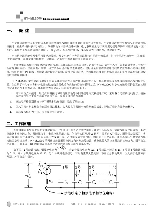
小接地电流系统发生单相接地故障后, PT 开口三角处产生零序电压。
理论分析结果是:故障线路零序电流等于非故障线路零序电流之和。
故障线路零序电流应该是最大的。
但由于实际现场CT 误差、装置内CT 误差、测量误差等原因,实际计算值可能并非最大,也可能是第二大或第三大。
- 1、下载文档前请自行甄别文档内容的完整性,平台不提供额外的编辑、内容补充、找答案等附加服务。
- 2、"仅部分预览"的文档,不可在线预览部分如存在完整性等问题,可反馈申请退款(可完整预览的文档不适用该条件!)。
- 3、如文档侵犯您的权益,请联系客服反馈,我们会尽快为您处理(人工客服工作时间:9:00-18:30)。
目录1产品介绍 ............................................................................................................................. - 2 -1.1概述 ..................................................................................................................... - 2 -1.2功能介绍 ............................................................................................................. - 2 -1.2.1单载频信号测量功能.................................................................................. - 2 -1.2.2多载频测量功能 ......................................................................................... - 2 -1.2.3单频测量功能 ............................................................................................. - 3 -1.2.4直流测量功能 ............................................................................................. - 3 -1.2.5补偿电容在线测量功能.............................................................................. - 3 -1.2.6相敏测量功能 ............................................................................................. - 3 -1.2.7阻抗在线测量功能...................................................................................... - 3 -1.2.8示波器功能 ................................................................................................. - 3 -1.2.9高压脉冲轨道电路测量功能...................................................................... - 3 -1.2.10高压脉冲和ZPW2000移频信号叠加测量功能 ............................... - 4 -1.2.11高压脉冲和中国移频信号叠加测量功能.................................................. - 4 -1.2.12调整表功能 ......................................................................................... - 4 -1.2.13数据存储功能...................................................................................... - 4 - 2技术指标 ............................................................................................................................. - 4 -2.1使用条件 ............................................................................................................. - 4 -2.2直流测项指标 ..................................................................................................... - 4 -2.3单频测量指标 ..................................................................................................... - 5 -2.4移频测量指标 ..................................................................................................... - 5 -2.4.1中国移频制式 ............................................................................................. - 5 -2.4.2UM71/ZPW-2000制式 ............................................................................... - 5 -2.5补偿电容测量指标 ............................................................................................. - 6 -2.6相敏测量指标 ..................................................................................................... - 6 -2.7阻抗测量指标 ..................................................................................................... - 6 -2.8高压脉冲轨道电路测量指标.............................................................................. - 6 -2.9电流钳性能指标 ................................................................................................. - 7 - 3产品使用 ............................................................................................................................. - 7 -3.1信号输入 ............................................................................................................. - 7 -3.1.1电压信号输入 ............................................................................................. - 7 -3.1.2电流信号输入 ............................................................................................. - 7 -3.2开机与关机 ......................................................................................................... - 7 -3.3打开背光 ............................................................................................................. - 7 -3.4系统设定 ............................................................................................................. - 8 -3.4.1自动关机时间设定...................................................................................... - 8 -3.4.2背光保持时间设定...................................................................................... - 8 -3.4.3日期时间 ..................................................................................................... - 8 -3.5屏幕亮度/对比度设定 ........................................................................................ - 8 -3.6电压和电流切换 ................................................................................................. - 8 -3.7数据锁定 ............................................................................................................. - 8 -3.8电池充电 ............................................................................................................. - 8 - 4出厂配置清单 ..................................................................................................................... - 9 - 5使用小常识 ......................................................................................................................... - 9 -5.1使用与养护 ......................................................................................................... - 9 -1 产品介绍1.1 概述ME2000H轨道电路综合测试仪是针对铁路部门而研制的多功能专用仪器,适用于电务工区日常检测和维护使用,本仪器具有体积小、精度高、操作简便等特点。