利用单臂路由实现vlan间的通信
华为单臂路由配置实例
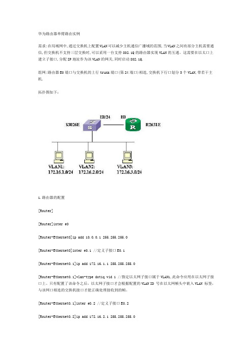
华为路由器单臂路由实例需求:在局域网中,通过交换机上配置VLAN可以减少主机通信广播域的范围,当VLAN之间有部分主机需要通信,但交换机不支持三层交换时,可以采用一台支持802.1Q的路由器实现VLAN的互通。
这需要在以太口上建立子接口,分配IP地址作为该VLAN的网关,同时启动802.1Q.组网:路由器E0端口与交换机的上行trunk端口(第24端口)相连,交换机下行口划分3个VLAN,带若干主机.拓扑图如下:1.路由器的配置[Router][Router]inter e0[Router-Ethernet0]ip add 10.0.0.1 255.255.255.0[Router-Ethernet0]inter e0.1 //定义子接口E0.1[Router-Ethernet0.1]ip add 172.16.1.1 255.255.255.0[Router-Ethernet0.1]vlan-type dot1q vid 1 //指定以太网子接口属于VLAN1,此命令应用在以太网子接口上。
只有配置了该命令之后,以太网子接口才会根据配置的VLAN ID 号在以太网帧头中嵌入VLAN 标签,与该网口相连的交换机接口才能正确处理接收到的帧。
[Router-Ethernet0.1]inter e0.2 //定义子接口E0.2[Router-Ethernet0.2]ip add 172.16.2.1 255.255.255.0[Router-Ethernet0.2]vlan-type dot1q vid 2 //指定以太网子接口属于VLAN2[Router-Ethernet0.2]inter e0.3 //定义子接口E0.3[Router-Ethernet0.3]ip add 172.16.3.1 255.255.255.0[Router-Ethernet0.3]vlan-type dot1q vid 3 //指定以太网子接口属于VLAN3[Router-Ethernet0.3]inter e0[Router-Ethernet0]undo shut% Interface Ethernet0 is up[Router-Ethernet0] //用网线将E0端口连到S3026第24端口%19:46:32: Interface Ethernet0 changed state to UP%19:46:32: Line protocol ip on interface Ethernet0, changed state to UP%19:46:32: Line protocol ip on interface Ethernet0.1, changed state to UP%19:46:32: Line protocol ip on interface Ethernet0.2, changed state to UP%19:46:32: Line protocol ip on interface Ethernet0.3, changed state to UP2.交换机的配置sysEnter system view , return user view with Ctrl+Z.[Quidway]vlan 1[Quidway-vlan1]vlan 2[Quidway-vlan2]port ethernet 0/17 to eth 0/19 eth 0/22 //将第17至19端口,和第22端口加入VLAN2 [Quidway-vlan2]vlan 3[Quidway-vlan3]port eth 0/21 //将第21端口加入VLAN2[Quidway-vlan3]inter e0/24[Quidway-Ethernet0/24]port link-type trunk //将第24端口设为trunk口[Quidway-Ethernet0/24]port trunk permit vlan all//允许所有VLAN流量通过Please wait........................................... Done. [Quidway-Ethernet0/24]dis port trunk //检验TRUNK口配置Now, the following trunking ports exist:Ethernet0/24[Quidway-Ethernet0/24]dis vlan 2 //检验VLAN2的配置VLAN ID: 2VLAN Type: staticRoute Interface: not configuredDescription: VLAN 0002Tagged Ports:Ethernet0/24Untagged Ports:Ethernet0/17 Ethernet0/18 Ethernet0/19 Ethernet0/22[Quidway-Ethernet0/24]dis vlan 3 //检验VLAN3的配置VLAN ID: 3VLAN Type: staticRoute Interface: not configuredDescription: VLAN 0003Tagged Ports:Ethernet0/24Untagged Ports:Ethernet0/213.在工作站上检查网络是否连通。
不同VLAN之间相互通信的两种方式(三层交换配置)

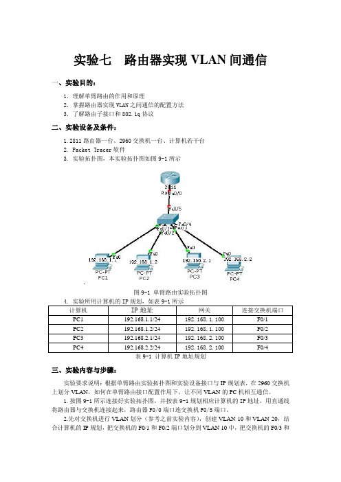
不同VLAN之间相互通信的两种方式(单臂路由、三层交换)试验环境:东郊二楼第三机房试验设备:Catalyst 2950-24(SW3)Catalyst 3750 SERIES (带两个SD接口,S8----SW-2L)计算机(PC5、PC6)。
试验目的:1、通过单臂路由实现不同VLAN之间的通信2、通过三层交换路由功能实现不同VLAN之间的通信网络拓扑图:1、单臂路由实现不同VLAN互通试验网络拓扑图2、三层交换实现不同VLAN互通实验网络拓扑图实验步骤:单臂路由实现不同VLAN互通试验步骤一、交换机SW3的具体配置(主要配置vlan和trunk接口)1、在SW3上创建vlan 100、vlan200、vlan300,名称依次为caiwu、xiaoshou、gongcheng。
(创建vlan既可以在vlan database中,也可以在全局模式下配置,本实验是在vlan database中配置的)2、在全局模式下,将f0/1 –5号端口划分到vlan 100中,f0/6–10口划分到vlan 200中,f0/11 – 15号端口划分到vlan 300中,并全部配置成access模式。
3、使用show vlan显示SW3的vlan配置信息,可以看出配置正确)4、交换机如果通过路由器实现VLAN之间的通信,需要将连接交换机的端口配置成trunk 模式,只有trunk线路才能使vlan通过。
二、路由器R2的具体配置(通过配置路由器子接口封装之后作为每一个vlan的网关)1、在路由器(R2)与交换机(SW3)的端口上配置子接口,每个子接口的IP地址是每个VLAN的网关地址(也可以理解为下一跳地址),并在子接口上封装802.1Q协议(交换机通用封装模式)。
也可以封装ISL协议(cisco专用协议,不兼容802.1Q)。
2、将PC5和PC6分别连接到交换机SW3的f0/6和f0/1上,然后配置PC5的IP地址为192.168.2.1/24,网关为192.168.2.254。
VLAN间路由-单臂路由的基本概念

VLAN间通信
VLAN 100
VLAN 200
VLAN 300
▪ 不同VLAN之间的流量不能直接跨越VLAN的边 界,需要使用路由,通过路由将报文从一个 VLAN转发到另外一个VLAN。
3
使用VLAN Trunking
VLAN 100
VLAN 200
第二种方式 单臂路由
VLAN 300
▪ 二层交换机上和路由器上配置他们之间相连的端 口使用VLAN Trunking,使多个VLAN共享同一 条物理连接到路由
VLAN20的标签
000000111111 000000bbbbbb
源
10.0.0.10
目 的
20.0.0.20
无标签
000000aaaaaa 000000111111
SW1
F0/1
F0/2
源
10.0.0.10
目 的
20.0.0.20
无标签
000000111111 000000bbbbbb
主机A VLAN 10
Vlan标识 帧头
数据
6
单臂路由的工作原理
▪ 单臂路由实现不同VLAN间通信的原理
路由器重新封装MAC地址、转换VLAN标签
源
10.0.0.10
目
的
20.0.0.20
VLAN10的标签
000000aaaaaa 000000111111
R1 F0/0
F0/24
源
10.0.0.10
目 的
20.0.0.20
单臂路由的基本概念
前言
▪ VLAN间路由就是实现不同VLAN之间的通信。单臂路由技术是指在路由器的一 个接口上通过配置子接口(或“逻辑接口”,并不存在真正物理接口)的方式 ,实现原来相互隔离的不同VLAN之间的互联互通。
实验七 VLAN之间的路由及配置单臂路由
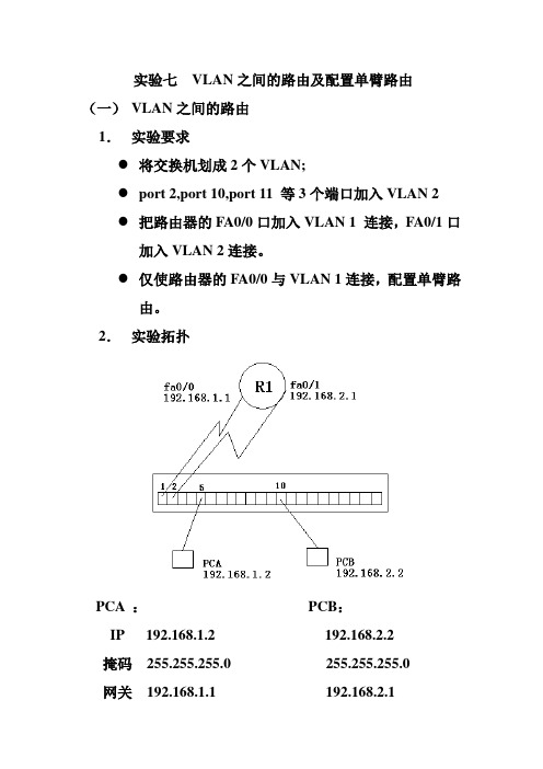
实验七VLAN之间的路由及配置单臂路由(一)VLAN之间的路由1.实验要求●将交换机划成2个VLAN;●port 2,port 10,port 11 等3个端口加入VLAN 2●把路由器的FA0/0口加入VLAN 1 连接,FA0/1口加入VLAN 2连接。
●仅使路由器的FA0/0与VLAN 1连接,配置单臂路由。
2.实验拓扑PCA :PCB:IP 192.168.1.2 192.168.2.2掩码255.255.255.0 255.255.255.0网关192.168.1.1 192.168.2.13.实验步骤Switch:#config t#int fa0/2#switchport mode access 将端口映射到VLAN2#switchport access vlan 2#exit#int fa0/10#switchport mode access#switchport access vlan 2#exit#int fa0/11#switchport mode access#switchport access vlan 2#exit#show vlanRouter:#conf t#int fa0/0#ip address 192.168.1.1 255.255.255.0#no shut#exit#int fa0/1#ip address 192.168.2.1 255.255.255.0#no shut PCA ping PCB ?(二) 单臂路由1. 实验要求这时接入VLAN1的配置正确的计算机与接入VLAN2的配置正确的计算机可以正常通信,但多浪费路由器的一个接口和交换机的一个接口,方法不可行。
将连接路由器端口Fa0/1与交换机的线断开,形成单臂路由。
2.实验拓扑3.实验步骤Switch:config tint Fa0/1switchport mode trunk 在端口上配置中继(2950) switchport trunk encapsulation dot1q 用dot1q进行封装switchport mode trunk (3560)router:config tint fa0/0no ip addressexitint fa0/1no ip addressexitint fa0/0.1router(config-subif)# encapsulation dot1q 1将子接口fa0/0.1设置为trunk,用dot1q封装,划分到VLAN1 router(config-subif)#ip address 192.168.1.1 255.255.255.0 (子接口封装后才能进行IP地址的配置)router(config-subif)#no shutrouter(config-subif)#exitrouter(config)#int fa0/0.2router(config-subif)#encapsulation dot1q 2router(config-subif)#ip address 192.168.2.1 255.255.255.0 router(config-subif)#no shutPCA ping PCB ?配置前先输入:Router#reload------------------------------------(yes/no):noSwitch#reload------------------------------------(yes/no):no。
路由器实现vlan间通信
Ping 192.168.2.2
图Ping命令测试
Tracert 192.168.2.2
图tracert命令查看路由
至此,通过以上配置和测试,成功地利用单肩路由的方法,实现了在单个路由器上完成不同VLAN之间的通信,同时,请思考还有什么方法可实现不同VLAN之间的通信。
Switch(config-if)#no shutdown
Switch(config-if)exit
Switch(config)exit
Switch#
3.配置完交换机后可以利用Show命令分别查看VLAN的信息和交换机的配置信息,以确保交换机配置正确,查看交换机的VLAN信息如图9-2所示。
图9-2 查看交换机的VLAN信息
8.在动画演示Simulation模式下,设置事件列表过滤器只显示ICMP事件,单击ADD Simple PDU按钮,在拓扑图中添加PC0向PC3发送的数据包。单击Auto Capture/ Play按钮,观察数据发送的过程。当数据包在路由器上时,双击ICMP数据报,弹出ICMP包详细的封装信息,截图,查看802.1Q的帧格式。
4.实验所用计算机的IP规划,如表9-1所示
计算机
IP地址
网关
连接交换机端口
PC1
192.168.1.1/24
192.168.1.100
F0/1
PC2
192.168.1.2/24
192.168.1.100
F0/2
PC3
192.168.2.1/24
192.168.2.100
F0/3
PC4
192.168.2.2/24
2.先对交换机进行VLAN划分(参考之前实验内容),创建VLAN 10和VLAN 20,结合计算机的IP规划,把交换机的F0/1和F0/2端口划分到VLAN 10中,把交换机的F0/3和F0/4端口划分到VLAN 20中,配置交换机的F0/5端口为trunk链路端口。
实验三 通过配置路由器或三层交换机实现VLAN间的通信

实验三实现VLAN间的通信一、通过路由器实现vlan间通信(单臂路由)实验拓扑图【准备知识】在路由器与交换机的端口上配置子接口,每个子接口的IP地址是每个VLAN的网关地址(也可以理解为下一跳地址),并在子接口上封装802.1Q协议。
也可以封装ISL协议(cisco专用协议,不兼容802.1Q)。
【实验步骤】1、交换机配置如下:Switch>enSwitch#conf tSwitch(config)#vlan 2Switch(config-vlan)#vlan 3Switch(config-vlan)#exitSwitch(config)#int fa0/2Switch(config-if)#sw ac vlan 2 //switchport access vlan 2的简写,端口fa0/2划到vlan 2中Switch(config-if)#int fa0/3Switch(config-if)#sw ac vlan 3Switch(config-if)#exitSwitch(config)#int fa0/1Switch(config-if)#switchport mode trunk //设置f0/1端口为trunk模式2、路由器配置如下:Router>enRouter#conf tRouter(config)#int fa0/0Router(config-if)#no shutdownRouter(config-if)#exitRouter(config)#int f0/0.1Router(config-subif)#encapsulation dot1q 2 //封装协议802.1Q,2为vlan 2 Router(config-subif)#ip address 192.168.1.1 255.255.255.0Router(config-subif)#exitRouter(config)#int f0/0.2Router(config-subif)#encapsulation dot1q 3 //封装协议802.1Q,3为vlan 3 Router(config-subif)#ip address 192.168.2.1 255.255.255.0Router(config-subif)#exitRouter(config)#【检测实验结果】VLAN 2中的pc1能ping 通VLAN 3中的pc2。
利用路由器实现VLAN间通信(单臂路由)
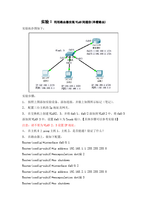
实验1 利用路由器实现VLAN间通信(单臂路由)实验拓扑图如下:实验步骤:1、按照上图添加实验设备、添加连接,并做上如图所示标记(笔记)。
2、配置三台主机的Ip地址及网关。
3、在交换机上创建VLAN2、3,并将fa0/1、fa0/2添加到VLAN 2中,将fa0/3添加到VLAN 3中,设置fa0/4为Trunk端口。
【具体步骤可以参考实验8】注意:请不要为VLAN 2、3设置IP地址。
4、在主机0上ping主机1、主机2,是否能通?验证了什么?5、在路由器上,做如下配置:Router(config)#interface fa0/0.1Router(config-subif)#ip address 192.168.1.1 255.255.255.0Router(config-subif)#encapsulation dot1Q 2Router(config-subif)#no shutdownRouter(config-subif)#interface fa0/0.2Router(config-subif)#ip address 192.168.2.1 255.255.255.0Router(config-subif)#encapsulation dot1Q 3Router(config-subif)#no shutdownRouter(config-subif)#exitRouter(config)#interface fa0/0Router(config-if)#no shutdownRouter(config-if)#endRouter#writeRouter#show ip route6、请大家思考下上面所输入的每个命令的作用是什么?请通过文字说明。
7、在主机0上ping主机1、主机2以及网关,看是否能通?【如果不同的话,请在路由器上分别Ping主机1、主机2,然后再试】七、实验说明1、思考题2、实验报告要求:实验完毕后请按照要求填写实验报告。
第十一章-单臂路由

192.168.1.254/24 up
up
GigabitEthernet0/0/0.2
192.168.2.254/24 up
up
GigabitEthernet0/0/0.up
单臂路由实现vlan间通信
查看R1的路由表 [chukou]display ip routing-table 192.168.1.0/24 Direct 0 0 GigabitEthernet0/0/0.1 192.168.1.254/32 Direct 0 0 GigabitEthernet0/0/0.1 192.168.1.255/32 Direct 0 0 GigabitEthernet0/0/0.1
单臂路由实现vlan间通信
单臂路由实现vlan间通信
原理概述: 以太网中,通常会使用vlan技术隔离二层广播域来减少广播的影响,并增
强网络的安全性和可管理性。其缺点是同时也严格隔离了不同vlan之间的 任何二层流量,使分属于不同vlan的用户不能直接相互通信。在现实中, 经常会出现某些用户需要跨越vlan实现通信的情况,单臂路由技术就是解 决vlan间通信的一种方法。 单臂路由的原理是通过一台路由器,使vlan间互通数据通过路由器进行三 层转发。如果在路由器上位每个vlan分配一个单独的路由器物理接口,随 着vlan数量的增加,必然需要更多的接口,而路由器能提供的接口数量比 较有限,所以在路由器的一个物理接口上通过配置子接口(即逻辑接口) 的方式来实现以一当多的功能。将是一种非常好的方式。路由器同一物理 接口的不同子接口作为不同vlan的默认网关,当不同vlan间的用户主机需 要通信时,只需将数据包发送给网关,网关处理后再发送到目的主机所在的 Vlan,从而实现vlan间通信。
- 1、下载文档前请自行甄别文档内容的完整性,平台不提供额外的编辑、内容补充、找答案等附加服务。
- 2、"仅部分预览"的文档,不可在线预览部分如存在完整性等问题,可反馈申请退款(可完整预览的文档不适用该条件!)。
- 3、如文档侵犯您的权益,请联系客服反馈,我们会尽快为您处理(人工客服工作时间:9:00-18:30)。
2011年3月13日星期日我做的前面配置有勿。
配置交换机1,2为trunk模式sw1#conf tEnter configuration commands, one per line. End with CNTL/Z. sw1(config)#int f0/11sw1(config-if)#switchport mode trunksw2(config)#int f0/11sw2(config-if)#switchport trunk encapsulation dot1qsw2(config-if)#switchport mode trunksw2(config)#int f0/3sw2(config-if)#switchport mode trunksw2(config-if)#switchport trunk encapsulation dot1q配vtpsw1(config)#vtp mode serversw1(config)#vtp domain lzhChanging VTP domain name from zhangle to lzhsw1(config)#vtp password 123{配不上密码}sw2#vlan databasesw2(vlan)#vtp clientsw2(vlan)#vtp domain lzh2Changing VTP domain name from NULL to lzh2sw2(vlan)#vtp passwsw2(vlan)#vtp password 123456Setting device VLAN database password to 123456.sw1#vlan database (注:2950的交换机只能在database下加密)sw1(vlan)#vtp password 123Setting device VLAN databse password to 123.sw1(vlan)#vtp pruningPruning switched ONsw1(vlan)#vtp pruning ?v2-mode Set the administrative domain to V2 mode.<cr>sw1(vlan)#vtp pruning v2-modePruning already switched on.V2 mode enabled.sw1(vlan)#exit(配vlan)(配完SW1在SW2上看不出同步?)sw1#vlan database(早期的交换机要进入database中)sw1(vlan)#vlan 10 name ITAPPLY completed.Exiting....(在SW1是的与PC1相连的接口上配接入模式并划入一个VLAN中)sw1#conf tsw1(config)#int f0/3sw1(config-if)#switchport mode accesssw1(config-if)#switchport access vlan 10sw1(config-if)#endsw1#05:31:30: %SYS-5-CONFIG_I: Configured from console by console sw1#sh vlan briVLAN Name Status Ports---- -------------------------------- --------- -------------------------------1 default active Fa0/1, Fa0/2, Fa0/4, Fa0/5Fa0/6, Fa0/7, Fa0/8, Fa0/9Fa0/10, Fa0/1210 IT active Fa0/311 VLAN0011 active12 VLAN0012 active13 VLAN0013 active14 VLAN0014 active15 VLAN0015 active16 VLAN0016 active17 VLAN0017 active18 VLAN0018 active19 VLAN0019 active20 ITAA active1002 fddi-default active1003 trcrf-default active1004 fddinet-default active1005 trbrf-default activesw1#(同上)sw2#conf tEnter configuration commands, one per line. End with CNTL/Z. sw2(config)#int f0/17sw2(config-if)#swsw2(config-if)#switchport mode accesssw2(config-if)#switchport access vlan 10(配子接口。
目地是充当网关)Router(config)#int e0/0.10Router(config-subif)#enRouter(config-subif)#encapsulation dot1q 10Router(config-subif)#ip add 172.17.10.1 255.255.255.0Router(config)#int e0/0.20Router(config-subif)#encapsulation dot1q 20Router(config-subif)#ip add 172.17.20.10 255.255.255.0Router(config-subif)#no shuRouter(config-subif)#endRouter#sh ip int briInterface IP-Address OK? Method Status Protocol Ethernet0/0 unassigned YES unset up up Ethernet0/0.10 172.17.10.1 YES manual up up Ethernet0/0.20 172.17.20.10 YES manual up up Serial0/0 unassigned YES unset administratively down down Serial0/1 unassigned YES unset administratively down down Router#(配网关)pc1(config)#ip default-gateway 192.168.1.1pc2(config)#ip default-gateway 10.1.1.1(注:本实验错误的反PC1,PC2配在一个VLAN中)sw2#vlan databasesw2(vlan)#no vlan 10Deleting VLAN 10...(老师改的)sw1#show ip int briefInterface IP-Address OK? Method Status Protocol Vlan1 unassigned YES unset administratively down down FastEthernet0/1 unassigned YES unset down down FastEthernet0/2 unassigned YES unset down down FastEthernet0/3 unassigned YES unset up up FastEthernet0/4 unassigned YES unset down down FastEthernet0/5 unassigned YES unset down down FastEthernet0/6 unassigned YES unset down down FastEthernet0/7 unassigned YES unset down down FastEthernet0/8 unassigned YES unset down down FastEthernet0/9 unassigned YES unset down down FastEthernet0/10 unassigned YES unset down down FastEthernet0/11 unassigned YES unset up up FastEthernet0/12 unassigned YES unset down down sw1#show vlansw1#show vlanVLAN Name Status Ports---- -------------------------------- --------- -------------------------------1 default active Fa0/1, Fa0/2, Fa0/4, Fa0/5Fa0/6, Fa0/7, Fa0/8, Fa0/9Fa0/10, Fa0/1210 IT active Fa0/311 VLAN0011 active12 VLAN0012 active13 VLAN0013 active14 VLAN0014 active15 VLAN0015 active16 VLAN0016 active17 VLAN0017 active18 VLAN0018 active19 VLAN0019 active20 ITAA active1002 fddi-default active1003 trcrf-default active1004 fddinet-default active1005 trbrf-default activeVLAN Type SAID MTU Parent RingNo BridgeNo Stp BrdgMode Trans1 Trans2 ---- ----- ---------- ----- ------ ------ -------- ---- -------- ------ ------1 enet 100001 1500 - - - - - 0 010 enet 100010 1500 - - - - - 0 011 enet 100011 1500 - - - - - 0 012 enet 100012 1500 - - - - - 0 013 enet 100013 1500 - - - - - 0 014 enet 100014 1500 - - - - - 0 015 enet 100015 1500 - - - - - 0 016 enet 100016 1500 - - - - - 0 017 enet 100017 1500 - - - - - 0 018 enet 100018 1500 - - - - - 0 019 enet 100019 1500 - - - - - 0 020 enet 100020 1500 - - - - - 0 01002 fddi 101002 1500 - - - - - 0 01003 trcrf 101003 4472 1005 3276 - - srb 0 01004 fdnet 101004 1500 - - - ieee - 0 01005 trbrf 101005 4472 - - 15 ibm - 0 0VLAN AREHops STEHops Backup CRFVLAN AREHops STEHops Backup CRF---- ------- ------- ----------1003 0 0 offsw1#show int f0/11 switchportName: Fa0/11Switchport: EnabledAdministrative Mode: trunkOperational Mode: trunkAdministrative Trunking Encapsulation: dot1qOperational Trunking Encapsulation: dot1qNegotiation of Trunking: OnAccess Mode VLAN: 1 (default)Trunking Native Mode VLAN: 1 (default)Trunking VLANs Enabled: ALLPruning VLANs Enabled: 2-1001Protected: falseVoice VLAN: none (Inactive)Appliance trust: nonesw1#sw1#show mac-address-table (看SW1的MAC是不是学到PC1的MAC) Mac Address Table------------------------------------------Vlan Mac Address Type Ports---- ----------- ---- -----1 000a.f429.eb0b DYNAMIC Fa0/1110 000a.f429.eb0b DYNAMIC Fa0/1110 0010.7b39.f4b9 DYNAMIC Fa0/3Total Mac Addresses for this criterion: 3sw1#sw2#sw2#show macsw2#show mac-address-table (看SW2的MAC是不是学到PC2的MAC)Dynamic Address Count: 4Secure Address Count: 0Static Address (User-defined) Count: 0System Self Address Count: 51Total MAC addresses: 55Maximum MAC addresses: 8192Non-static Address Table:Destination Address Address Type VLAN Destination Port------------------- ------------ ---- --------------------0005.74ac.694b Dynamic 1 FastEthernet0/110008.e354.6de0 Dynamic 1 FastEthernet0/30010.7b39.f4b9 Dynamic 10 FastEthernet0/110010.7b7f.7dc0 Dynamic 30 FastEthernet0/17sw2#show int f0/11 switchportName: Fa0/11Switchport: EnabledAdministrative mode: trunkOperational Mode: trunkAdministrative Trunking Encapsulation: dot1qOperational Trunking Encapsulation: dot1qNegotiation of Trunking: DisabledAccess Mode VLAN: 0 ((Inactive)) Trunking Native Mode VLAN: 1 (default) Trunking VLANs Enabled: ALLTrunking VLANs Active: 1-4,10,30,100 Pruning VLANs Enabled: 2-1001Priority for untagged frames: 0Override vlan tag priority: FALSEVoice VLAN: noneAppliance trust: noneSelf Loopback: Nosw2#show int f0/3 switchportName: Fa0/3Switchport: EnabledAdministrative mode: trunkOperational Mode: trunkAdministrative Trunking Encapsulation: dot1q Operational Trunking Encapsulation: dot1q Negotiation of Trunking: DisabledAccess Mode VLAN: 0 ((Inactive)) Trunking Native Mode VLAN: 1 (default) Trunking VLANs Enabled: ALLTrunking VLANs Active: 1-4,10,30,100 Pruning VLANs Enabled: 2-1001Priority for untagged frames: 0Override vlan tag priority: FALSEVoice VLAN: noneAppliance trust: noneSelf Loopback: Nosw2#Router>enRouter>enableRouter#Router#show ip int briefInterface IP-Address OK? Method Status Protocol Ethernet0/0 unassigned YES unset up up Ethernet0/0.10 172.17.10.1 YES manual up up Ethernet0/0.20 172.17.20.10 YES manual up up Serial0/0 unassigned YES unset administratively down down Serial0/1 unassigned YES unset administratively down downRouter#conf tEnter configuration commands, one per line. End with CNTL/Z.Router(config)#int e0/0.10Router(config-subif)#encapsulation dot1Q 10Router(config-subif)#ip address 192.168.1.1 255.255.255.0Router(config-subif)#endRouter#*Mar 1 06:57:13.224: %SYS-5-CONFIG_I: Configured from console by consolepng Router#pingRouter#ping 192.168.1.11Type escape sequence to abort.Sending 5, 100-byte ICMP Echos to 192.168.1.11, timeout is 2 seconds:..!!!Success rate is 60 percent (3/5), round-trip min/avg/max = 4/4/4 msRouter#ping 192.168.1.11Type escape sequence to abort.Sending 5, 100-byte ICMP Echos to 192.168.1.11, timeout is 2 seconds:!!!!!Success rate is 100 percent (5/5), round-trip min/avg/max = 4/4/4 ms Router#ping 192.168.1.11Type escape sequence to abort.Sending 5, 100-byte ICMP Echos to 192.168.1.11, timeout is 2 seconds:!!!!!Success rate is 100 percent (5/5), round-trip min/avg/max = 4/4/4 ms Router#conf tEnter configuration commands, one per line. End with CNTL/Z.Router(config)#endRouter#Router#ping 192.168.1.11Type escape sequence to abort.Sending 5, 100-byte ICMP Echos to 192.168.1.11, timeout is 2 seconds:!!!!!Success rate is 100 percent (5/5), round-trip min/avg/max = 4/4/8 ms Router#*Mar 1 06:57:41.266: %SYS-5-CONFIG_I: Configured from console by console Router#。