实验5 OSPF单区域
实验五 动态路由(RIP、单区域OSPF 配置)
实验五动态路由(RIP、单区域OSPF 配置)
****注意:本实验报告要求以实验小组为单位,每小组出具一份电子文档***** 班级:小组:成员学号:姓名:
一、实验目的
1、熟悉和掌握对路由器的基本配置。
2、熟悉和掌握对路由器的端口配置。
3、熟悉和掌握RIP、单区域OSPF 配置动态路由配置。
4、不连续网络RIP、单区域OSPF 配置实验设计与配置
二、实验环境
1、PC机,windows环境,超级终端、Telnet程序
2、实验室Pack一组
3、配置线、网线(直通)等
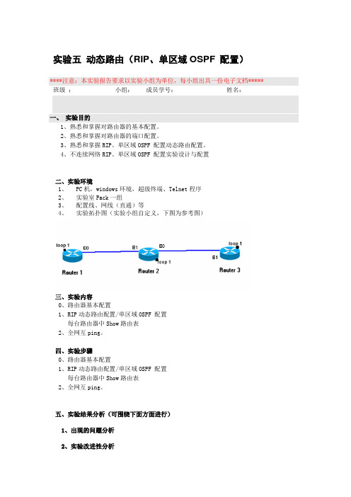
4、实验拓扑图(实验小组自定义,下图为参考图)
三、实验内容
0、路由器基本配置
1、RIP动态路由配置/单区域OSPF 配置
每台路由器中Show路由表
2、全网互ping。
四、实验步骤
0、路由器基本配置
1、RIP动态路由配置/单区域OSPF 配置
每台路由器中Show路由表
2、全网互ping。
五、实验结果分析(可围绕下面方面进行)
1、出现的问题分析
2、实验改进性分析。
OSPF单区域配置

OSPF单区域配置【学习日标】掌挥OSPF中Router ID 的配置方法掌握OSPF的配置力法掌握通过display命令查看OSPP运行状态的方法掌握使用OSPF发布缺省路由的方法掌握修改OSPF hello 和dead 时间的配置方法学握OSPF 路由优先级的修改力法【理论知识】OSPF是由IFIF 开发的基J链路状念的自治系统内部路由协议,用来代替RIP 路由协议自身的算法限.与距离矢量协议不同,链路状态路由协议使用Dijkstra 的最短路径优先算法计算和选择路由。
OSPF 协议在有组播发送能力的链路层上以组播地址发送协议包,即达到了节约资源的目的,有最大限度地减少了对其他网络设备的干扰.【实验拓扑】步骤1.按照实验拓扑图规划IP 地址步骤2。
配置OSPF 路由协议步骤3。
在OSPP中下发默认路由步骤4.查看R1的路由表、OSPP 邻居状态和链路状态数据库步骤5。
在R2上修改OSPF HELO和DEAD时间的配置方法并查看OSPF的邻居状态步骤6.修改OSPF 优先级控制DR BDR 的选举【操作步骤】步骤1。
按照实验拓扑图规划IP地址查看接口ip地址配置[Huawei] sysname R1[RI]int loo 0[R1-LoopBack0] ip add 1。
1。
1。
132[R1-LoopBack0] int g0/0/0[Rl—GigabitEthernet0/0/01ip add 12。
1。
1。
124[Huawei]sys R2[R2]int g0/0/0[R2-Gigabi tEthernet0/0/0]ip add 12.1.1.2 255.255。
255。
[R2-Gigabi tEthernet0/0/0]int loo 0[R2—LoopBack0] ip add 2.2。
2.2 32[R2-LoopBack0] int g0/0/1[R2-GigabitEthernet0/0/1] ip add 23。
计算机网络实验_实验5 OSPF路由协议实验_实验56 OSPF协议路由的计算_

北航计算机网络实验实验5.6OSPF协议的路由计算OSPF协议的路由计算⏹SPF算法和COST值⏹区域内路由的计算⏹区域间路由的计算--骨干区域和虚连接⏹区域外路由的计算--与自治系统外部通信SPF算法LSDBLSA 的RTA LSA 的RTBLSA 的RTCLSA 的RTD(二)每台路由器的链路状态数据库(一)网络的拓朴结构CABD123CAB D 123CAB D 123CABD123(四)每台路由器分别以自己为根节点计算最短路径树(三)由链路状态数据库得到的带权有向图CABD1235RTCRTD3215RTBRTASPF算法和COST值⏹SPF算法也被称为Dijkstra算法,是OSPF路由协议的基础。
☐SPF算法将每一个路由器作为根(Root)来计算到每一个目的地路由器之间的距离,每一个路由器根据一个统一的数据库会计算出路由域的拓扑结构图,该结构图类似于一棵树,在SPF算法中,被称为最短路径树。
⏹在OSPF路由协议中,最短路径树的树干长度,即OSPF路由器至每一个目的地路由器的距离,称为OSPF的Cost值。
☐Cost值应用于每一个启动了OSPF的链路,它是一个16bit的整数,范围是1~65535。
Cost值的计算方法⏹计算方法108/bandwidth☐56-kbps serial link = 1785☐10M Ethernet = 10☐64-kbps serial link = 1562☐T1 (1.544-Mbps serial link) = 64⏹用户可以手动调节链路Cost,缺省情况下,接口按照当前的波特率自动计算开销区域内路由的计算S1Vlan2:10.1.1.2/24Vlan2:30.1.1.2/24E1:30.1.1.1/24Vlan3:40.1.1.1/24E0:40.1.1.2/24R1R2AREA 0E0:10.1.1.1/24S0:20.1.1.1/24S0:20.1.1.2/24E0/1E0/24E0/1S2100200300500。
单区域的OSPF协议配置实验报告

Switch(config-router)#network 192.168.1.00.0.0.255 area 0 !声明直连网段,并分配区域号
Switch(config-router)#network 192.168.4.00.0.0.255 area 0
RouteB(config-router)# end
(6)验证三台路由设备的路由表,查看是否自动学习了其他网段的路由信息。
Switch#show ip route //查看路由表
routerA#show ip router
routerB#show ip router
(7)测试网络的连通性:
C:\>ping 192.168.3.2 //在PCA上ping PC2,能ping通,说明网络连通
实验过程及数据记录
Switch(config-if)#no shutdown //激活此接口
Switch(config-if)#exit
Switch(config)#interface vlan 40
Switch(config-if)#ip address 192.168.4.1 255.255.255.0 //给vlan 40配置IP地址
实验
设备及器材
S3550交换机(1台)、R2632路由器(2台)、计算机(2台)、配置线缆(1根)、直连线(3根)V35线缆(1根)
实验过程及数据记录
(1)如图,配置PCA和PCB的IP地址、子网掩码和网关。
(2).Switch上的基础配置:
Switch(config)#vlan 10 //创建vlan10
RouteA(config-if) #no shutdown
实验5_OSPF协议在线实验报告

实验五OSPF协议分析
1.查看R2的OSPF的邻接信息,写出其命令和显示的结果:
2.将R1的router id 更改为3.3.3.3,写出其命令。
显示OSPF的概要信息,查看此更改是否生效。
如果没有生效,如何使其生效?
3.6.1 OSPF协议报文格式
3.分析截获的报文,可以看到OSPF的五种协议报文,请写出这五种协议报文的名称。
并选择一条Hello报文,写出整个报文的结构(OSPF首部及Hello报文体)。
4.分析OSPF协议的头部,OSPF协议中Router ID的作用是什么?它是如何产生的?
5.分析截获的一条LSUpdate报文,写出该报文的首部,并写出该报文中有几条LSA?以及相应LSA的种类。
3.6.2 OSPF报文交互过程
6.结合截获的报文和DD报文中的字段(MS,I,M),写出DD主从关系的协商过程和协商结果。
7.结合截获的报文和DD报文中的字段(MS,I,M,Seq),写出LSA摘要信息交互的过程,并描述其隐含确认与可靠传输机制是如何起作用的。
8.结合截获的一组相关的LSR、LSU和LSAck报文,具体描述OSPF协议报文交互过程中确保可靠传输的机制。
3.6.3 邻居状态机
9.请根据debug显示信息,画出R1上的OSPF邻居状态转移图。
计算机网络原理实验【OSPF单区域】

实验 5 报告 学号姓名 课堂号 01 实验日期 实验名称OSPF 单区域 实验用时 同组人指导教师 一、实验目的通过实验理解并掌握OSPF 路由选择协议的原理及配置方法,掌握使用OSPF 动态路由实现网络的连通性。
二、实验要求1.通过实验理解并掌握动态路由选择协议OSPF 的原理及配置方法,2.理解并掌握查看路由器系统及配置信息;3.掌握OSPF 路由方式实现网络的连通性。
三、实验环境(设备)实验设备路由器4台,三层交换机2台,PC4台,直连线4根,交叉线2根,V.35 DCE/DTE 电缆3根IP 地址规划,如下表: S1(C) S0 S1(C) S0 S2(C)S0 R2620-1 R2624-2 F0 S3550-1 S3550-2 F1 Area0 R2624-1 Vlan5 Vlan10 R2620-2 PC1 PC2 PC3 PC4 F0 F0设备名接口IP地址R2624-1 S0 200.20.100.1/24 S1 200.20.110.1/24 S2 200.20.120.1/24R2624-2 F0 192.168.10.2/24 F1 192.168.5.2/24 S0 200.20.120.2/24R2620-1 S1 200.20.100.2/24 F0 200.10.10.1/24R2620-2 S0 200.20.110.2/24 F0 200.10.100.1/24S3550-1 VLAN 5 192.168.5.1/24S3550-2 VLAN 10 192.168.10.1/241、单击一个路由设备如:R2624-1/2 (4口) R2620-1/2(1口)用ctrl+C中断要你输入的内容,进入Red-Giant>2、路由器R2624-1配置(1)配置R2624-1的串口s0,s1和s2R2624-1(config)#interface serial 0R2624-1(config-if)#ip address 200.20.100.1 255.255.255.0R2624-1(config-if)#no shutdownR2624-1(config)#interface serial 1R2624-1(config-if)#ip address 200.20.110.1 255.255.255.0R2624-1(config-if)#clock rate 64000(配置时钟,注意是DCE端)R2624-1(config-if)#no shutdownR2624-1(config)#interface serial 2R2624-1(config-if)#ip address 200.20.120.1 255.255.255.0R2624-1(config-if)#clock rate 64000(配置时钟,注意是DCE端)R2624-1(config-if)#no shutdown(2)验证路由器接口及串口配置:R2624-1#Show ip interface brief(3)配置ospf路由R2624-1(config)#router ospf 100R2624-1(config-osp)f#network 200.20.100.0 0.0.0.255 area 0 R2624-1(config-osp)f#network 200.20.110.0 0.0.0.255 area 0 R2624-1(config-osp)f#network 200.20.120.0 0.0.0.255 area 0 R2624-1#show ip route(查看路由)3、路由器R2624-2配置(1)配置2624-2的串口s0配置2624-2的串口s0R2624-2(config)#interface serial 0R2624-2(config-if)#ip address 200.20.120.2 255.255.255.0R2624-2(config-if)#no shutdown(2)配置以太网接口F0和f1R2624-2(config)#interface f0R2624-2(config-if)#ip address 192.168.10.2 255.255.255.0R2624-2(config-if)#no shutdownR2624-2(config)#interface f1R2624-2(config-if)#ip address 192.168.5.2 255.255.255.0R2624-2(config-if)#no shutdown(4)配置ospf路由R2624-2(config)#router ospf 100R2624-2(config-osp)f#network 192.168.10.0 0.0.0.255 area 0R2624-2(config-osp)f#network 192.168.5.0 0.0.0.255 area 0R2624-2(config-osp)f#network 200.20.120.0 0.0.0.255 area 0R2624-2#show ip route(查看路由)4、路由器R2620-1配置R2620-1>enableR2620-1#conf terEnter configuration commands, one per line. End with CNTL/Z. R2620-1(config)#hostname R2620-1R2620-1(config)#(1)查看路由器接口状态R2620-1#show ip int brief(2)配置接口f0R2620-1#conf terEnter configuration commands, one per line. End with CNTL/Z. R2620-1(config)#interface fa 0R2620-1(config-if)#ip address 200.10.10.1 255.255.255.0R2620-1(config-if)#no shutdown(3)配置串口s1R2620-1(config)#inter serial 1R2620-1(config-if)#ip address 200.20.100.2 255.255.255.0R2620-1(config-if)#clock rate 64000(配置时钟,注意是DCE端)R2620-1(config-if)#no shutdown(4)验证接口、串口配置R2620-1#Show ip interface brief(5)ospf配置R2620-1(config)#router ospf 100R2620-1(config-ospf)#network 200.10.10.0 0.0.0.255 area 0R2620-1(config-ospf)#network 200.20.100.0 0.0.0.255 area 05、路由器R2620-2配置R2620-2>enableR2620-2#conf terEnter configuration commands, one per line. End with CNTL/Z. R2620-2(config)#hostname R2620-2R2620-2(config)#(1)查看路由器接口状态R2620-2#show ip int brief(2)配置接口f0R2620-2#conf terEnter configuration commands, one per line. End with CNTL/Z. R2620-2(config)#interface fa 0R2620-2(config-if)#ip address 200.10.100.1 255.255.255.0R2620-2(config-if)#no shutdown(3)配置串口s0R2620-2(config)#inter serial 0R2620-2(config-if)#ip address 200.20.110.2 255.255.255.0R2620-2(config-if)#no shutdown(4)验证接口、串口配置R2620-2#Show ip interface brief(5)ospf配置R2620-1(config)#router ospf 100R2620-1(config-ospf)#network 200.10.100.0 0.0.0.255 area 0R2620-1(config-ospf)#network 200.20.110.0 0.0.0.255 area 06、配置S3550-1S3550-1#conf tS3550-1(config)#vlan 5S3550-1(config-vlan)#exitS3550-1(config)#interface renge f 0/10-15S3550-1(config-if-range)#switchport access vlan 5S3550-1(config)#interface vlan 5S3550-1(config-if)#ip address 192.168.5.1 255.255.255.0S3550-1(config-if)#no shutdownS3550-1(config)#router ospfS3550-1(config-ospf)#network 192.168.5.1 0.0.0.255 area 07、配置S3550-2S3550-2#conf tS3550-2(config)#vlan 10S3550-2(config-vlan)#exitS3550-2(config)#interface renge f 0/10-15S3550-2(config-if-range)#switchport access vlan 10S3550-2(config)#interface vlan 10S3550-2(config-if)#ip address 192.168.10.1 255.255.255.0S3550-2(config-if)#no shutdownS3550-2(config)#router ospfS3550-2(config-ospf)#network 192.168.10.1 0.0.0.255 area 08、测试•断开防火墙•断开第1块网卡连接•将PC1的内网卡 IP设置成192.168.5.20,掩码255.255.255.0 网关192.168.5.1 •将PC2的内网卡 IP设置成192.168.10.2,掩码255.255.255.0网关192.168.10.1 •将PC3的内网卡 IP设置成200.10.10.10,掩码255.255.255.0网关200.10.10.1 •将PC4的内网卡 IP设置成200.10.100.10,掩码255.255.255.0网关200.10.100.1 (请注意:R2620和主机之间的连接需要使用交叉线)•测试互通性附录:可使用的验证命令1.show run2.show ip interface brife3.show ip route4.Show ip ospf5.Show ip ospf border-routers6.Show ip ospf interface7.Show ip ospf neighbor五、实验记录在完成相应的配置后,以下是所有设备的路由信息【S3550-1】s3550-1>en 14Password:s3550-1#show ip routeType: C - connected, S - static, R - RIP, O - OSPF, IA - OSPF inter areaN1 - OSPF NSSA external type 1, N2 - OSPF NSSA external type 2E1 - OSPF external type 1, E2 - OSPF external type 2Type Destination IP Next hop Interface Distance Metric Status---- ------------------ --------------- --------- -------- -------- --------C 192.168.5.0/24 0.0.0.0 VL5 0 0 ActiveO 192.168.10.0/24 192.168.5.2 VL5 110 2 ActiveO 200.10.10.0/24 192.168.5.2 VL5 110 98 ActiveO 200.10.100.0/24 192.168.5.2 VL5 110 98 ActiveO 200.20.100.0/24 192.168.5.2 VL5 110 97 ActiveO 200.20.110.0/24 192.168.5.2 VL5 110 97 ActiveO 200.20.120.0/24 192.168.5.2 VL5 110 49 Actives3550-1#******************************************************************************** 【S3550-2】s3550-2#show ip routeType: C - connected, S - static, R - RIP, O - OSPF, IA - OSPF inter areaN1 - OSPF NSSA external type 1, N2 - OSPF NSSA external type 2E1 - OSPF external type 1, E2 - OSPF external type 2Type Destination IP Next hop Interface Distance Metric Status---- ------------------ --------------- --------- -------- -------- --------O 192.168.5.0/24 192.168.10.5 VL10 110 2 ActiveC 192.168.10.0/24 0.0.0.0 VL10 0 0 ActiveO 200.10.10.0/24 192.168.10.5 VL10 110 98 ActiveO 200.10.100.0/24 192.168.10.5 VL10 110 98 ActiveO 200.20.100.0/24 192.168.10.5 VL10 110 97 ActiveO 200.20.110.0/24 192.168.10.5 VL10 110 97 ActiveO 200.20.120.0/24 192.168.10.5 VL10 110 49 Actives3550-2#******************************************************************************** ******************************************************************************** 【R2624-1】r2624-1>enr2624-1#show ip routeCodes: C - connected, S - static, R - RIPO - OSPF, IA - OSPF inter areaE1 - OSPF external type 1, E2 - OSPF external type 2Gateway of last resort is not setO 192.168.10.0/24 [110/870] via 200.20.120.2, 00:06:06, Serial2O 192.168.5.0/24 [110/870] via 200.20.120.2, 00:06:06, Serial2C 200.20.120.0/24 is directly connected, Serial2O 200.10.100.0/24 [110/49] via 200.20.110.2, 00:06:06, Serial1C 200.20.110.0/24 is directly connected, Serial1C 200.20.100.0/24 is directly connected, Serial0O 200.10.10.0/24 [110/49] via 200.20.100.2, 00:06:06, Serial0r2624-1#******************************************************************************** 【R2624-2】r2624-2#show ip routeCodes: C - connected, S - static, R - RIPO - OSPF, IA - OSPF inter areaE1 - OSPF external type 1, E2 - OSPF external type 2Gateway of last resort is not setC 192.168.10.0/24 is directly connected, FastEthernet0C 192.168.5.0/24 is directly connected, FastEthernet1C 200.20.120.0/24 is directly connected, Serial0O 200.10.100.0/24 [110/97] via 200.20.120.1, 00:06:23, Serial0O 200.20.110.0/24 [110/96] via 200.20.120.1, 00:06:23, Serial0O 200.20.100.0/24 [110/96] via 200.20.120.1, 00:06:23, Serial0O 200.10.10.0/24 [110/97] via 200.20.120.1, 00:06:23, Serial0r2624-2#******************************************************************************** ******************************************************************************** 【2620-1】R2620-1>enR2620-1#show ip routeCodes: C - connected, S - static, R - RIPO - OSPF, IA - OSPF inter areaE1 - OSPF external type 1, E2 - OSPF external type 2Gateway of last resort is not setO 192.168.10.0/24 [110/918] via 200.20.100.1, 00:06:43, Serial1O 192.168.5.0/24 [110/918] via 200.20.100.1, 00:06:43, Serial1O 200.20.120.0/24 [110/917] via 200.20.100.1, 00:06:43, Serial1O 200.10.100.0/24 [110/97] via 200.20.100.1, 00:06:43, Serial1O 200.20.110.0/24 [110/96] via 200.20.100.1, 00:06:43, Serial1C 200.20.100.0/24 is directly connected, Serial1C 200.10.10.0/24 is directly connected, FastEthernet0R2620-1#******************************************************************************** ******************************************************************************** 【R2620-2】R2620-2#sho ip routCodes: C - connected, S - static, R - RIPO - OSPF, IA - OSPF inter areaE1 - OSPF external type 1, E2 - OSPF external type 2Gateway of last resort is not setO 192.168.10.0/24 [110/918] via 200.20.110.1, 00:07:09, Serial0 O 192.168.5.0/24 [110/918] via 200.20.110.1, 00:07:09, Serial0 O 200.20.120.0/24 [110/917] via 200.20.110.1, 00:07:09, Serial0 C 200.10.100.0/24 is directly connected, FastEthernet0C 200.20.110.0/24 is directly connected, Serial0O 200.20.100.0/24 [110/96] via 200.20.110.1, 00:07:09, Serial0 O 200.10.10.0/24 [110/97] via 200.20.110.1, 00:07:09, Serial0 R2620-2#六、实验结果及其分析以下是测试通讯是否畅通的结果,以地址为192.168.10.1为例Microsoft Windows XP [版本5.1.2600](C) 版权所有1985-2001 Microsoft Corp.C:\Documents and Settings\Administrator>ping 192.168.10.1Pinging 192.168.10.1 with 32 bytes of data:Reply from 192.168.10.1: bytes=32 time=3ms TTL=63Reply from 192.168.10.1: bytes=32 time<1ms TTL=63Reply from 192.168.10.1: bytes=32 time<1ms TTL=63Reply from 192.168.10.1: bytes=32 time<1ms TTL=63Ping statistics for 192.168.10.1:Packets: Sent = 4, Received = 4, Lost = 0 (0% loss), Approximate round trip times in milli-seconds:Minimum = 0ms, Maximum = 3ms, Average = 0msC:\Documents and Settings\Administrator>ping 192.168.10.5Pinging 192.168.10.5 with 32 bytes of data:Reply from 192.168.10.5: bytes=32 time<1ms TTL=255 Reply from 192.168.10.5: bytes=32 time<1ms TTL=255 Reply from 192.168.10.5: bytes=32 time<1ms TTL=255 Reply from 192.168.10.5: bytes=32 time<1ms TTL=255Ping statistics for 192.168.10.5:Packets: Sent = 4, Received = 4, Lost = 0 (0% loss), Approximate round trip times in milli-seconds:Minimum = 0ms, Maximum = 0ms, Average = 0msC:\Documents and Settings\Administrator>ping 192.168.5.1Pinging 192.168.5.1 with 32 bytes of data:Reply from 192.168.5.1: bytes=32 time<1ms TTL=64 Reply from 192.168.5.1: bytes=32 time<1ms TTL=64 Reply from 192.168.5.1: bytes=32 time<1ms TTL=64 Reply from 192.168.5.1: bytes=32 time<1ms TTL=64Ping statistics for 192.168.5.1:Packets: Sent = 4, Received = 4, Lost = 0 (0% loss), Approximate round trip times in milli-seconds:Minimum = 0ms, Maximum = 0ms, Average = 0msC:\Documents and Settings\Administrator>ping 192.168.5.20Pinging 192.168.5.20 with 32 bytes of data:Reply from 192.168.5.20: bytes=32 time<1ms TTL=128 Reply from 192.168.5.20: bytes=32 time<1ms TTL=128 Reply from 192.168.5.20: bytes=32 time<1ms TTL=128 Reply from 192.168.5.20: bytes=32 time<1ms TTL=128Ping statistics for 192.168.5.20:Packets: Sent = 4, Received = 4, Lost = 0 (0% loss), Approximate round trip times in milli-seconds:Minimum = 0ms, Maximum = 0ms, Average = 0msC:\Documents and Settings\Administrator>ping 200.20.120.1Pinging 200.20.120.1 with 32 bytes of data:Reply from 200.20.120.1: bytes=32 time=21ms TTL=254 Reply from 200.20.120.1: bytes=32 time=18ms TTL=254 Reply from 200.20.120.1: bytes=32 time=19ms TTL=254 Reply from 200.20.120.1: bytes=32 time=18ms TTL=254Ping statistics for 200.20.120.1:Packets: Sent = 4, Received = 4, Lost = 0 (0% loss), Approximate round trip times in milli-seconds:Minimum = 18ms, Maximum = 21ms, Average = 19msC:\Documents and Settings\Administrator>ping 200.20.110.1Pinging 200.20.110.1 with 32 bytes of data:Reply from 200.20.110.1: bytes=32 time=21ms TTL=254Reply from 200.20.110.1: bytes=32 time=19ms TTL=254 Reply from 200.20.110.1: bytes=32 time=19ms TTL=254Ping statistics for 200.20.110.1:Packets: Sent = 4, Received = 4, Lost = 0 (0% loss), Approximate round trip times in milli-seconds:Minimum = 19ms, Maximum = 21ms, Average = 19msC:\Documents and Settings\Administrator>ping 200.10.100.1Pinging 200.10.100.1 with 32 bytes of data:Reply from 200.10.100.1: bytes=32 time=44ms TTL=253 Reply from 200.10.100.1: bytes=32 time=37ms TTL=253 Reply from 200.10.100.1: bytes=32 time=37ms TTL=253 Reply from 200.10.100.1: bytes=32 time=37ms TTL=253Ping statistics for 200.10.100.1:Packets: Sent = 4, Received = 4, Lost = 0 (0% loss), Approximate round trip times in milli-seconds:Minimum = 37ms, Maximum = 44ms, Average = 38msC:\Documents and Settings\Administrator>ping 200.10.100.10Pinging 200.10.100.10 with 32 bytes of data:Reply from 200.10.100.10: bytes=32 time=37ms TTL=125 Reply from 200.10.100.10: bytes=32 time=37ms TTL=125Reply from 200.10.100.10: bytes=32 time=36ms TTL=125Ping statistics for 200.10.100.10:Packets: Sent = 4, Received = 4, Lost = 0 (0% loss), Approximate round trip times in milli-seconds:Minimum = 36ms, Maximum = 37ms, Average = 36ms C:\Documents and Settings\Administrator>ping 200.20.100.2 Pinging 200.20.100.2 with 32 bytes of data:Reply from 200.20.100.2: bytes=32 time=39ms TTL=253 Reply from 200.20.100.2: bytes=32 time=37ms TTL=253 Reply from 200.20.100.2: bytes=32 time=37ms TTL=253 Reply from 200.20.100.2: bytes=32 time=37ms TTL=253Ping statistics for 200.20.100.2:Packets: Sent = 4, Received = 4, Lost = 0 (0% loss), Approximate round trip times in milli-seconds:Minimum = 37ms, Maximum = 39ms, Average = 37ms C:\Documents and Settings\Administrator>ping 200.10.10.10 Pinging 200.10.10.10 with 32 bytes of data:Reply from 200.10.10.10: bytes=32 time=38ms TTL=125 Reply from 200.10.10.10: bytes=32 time=36ms TTL=125 Reply from 200.10.10.10: bytes=32 time=36ms TTL=125Ping statistics for 200.10.10.10:Packets: Sent = 4, Received = 4, Lost = 0 (0% loss),Approximate round trip times in milli-seconds:Minimum = 36ms, Maximum = 38ms, Average = 36ms经测试,四台主机均可以实现相互通讯。
OSPF单区域 实验报告.

实验报告课程名称网络规划与管理实验项目名称OSPF单区域班级与班级代码实验室名称(或课室)实验楼808 专业信息管理与信息系统任课教师学号:姓名:实验日期:2014 年9月25 日广东财经大学教务处制姓名实验报告成绩评语:指导教师(签名)年月日OSPE单区域实验一、【实验名称】OSPE单区域基本配置。
二、【实验目的】掌握在路由器上配置OSPE单区域。
三、【实验原理】OSPE(Open Shortest Path First,开放式最短路径优先)协议,是目前网络中应用最广泛的路由协议之一。
属于内部网关路由协议,能够适应各种规模的网络环境,是典型的链路状态(link-state)协议。
OSPE路由协议通过向全网扩散本设备的链路状态信息,使网络中每台设备最终同步一个具有全网链路状态的数据库,然后路由器采用SPF算法,以自己为根,计算到达其他网络的最短路径,最终形成全网路由信息。
OSPF属于无类路由协议,支持VLSM(变长子掩码)。
OSPE是以组播的形式进行链路状态的通告的。
在大规模的网络环境中,OSPE支持区域的划分,将网络进行合理规划。
划分区域时必须存在area0(骨干区域)。
其他区域和骨干区域直接相连,或通过虚链路的方式连接。
四、【实现功能】实现网络的互连互通,从而实现信息的共享和传递。
五、【实验设备】S3350(1台)、R1762路由器(两台)、V35线缆(1根)、交叉线或直连线(1条)六、【实验步骤与结果】步骤1基本配置。
三层交换机基本配置验证测试路由器基本配置1)路由器12)路由器2验证测试:验证路由器接口的配置和状态。
S3550配置OSPF路由器1配置OSPF路由器2配置OSPF步骤3查看验证三台路由设备的路由表,查看是否自动学习其他网段的路由信息。
步骤4测试网络的连通性。
C:\>ping 172.16.3.22 !从PC1 ping PC2七、【参考配置】八、【实验分析与结论】在这次实验中,我掌握了在路由器上配置OSPE单区域,知道了OSPE路由协议是通过向全网扩散本设备的链路状态信息,使网络中每台设备最终同步一个具有全网链路状态的数据库,然后路由器采用SPF算法,以自己为根,计算到达其他网络的最短路径,最终形成全网路由信息这个实验原理。
单区域ospf网络课程设计
单区域ospf网络课程设计一、课程目标知识目标:1. 学生能够理解OSPF协议的基本概念与工作原理,掌握单区域OSPF网络的配置与调试方法。
2. 学生能够掌握OSPF网络中路由器ID、区域ID、网络类型等关键参数的设置与优化。
3. 学生了解OSPF邻居关系建立与维护的机制,能够分析并解决简单的OSPF 网络故障。
技能目标:1. 学生能够独立完成单区域OSPF网络的搭建与调试,具备实际操作能力。
2. 学生能够利用网络设备监控和管理工具,对OSPF网络进行性能分析与优化。
3. 学生能够运用所学知识,解决实际网络工程中的OSPF相关问题。
情感态度价值观目标:1. 培养学生对计算机网络技术的兴趣和热情,激发他们的求知欲和探索精神。
2. 培养学生具备良好的团队合作意识,学会与他人共同分析问题、解决问题。
3. 培养学生严谨、踏实的学术态度,注重理论与实践相结合,为未来从事计算机网络相关工作奠定基础。
课程性质:本课程为计算机网络技术专业课程,以实践操作为主,理论讲解为辅。
学生特点:学生具备一定的计算机网络基础,具有较强的动手能力和学习兴趣。
教学要求:注重理论与实践相结合,提高学生的实际操作能力,培养他们解决实际问题的能力。
同时,关注学生的情感态度价值观培养,提升他们的综合素质。
通过本课程的学习,使学生能够掌握单区域OSPF网络的相关知识,为后续学习多区域OSPF网络打下坚实基础。
二、教学内容1. OSPF协议基本原理:介绍OSPF协议的发展历程、特点及工作原理,包括OSPF报文类型、路由计算过程、路由器类型等。
教材章节:第二章 OSPF协议概述2. 单区域OSPF网络配置:讲解单区域OSPF网络搭建过程中涉及的关键参数设置,如路由器ID、区域ID、网络类型等。
教材章节:第三章 单区域OSPF网络配置3. OSPF邻居关系建立与维护:分析OSPF邻居关系的建立过程,讲解如何通过OSPF协议维护邻居关系。
教材章节:第四章 OSPF邻居关系4. 单区域OSPF网络调试与优化:介绍单区域OSPF网络调试方法,分析常见问题及解决方案,讲解网络性能优化的方法。
- 1、下载文档前请自行甄别文档内容的完整性,平台不提供额外的编辑、内容补充、找答案等附加服务。
- 2、"仅部分预览"的文档,不可在线预览部分如存在完整性等问题,可反馈申请退款(可完整预览的文档不适用该条件!)。
- 3、如文档侵犯您的权益,请联系客服反馈,我们会尽快为您处理(人工客服工作时间:9:00-18:30)。
【实验名称】OSPF单区域基本配置。
【实验目的】掌握在路由器上配置OSPF单区域。
【背景描述】假设校园网通过1台三层交换机连到校园网出口路由器,路由器再和校园外的另1台路由器连接,现做适当配置,实现校园网内部主机与校园网外部主机的相互通信。
本实验以两台R1762路由器、1台三层交换机为例。
S3550上划分有VLAN10和VLAN50,其中VLAN10用于连接Router1,VLAN50用于连接校园网主机。
路由器分别命名为Router1和Router2,路由器之间通过串口采用V35 DCE/DTE电缆连接,DCE端连接到Router1(R1762)上。
PC1的IP地址和缺省网关分别为172.16.5.11和172.16.5.1,PC2的IP地址和缺省网关分别为172.16.3.22和172.16.3.1,网络掩码都是255.255.255.0。
【技术原理】OSPF(Open Shortest Path First,开放式最短路径优先)协议,是目前网络中应用最广泛的路由协议之一。
属于内部网关路由协议,能够适应各种规模的网络环境,是典型的链路状态(link-state)协议。
OSPF路由协议通过向全网扩散本设备的链路状态信息,使网络中每台设备最终同步一个具有全网链路状态的数据库(LSDB),然后路由器采用SPF算法,以自己为根,计算到达其他网络的最短路径,最终形成全网路由信息。
OSPF属于无类路由协议,支持VLSM(变长子网掩码)。
OSPF是以组播的形式进行链路状态的通告的。
在大模型的网络环境中,OSPF支持区域的划分,将网络进行合理规划。
划分区域时必须存在area0(骨干区域)。
其他区域和骨干区域直接相连,或通过虚链路的方式连接。
【实现功能】实现网络的互连互通,从而实现信息的共享和传递。
【实验设备】S3550(1台)、R1762路由器(两台)、V35线缆(1根)、交叉线或直连线(1条)【实验拓扑】注:路由器和主机直连时,需要使用交叉线,在R1762的以太网接口支持MDI/MDIX,使用直连线也可以连通。
R1的S1/2为DCE接口。
【实验步骤】三层交换机基本配置Switch#conf tEnter configuration commands, one per line. End with CNTL/Z.Switch(config)#hostname S3S3(config)#vlan 10S3(config-vlan)#exitS3(config)#vlan 50S3(config-vlan)#exitS3(config)#int f0/1S3(config-if)#switchport access vlan 10S3(config-if)#exitS3(config)#int f0/5S3(config-if)#switchport access vlan 50S3(config-if)#exitS3(config)#int vlan 10%LINK-5-CHANGED: Interface Vlan10, changed state to upS3(config-if)#ip address 172.16.1.2 255.255.255.0S3(config-if)#no shutS3(config-if)#exitS3(config)#int vlan 50%LINK-5-CHANGED: Interface Vlan50, changed state to up%LINEPROTO-5-UPDOWN: Line protocol on Interface Vlan50, changed state to upS3(config-if)#ip address 172.16.5.1 255.255.255.0S3(config-if)#no shutS3(config-if)#exitS3(config)#%LINK-5-CHANGED: Interface FastEthernet0/1, changed state to up%LINEPROTO-5-UPDOWN: Line protocol on Interface FastEthernet0/1, changed state to up %LINEPROTO-5-UPDOWN: Line protocol on Interface Vlan10, changed state to upS3(config)#router ospf% Incomplete command.S3(config)#router ospf% Incomplete command.S3(config)#router OSPF% Incomplete command.S3(config)#路由器基本配置Router>enRouter#conf tEnter configuration commands, one per line. End with CNTL/Z.Router(config)#hostname Router1Router1(config)#int f0/0Router1(config-if)#ip address 172.16.1.1 255.255.255.0Router1(config-if)#no shut%LINK-5-CHANGED: Interface FastEthernet0/0, changed state to up%LINEPROTO-5-UPDOWN: Line protocol on Interface FastEthernet0/0, changed state to upRouter1(config-if)#int s2/0Router1(config-if)#ip address 172.16.2.1 255.255.255.0Router1(config-if)#clock rate 64000%LINK-5-CHANGED: Interface Serial2/0, changed state to downRouter1(config-if)#%LINK-5-CHANGED: Interface Serial2/0, changed state to up%LINEPROTO-5-UPDOWN: Line protocol on Interface Serial2/0, changed state to upRouter1(config-if)#exitRouter1(config)#router ospf% Incomplete command.Router1(config)#Router1 con0 is now availablePress RETURN to get started.Router1>enRouter1#config tEnter configuration commands, one per line. End with CNTL/Z.Router1(config-router)#network 172.16.1.0 0.0.0.255 area 0Router1(config-router)#network 172.16.200:39:24: %OSPF-5-ADJCHG: Process 2, Nbr 172.16.5.1 on FastEthernet0/0 from LOADING to FULL, Loading Done.0% Incomplete command.Router1(config-router)#network 172.16.2.0 0.0.0.255 area 0Router1(config-router)#end%SYS-5-CONFIG_I: Configured from console by consoleRouter1#00:40:57: %OSPF-5-ADJCHG: Process 2, Nbr 172.16.3.1 on Serial2/0 from LOADING to FULL, Loading DoneRouter1#show ip routeCodes: C - connected, S - static, I - IGRP, R - RIP, M - mobile, B - BGPD - EIGRP, EX - EIGRP external, O - OSPF, IA - OSPF inter areaN1 - OSPF NSSA external type 1, N2 - OSPF NSSA external type 2E1 - OSPF external type 1, E2 - OSPF external type 2, E - EGPi - IS-IS, L1 - IS-IS level-1, L2 - IS-IS level-2, ia - IS-IS inter area* - candidate default, U - per-user static route, o - ODRP - periodic downloaded static routeGateway of last resort is not set172.16.0.0/24 is subnetted, 4 subnetsC 172.16.1.0 is directly connected, FastEthernet0/0C 172.16.2.0 is directly connected, Serial2/0O 172.16.3.0 [110/782] via 172.16.2.2, 00:01:22, Serial2/0O 172.16.5.0 [110/2] via 172.16.1.2, 00:03:18, FastEthernet0/0Router>enRouter#conf tEnter configuration commands, one per line. End with CNTL/Z.Router(config)#hostname Router2Router2(config)#int f0/0Router2(config-if)#ip address 172.16.3.1 255.255.255.0Router2(config-if)#no shut%LINK-5-CHANGED: Interface FastEthernet0/0, changed state to up%LINEPROTO-5-UPDOWN: Line protocol on Interface FastEthernet0/0, changed state to upRouter2(config-if)#exitRouter2(config)#int s2/0Router2(config-if)#ip address 172.16.2.2 255.255.255.0Router2(config-if)#clock rate 64000Router2(config-if)#no shutRouter2(config-if)#%LINK-5-CHANGED: Interface Serial2/0, changed state to up%LINEPROTO-5-UPDOWN: Line protocol on Interface Serial2/0, changed state to up Router2 con0 is now availablePress RETURN to get started.【注意事项】1、在串口上配置时钟频率时,一定要在电缆DCE端的路由器上配置,否则链路不通。