DC系列直流串励电机产品说明书
BLDC-5025A 直流无刷电机驱动器用户使用手册说明书
BLDC-5025A直流无刷电机驱动器使用前请认真阅读本手册用户使用手册常州合泰电机电器股份有限公司*************11 简介BLDC-5025A 直流无刷电机驱动器是由常州合泰电机电器股份有限公司自主研发完成的,针对中功率低压直流无刷电机驱动的高性能无刷驱动产品。
BLDC-5025A 直流无刷电机驱动器适用于功率为750W 及以下三相直流无刷电机。
本产品设计采用先进的DSP 控制技术,具有大扭矩,低噪声,低振动,快速启停等特性。
同时具备PID 电流及速度闭环控制、过压,欠压,过流,过温等保护功能。
实现了手动速度调节与上位机模拟电压速度调节,上位机脉冲频率速度调节的完美统一。
同时具有RS232 通讯控制功能(选配),也可根据本产品所提供RS232 通讯协议自主设计上位控制器进行电机控制。
1.2 使用特点■ 产品易使用、快上手① 自带电位器可调速② 接上开关、就可以实现正反转、启停、刹车■ 多样化调速手段① 内置电位器调速② 外接电位器调速③ 外部信号调速④ 脉冲调速■ 速度信号输出、报警输出■自带电流设定保护功能2 电气性能及环境指标2.1 电气指标驱动器参数最小值额定值最大值输入电压 DC (V)184850输出电流(A)2545适用电机转速(rpm)020000霍尔信号电压(V) 4.55 5.5霍尔驱动电流(mA)20外接调速电位器(KΩ)102.2 环境指标环境因素环境指标冷却方式自然冷却或强制冷却使用场合避免粉尘,油污及腐蚀性气体使用温度10℃~+50℃环境湿度80%RH(无结露)震动 5.7m/S2 max 存储温度-20℃~+125℃■ 开环、闭环速度控制P-sv 电流设定电位器,通过设定运行电流最高限定值,便可实现电机过载保护。
当电机运行电流超过设定值时,保护功能启动,驱动器停止作业保护电机。
23 机械尺寸及安装图4 驱动器接口及接线示意图 4.1 驱动器接口REF-HW HV HU REF++SPEEDSV:COM:BRK:RV:VCC:34.2 输入口连接4.3 输出口连接信号端子信号名内容输入SV 调速信号输入端口① 外接输入调速电位器; ② 模拟信号输入; ③ 脉冲调速信号输入。
SECO 24 V DC 链式电动机操作手册说明书

SECO Ni 24 40Technical information and operating instructions09.22Application • 24 V DC Chain Motor. • E nvironmental and Smoke Ventilation applications • C onfigurable:• Speed • Stroke • Seal Relief• Volt Free Contact (optional) • R ange of Fixing Systems. • O ptions for customisation to meet application requirements. • Marked • T ested to principles of EN12101-2: 2003 Annex G1.1 General Safety InformationSE Controls reserves the right to introduce any modifications and improvements to the contents of this publication without the obligation of giving prior notice.Read and observe the information contained in these safety instructions and respect the order of procedure stated therein.Please keep these safety instructions for future reference and maintenance. Reliable operation and the prevention of damage and risks are only grantedif the equipment is assembled carefully and the settings are carried out according to these instructions and to the operating instructions of the drives.Please observe the exact terminal assignment, the minimum and maximum power ratings (see technical data) and the installation instructions.Please observe the following warning symbols:Warning!Carefully ready these warningsWarning!Draws attention to instructions that mustbe followed in order to prevent damage to the actuator.NoticeIndicates important notices to whichattention must be paid.Danger!General danger or precautionary warningwith numerous implications.Danger!Danger that could cause personal injury.Danger of hands been crushed!Warning!Danger of electric shock.1.2 Health and SafetyElectrical Safety; Warning 230 V AC Dangerousvoltage. Can cause death, serious injury orconsiderable material damage. Disconnect theequipment from the power supply at all polesbefore opening, assembling or carrying out anystructural alterations.Warning! Never connect the drives to 230V!They are built for 24V! Risk of death!Personal Protective Equipment; It isrecommended that suitable PPE is worn atall times during the installation and connection of actuator products in accordance with a recommended safe system of work.Handling and storage; Care must be taken in transportation to the installation location and during fitting. Actuator products must not be dropped, impacted, allowed to get wet or abused in any other way. Mishandling can result in serious damage. Competence; Installation and connection must only be carried out by authorised, competent and safety conscious persons.1.3 EnvironmentalAll actuator products contain metallic, plasticand electronic parts. Redundant electronicproducts are classified as hazardous wasteunder the WEEE regulations (Waste Electrical and Electronic Equipment). Electronic parts must be disposed by an authorised and licensed recycler.They must not be disposed of in ‘general waste’ skips. Consult SE Controls for assistance.1.4 Application and UseWhen using the actuator, follow these safetyinstructions described herein. This equipmentis designed for the automatic opening and closing of the stated types of windows.For further application, please contact SE Controls.The actuator compiles with current safety directives. Operating safety can be guaranteed only if installers comply with the safety regulations in force in the country where the actuator is used.Do not install two or more actuators on thesame window without using a synchronisationaccessory.Any other application of the actuator mustbe approved after technical testing of theapplication. Use only original accessories or accessories approved by SE Controls to install the actuator.The actuator is not a structural member of the window. Always mount the safety arms in bottom-hung applications. The position of the three-way switch button must be outside the field of action of the moving part of the window.Do not allow children to play with the fixed or remote controls.When opening or closing the window, makesure other people are far away from themoving part, even when a fire detection system is closing an open window.It would be beyond the scope of these safety instructions to list all the valid regulations and guidelines.Always make sure that your systemcorresponds to the valid regulations. Payparticular attention to: the aperture crosssection of the window, the opening time and opening speed, the temperature resistance of thecables and equipment, cross-sections of the cables in relation to the cable lengths and power consumption.Care must be taken to ensure that actuatorproducts are controlled with compatibleproducts; refer to SE Controls. No liability willbe accepted and no guarantee nor service is granted if actuator controls are used without such compatibility being confirmed.1.5 InstallationWarning! Incorrect installation may renderthe actuator dangerous! Follow all theinstructions set out below and theinstructions applied to the motor.Installation of this equipment must only be carried out by authorised, competent and safety conscious persons.The actuator must be assembled andconnected only by specialised staff who have been properly trained and who are familiar with the problems associated with automatic window opening and closing systems, technical reference standards and safety standards.The window closes automatically. Whenopening and closing, the drive unit is stoppedby the power cut- off. The correspondingpressure force is listed in the technical data.Take care - the pressure force is high enough tocause injury!During assembly and operation do not obstructthe window opening!Danger of crushing/trapping!Routing of cables and electrical connections only to be done by a qualified electrician.Power supply leads 230 V AC to be fusedseparately by the customer. Keep power supplyleads sheathed until the mains terminal.All low voltage cables (24 V DC) to beinstalled separately from high voltage cables.Flexible cables should not be plastered in.Provide strain relief for freely suspendedcables.The cables must be installed in such a way that they cannot be severed off, twisted or bent off during operation.Junction boxes must be accessible for maintenance work.Adhere to the type of cables, cable lengthsand cross- sections as stated in thetechnical information.After installation and any changes to the system check all functions by a trial run.1.6 MaintenanceAlways disconnect the motor’s supply voltage and batteries during cleaning or maintenance operations, especially if the actuator is equipped with an automatic control device.The system must be protected againstunintentional re-starting.All smoke ventilation systems must beperiodically (annually) checked, serviced,maintained and, if necessary, repaired and retested by a authorised, trained and competent,safety conscious persons.Maintenance shall be carried out in accordance with the requirements of;•Building regulations 2002•Health and Safety at Work Act 1974•I.E.E Regulations•Regulatory Reform (Fire Safety) Order 2005In order to keep the equipment in optimum operating condition it is recommended that ventilation systems are similarly maintained.There are no user repairable parts in this equipment.Basic checks that can be carried out include;•At least once a year, check that thepower cable and connection has not beendamaged and that it shows no sign of wear •Check that no object obstructs the windowmovement.•If faults arise, never work on the actuator andnever open or dismantle parts of the actuator thatdeny access to the inside of the mechanism.•If the actuator fails to function or is damaged,contact SE Controls.•Do not use the actuator until it has been repaired.A suitable service contract with SE Controls is recommended for this purpose.The gear system is greased for life and is maintenance free.Defective equipment must only berepaired by SE Controls. Only originalspare parts are to be used.After maintenance, repair or any changes to the system check all functions by a trial run.A. T op hung open out windowB. B ottom hungopen in windowC. T op hung openout window on sill3. Still fixing option 4 . F ace fixing option 5. Open inward option2. Trunnion set (installed on the moving part of the window)1. Body of chain actuatorInstallation GuideProduct ComponentsInstallation GuideA. T op hung open out window installationB. B ottom hung open in window installationi. Fix the trunnion set in the mid position on the moving part of the window.ii. Close the window, then fix the chain actuator body with the pivot bracket set (3) provided. It should be aligned with the trunnion set (2) on the moving part of the window. Caution: misalignment will cause improper opening and closing of the window. iii. Fix all screws in the trunnion set and pivot bracket firmly. (make sure sufficient space is allowed for the actuator bodyto rotate). iv. Fix the pin to connect the trunnion set to the top part of the chain.v. Switch on the power supply to test run the actuator for a few cycles, make sure the opening and closing of the window issmooth and free from obstruction. The installation process is similar to the above (Top hung window installation)Installation GuideC. T op hung open out window on sill installationi. Fix the trunnion set in the mid position on the moving part of the window using the holding bracket provided.ii. Close the window, then fix the chain actuator body with the pivot bracket set provided. It should be aligned with the trunnion set on the moving part of the window. Caution: misalignment will cause improper opening and closing of the window.iii. Fix all screws in the trunnion set and pivot bracket firmly. (make sure sufficient space is allowed for the actuator body to rotate).iv. Fix the pin to connect the trunnion set to the top part of the chain.v. Switch on the power supply to test run the actuator for a few cycles, make sure the opening and closing of the window is smooth and free from obstruction.vi. Repeat the above if adjustment is required.Setting the zero position of the actuator (For optimum performance and to maintain soft close feature, ensure zero point is correctly set)i. Fit actuator to vent as required, run motor fully open and then commence close of motor.ii. Position Zero Set Tool (ZST) as shown whilst actuator is closing. (See below)iii. Still holding ZST in place, allow vent to continue close stroke until it stops on current limit. ENSURE YOU DO NOT TRAP YOUR FINGERS.iv. New zero point is now set. Power and ZST can be removed.Zero position setting tool (FXS00500020)MagnetInstallation GuideConnectionDC 24 V version (2 wires)Cross section of flex is 0.75mmCreating a healthier & safer environmentLancaster House +44 (0)1543 443060Wellington CrescentFradley Park, Lichfield ********************Staffordshire WS13 8RZ Name & registered office: Loanguard Limited, Lancaster House, Wellington Crescent, Fradley Park, Lichfield, Staffordshire WS13 8RZ Company No.01468061 Vat No.377 5600 30 - SE Controls is a Registered Trademark。
西门子 SIMOREG DC-MASTER直流传动系统 说明书

SIMOREG DC-MASTER — SIMOREG DC-MASTER —
新家族
变革:
新一代 SIMOREG DCMASTER 产品家族为高难度 传动应用及标准解决方案提 供了最佳产品。该产品具有极 快的控制特性: 其电流和转矩 上升时间小于 10ms。对用于 电枢和磁场供电的单象限或 四象限传动,其输出功率范围 从 6kW 至 1900kW。
PROFIBUS-DP/USS
直流传动系统的最高要求——无论是用在某一工业领
域,或是用在某一特别应用中,都不会有差异。
发送器
材料 / 带
工作站 SIMOLINK- 收发报机
4
SIMOLINK- 分配器
光纤环
利用 OP1S 可离线或在线进 行参数组的读取或写入,非常 简便。
具有与 MASTERDRIVES 统 一的操作方式
上的在线监控及随后的质量 控制。我们保证: 产品在100% 无缺陷时,才能离开我们的工 厂。
因而,同用户达成的质量标准 的协议,如在生产期间的质量 控制、高级自动化,在装配线
最好的质量
我们已经列举的许多国际证 书证明,我们一直保持这些高 质量标准。
国际通用
当然,SIMOREG DC-MASTER 也在国际上得到认证。它 满足从 EN 欧洲标准到 IEC/ VDE 标准的规定。美国版本 的装置,也满足 UL 和 CSA 的 认证。
6
B066 K036
P240 B B B
K002
P244207
K100
BK
K
K
P244205 BK K K
在标准情况下,在基本装置调 速器中,电子箱灵活地允许插 入通讯模块和工艺模块。
灵活性和经济性 SIMOREG DC-MASTER 在任 何应用场合,均具有最佳的灵 活性和经济性: • 减轻主动系统和总线系统压
DC系列伺服驱动器使用说明书

DC系列伺服驱动器使用说明书DC s e r i e s ser v o d r i v er u s e n g m a n u a l深圳市欧诺克科技有限公司DC 系列伺服驱动器型号说明备注: 1.驱动器供电电压必须大于或者等于电机额定电压2.驱动器的额定电流必须大于或者等于电机的额定电流DCPC-09012- OP E B系列DC/DE/DE2/BC/BC2/DH/BH制动单元B:带制动单元反馈E:光电增量式A/B 正交C:磁电增量式A/B 正交 A17:光电绝对值17bit C17:磁电绝对值17bit R:旋转变压器 H:数字霍尔 S:模拟量正余弦输入指令P:脉冲Hp:高速脉冲A:模拟量R:RS485 C:CANopen E:EtherCAT特殊功能OP:脉冲输出 OA:模拟量输出R:轮切 F:追剪 Z:攻丝机专用额定电流16:16Amps(11Arms) 50:50Amps(35Arms) 150:150Amps(105Arms)供电电压090:18-90VDC 180:18-180VDC 135:18-135VDC 220:220VAC 380:380VAC A:单相B:三相DC 系列驱动器规格汇总表驱动器型号供电电压连续电流 Amps(Arms) 峰值电流 Amps(Arms)6S 反馈类型外形尺寸重量DCPC-09002-OPE 2A (1.4A ) 6A (4.2A )133*90*32mm0.35kgDCPC-09004-OPE 4A (2.8A ) 8A (5.6A )DCPC-09008-OPE 8A (5.6A ) 24A (16A )DCPC-09016-OPE 16A (11A ) 48A (33A )DCPC-09024-OPE 24A (16A ) 50A (35A )DCPC-09030-OPE 30A (21A ) 60A (42A )167*100*35mm0.45kgDCPC-09040-OPE 40A (28A ) 80A (56A )DCPC-09050-OPE 50A (35A ) 100A (70A )DCPC-09075-OPE 75A (52A ) 150A (105A )200*114*59mm 1.10kg DCPC-090100-OPE 100A (70A ) 200A (140A )DCPC-090125-OPE 125A(88A)250A(177.5A)DCPC-090150-OPE 150A (105A ) 250A (175A )221*140*59mm 1.45kg DCPC-090200-OPE 200A (140A ) 300A (210A )221*140*90mm 1.8kg DCPC-090300-OPE 300A (210A ) 420A (294A )DCPC-090300-OPE(新) 300A (210A ) 420A (294A )265*140*90mm 2kg DCPC-18024-OPE 18~180VDC 24A (16A ) 50A (35A )167*100*35mm 0.45kg DCPC-18050-OPE 50A (35A ) 100A (70A )200*114*59mm 1.10kg 75A (52A ) 150A (105A )DCPC-18075-OPE 100A (70A ) 200A (140A )221*140*59mm 1.45kg DCPC-180100-OPE DCPC-135100-OPE 18~13518~90VDC增量式DC 系列外形尺寸图L L 1WHH 3H2H1W1H4 HW2H4 HW 3W4型号L L 1W W1W2W3W4H H1H2H3H4DC-2A~24A 14113432/ 4.5/15.5895118 4.5134DC-30A~50A 16716035/2-4.5/19.510051224-4.5160DC-75A100A 200190594-5.0/25/1146032.54-4.8190DC-100AF 200190594-5.0/25/1146032.54-4.8190DC-150A 221211595/25/1406045 4.8211DC-150AF 221211595/25/1406045 4.8211DC-200A 221211905/25/140///211DC-300A 221211905/25/140///211DC-300A (新)265255905/25/140///255DC 系列端子定义J3J1 J2 J3S1J4 J5J6 J75 4 3 2 11、产品简介:1. 1 概述DC系列可编程智能伺服驱动器是一款通用、高性能、直流供电、结构紧凑的全数字伺服驱动器。
DC-1500直流电机调速器说明书

DC-1500直流电机调速器使用手册誉冠电子科技有限公司在使用本产品前 请您详细阅读本使用说明书。
由于不遵守该使用及安装说明书中规定的注意事项,所引起的任何故障和损失均不在厂家的保修范围内,厂家将不承担任何相关责任。
请妥善保管好文件,如有相关疑问,请与厂家联系。
安全注意事项·请专业技术人员进行安装、连接、调试该设备。
·在带电情况下不能安装、移除或更换设备线路。
·请务必在本产品的电源输入端与电源(电瓶)之间加装必要的保护装置,以免造成危险事故或致命伤害;需要加装:过流保护器、保险、紧急开关。
·请做好本产品与大地、设备之间的隔离及绝缘保护。
·如确实需要带电调试本产品, 请选用绝缘良好的非金属专用螺丝刀或专用调试工具。
·本产品需要安装在通风条件良好的环境中。
·本产品不能直接应用在高湿、粉尘、腐蚀性气体、强烈震动的非正常环境下。
该标志表示一种重要提示或是警告。
概 述:DC-1500小功率直流电机调速器,它具有体积小,安装方便、调速精度高、价格低、功能齐全等优点。
广泛使用于电线、电缆、轻工、纺织、造纸、化工、印染、冶金、橡塑、拉丝、挤出机械、医疗器械、食品生产、印刷包装等各种行业,与永磁直流电机配套使用。
对小型直流电机电枢供电,使直流电机实现恒转矩无级调速。
本装置主电路采用集成电路,并带有电压负反馈,电流截止反馈电路及软启动等环节,提高调速精度,限制启动电流,控制电路采用集成电路触发双向可控硅,电路线路简单,工作稳定可靠。
可外接控制包括:位移控制器、NPN 光电开关、PNP光电开关、电脑或变频器等模拟输出DC0~10V无级控制。
一、产品特点:■采用SMT技术 体积小■闭环P I调节■电流设置和限流保护■软启动功能■标准信号输入0 - 5V 或 0-10V、4.7K 电位器■跟随性好.响应速度快■调速比宽 机械特性硬二、电气参数:□输入电压AC: 110V / 220V±10﹪□频 率: 50/60HZ□输出电压DC: 0-(110V-220V)(可以设置)□速度信号: 0-5V/0-10V/电位器□最大连续电流: 7A□调 速 比: 1:20□外形尺寸: 113 *85 * 45 mm三、产品性能:1、具有较硬的机械特性2、具有较宽的调速范围,(0—最大)。
DC电机变速控制器系列说明书

174311.00 AND M1740007.00DC DRIVE-1Q SCR-CHASSISThe 174311.00 and M1740007.00 series of drives area reliable and cost-effective solution for controllingyour permanent magnet or shunt-wound DC motorsin variable-speed applications. They use SCR’s toprovide full-wave rectifi cation of the AC line input.This dual voltage drive operates using 115 VAC or230 VAC, 50/60 Hz, to operate 90 or 180 VDC SCRbrush-type motors from 1/20 to 2 HP. Packagedin a compact footprint, these user-friendly drivespossess diagnostics and options to accommodateuser needs.FEATURESIndustry Standard Footprint - Traditional mountingpattern and footprint allows for replacing competitivedrives.Field Supply - Voltage output to energize the fi eldwinding of a shunt-wound motor.Stopping Modes - Inhibit (N.O.) for coasting to a stop.Can be used for frequent starting and stopping.Diagnostic LEDs - Current Limi tORDERING INFOSPECIFICATIONS • AC Line Voltage: 115 / 230 VAC, ±10%, 50/60 Hz, 1Ø• Field Voltage with 115 VAC Line (230 VAC Line): 50/100 (100/200) VDC • Maximum Field Amperage: 1 Amp• Acceleration Time Range with 90V Armature: 0.5 - 11 secondswith 180V Armature: 0.5 - 22 seconds • Deceleration Time Range with 90V Armature: coast to 13 seconds with 180V Armature: coast to 25 seconds • Analog Signal Range with 90V Armature: 0 - 1.4 VDC •with 180V Armature: 0 - 2.8 VDC Input• Impedance (S1 to S2): >100K Ω• Form Factor.: 1.37 at base speed• Load Regulation: 1% of base speed or better • Speed Range: 60:1•AmbientTemperature Range: 10°C - 55°CDIMENSIONAL DRAWINGS — INCHES [MILLIMETERS]WIRINGTRIM POTS Acceleration IR Compensation Current LimitMaximum Speed Deceleration Minimum SpeedGROWTH IS MUTUAL.It’s the result of decisions well made, and commitments perfectly executed. When we do things right, your growth is impacted as well. From solutions that save energy and money, to robust systems that keep you up and running, we’ll anticipate your needs and deliver beyond your expectations. See what deep roots, a strong core product line, talented teams and a commitment to excellence can do for you. We invite you to grow with Regal.ACCESSORIES900282.01: Inhibit Plug with 18” wire leads006708.01: Potentiometer kit (included with purchase of drive)174314.00: Heat sinkMOTORFUSE*FUSEPOWER SWITCHAC LINE VOLTAGE 115/230 VAC10K OHM SPEED ADJUST POTENTIOMETERCW* NOTE: Do not add fuse to L2unless input voltage is 230 VAC.NOTE: DO NOT make any connections to F1 and F2 if using a permanent magnet motor .INHIBIT SWITCH CLOSE TO STOPRegal and Leeson are trademarks of Regal Beloit Corporation or one of its affiliated companies.©2018 Regal Beloit Corporation, All Rights Reserved. MCSSP18041E • Form# L0042EAPPLICATION CONSIDERATIONSThe proper selection and application of power transmission products and components, including the related area of product safety, is the responsibility of the customer. Operating and performance requirements and potential associated issues will vary appreciably depending upon the use and application of such products and components. T he scope of the technical and application information included in this publication is necessarily limited. Unusual operating environments and conditions, lubrication requirements, loading supports, and other factors can materially affect the application and operating results of the products and components and the cus-tomer should carefully review its requirements. Any technical advice or review furnished by Regal Beloit America, Inc. and/or its affil-iates (“Regal”) with respect to the use of products and components is given in good faith and without charge, and Regal assumes no obligation or liability for the advice given, or results obtained, all such advice and review being given and accepted at customer’s risk.For a copy of our Standard T erms and Conditions of Sale, please visit (please see link at bottom of page to “Standard T erms and Conditions of Sale”). T hese terms and conditions of sale, disclaimers and limitations of liability apply to any person who may buy, acquire or use a Regal product referred to herein, including any person who buys from a licensed distributor of these branded products.Regal Beloit America, Inc.1051 Cheyenne Avenue Grafton, WI 53024Customer Service: 262-377-8810Fax: 262-377-9025。
Eaton DC1...E1变频驱动器操作永磁和无刷直流电机说明书
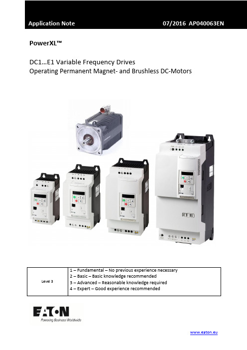
PowerXL™DC1…E1 Variable Frequency DrivesOperating Permanent Magnet- and Brushless DC-MotorsContents1 General (5)2 Selection of the Motor Control Mode (6)2.1 Motor Control Mode (P-60) (6)3 Setting Motor Data (7)3.1 Motor Nom Voltage (P-07) (7)3.2 Motor Nom Current (P-08) (7)3.3 I-CurrentLimit (P-63) (8)3.4 Motor Nom Frequency (P-09) (8)3.5 Motor Nom Speed (P-10) (8)3.6 Switching Frequency (P-17) (9)3.7 Motor Identification (P-61) (9)4 Optimization (11)4.1 Motor performance at low speed (11)4.2 Optimization of the speed controller (11)5 Faults and possible root causes (12)6 Example how to set motor parameters (13)Danger! - Dangerous electrical voltage!∙Disconnect the power supply of the device.∙Ensure that devices cannot be accidentally restarted.∙Verify isolation from the supply.∙Cover or enclose any adjacent live components.∙Follow the engineering instructions (AWA/IL) for the device concerned.∙Only suitably qualified personnel in accordance with EN 50110-1/-2 (VDE 0105 Part 100) may work on this device/system.∙Before installation and before touching the device ensure that you are free of electrostatic charge.∙The functional earth (FE, PES) must be connected to the protective earth (PE) or the potential equalization.The system installer is responsible for implementing this connection.∙Connecting cables and signal lines should be installed so that inductive or capacitive interference does not impair the automatic control functions.∙Suitable safety hardware and software measures should be implemented for the I/O interface so that an open circuit on the signal side does not result in undefined states.∙Deviations of the mains voltage from the rated value must not exceed the tolerance limits given in the specification, otherwise this may cause malfunction and/or dangerous operation.∙Emergency stop devices complying with IEC/EN 60204-1 must be effective in all operating modes. Unlatch-ing of the emergency-stop devices must not cause a restart.∙Devices that are designed for mounting in housings or control cabinets must only be operated and con-trolled after they have been properly installed and with the housing closed.∙Wherever faults may cause injury or material damage, external measures must be implemented to ensurea safe operating state in the event of a fault or malfunction (e.g. by means of separate limit switches, me-chanical interlocks etc.).∙Frequency inverters may have hot surfaces during and immediately after operation.∙Removal of the required covers, improper installation or incorrect operation of motor or frequency invert-er may destroy the device and may lead to serious injury or damage.∙The applicable national safety regulations and accident prevention recommendations must be applied to all work carried on live frequency inverters.∙The electrical installation must be carried out in accordance with the relevant electrical regulations (e. g.with regard to cable cross sections, fuses, PE).∙Transport, installation, commissioning and maintenance work must be carried out only by qualified per-sonnel (IEC 60364, HD 384 and national occupational safety regulations).∙Installations containing frequency inverters must be provided with additional monitoring and protective devices in accordance with the applicable safety regulations. Modifications to the frequency inverters us-ing the operating software are permitted.∙All covers and doors must be kept closed during operation.∙To reduce the hazards for people or equipment, the user must include in the machine design measures that restrict the consequences of a malfunction or failure of the frequency inverter (increased motor speed or sudden standstill of motor). These measures include: – Other independent devices for monitoring safety related variables (speed, travel, end positions etc.).•Electrical or non-electrical system-wide measures (electrical or mechanical interlocks).•Never touch live parts or cable connections of the frequency inverter after it has been discon-nected from the power supply. Due to the charge in the capacitors, these parts may still be aliveafter disconnection. Consider appropriate warning signs.DisclaimerThe information, recommendations, descriptions, and safety notations in this document are based on Eaton’s experience and judgment and may not cover all contingencies. If further information is required, an Eaton sales office should be consulted. Sale of the product shown in this literature is subject to the terms and conditions outlined in the applicable Terms and Conditions for Sale of Eaton or other contractual agreement between Eaton and the purchaser. THERE ARE NO UNDERSTAND-INGS, AGREEMENTS, WARRANTIES, EXPRESSED OR IMPLIED, INCLUDING WARRANTIES OF FITNESS FOR A PARTICULAR PURPOSE OR MERCHANTABILITY, OTHER THAN THOSE SPECIFICALLY SET OUT IN ANY EXISTING CONTRACT BETWEEN THE PARTIES. ANY SUCH CONTRACT STATES THE ENTIRE OBLI-GATION OF EATON. THE CONTENTS OF THIS DOCUMENT SHALL NOT BECOME PART OF OR MODIFY ANY CONTRACT BETWEEN THE PARTIES. As far as applicable mandatory law allows so, in no event will Eaton be responsible to the purchaser or user in contract, in tort (including negligence), strict liability, or otherwise for any special, indirect, incidental, or consequential damage or loss whatsoev-er, including but not limited to damage or loss of use of equipment, plant or power system, cost of capital, loss of power, additional expenses in the use of existing power facilities, or claims against the purchaser or user by its customers resulting from the use of the information, recommendations, and descriptions contained herein. The information contained in this manual is subject to change without notice.1GeneralDevices of the series PowerXL™ DC1…E1 are variable frequency drives for the supply of three phase motors. By default they are configured in a way, that induction motors of the respective power class can be supplied without changing the settings. The connection of permanent magnet motors (PM Motors) and Brushless DC Motors (BLDC Motors) is also possible, but requires the selection of the respective Motor Control Mode and an adaptation of some parameters.Devices of the series DC1…E1control PM motors and BLDC motors in …open loop“ without feedback by a speed sensor. Compared to induction motors they are mainly used because of the smaller frame size and an increased efficiency. The applications are similar to the ones with induction motors, but with increased dynamics. The series DC1…E1 is NOT intended to be used in servo applications with PM- and BLDC motors and therefore DC1…E1 doesn’t have functionalities like positioning …..In this Application Note the following aspects are covered:∙Selection of the motor control mode∙Adaptation to the connected motor∙Optimization of the application∙Trouble shooting∙Example: PM-Motor settingsSome required parameters are inside level 3. This level has to be activated by prompting the pass-word into P-14 (Password). The password is 201 by default.See also: AP040052EN “Access to Parameter Level 2 + 3 – Parameter lock –Load Default”.This Application Note presumes that the user is familiar with vector control of induction motors and the setting of the respective parameters, as well as with the optimization of speed control loops.2Selection of the Motor Control ModePM motors and BLDC motors require a different control algorithm compared to induction motors, for which the default settings are intended. A selection is done via parameter P-60.NOTE: The difference between PM motors and BLDC motors is mainly the wave form of the induced voltage (Back EMF). The control modes of DC1…E1 are optimized for that. On the market ther e is no clear differentiation between the two types of motors and sometimes one can find BLDC motors which are named as PM motors or PM motors with a similar induced voltage as a BLDC motor. In case of a bumpy run in the control mode for PM motors (P-60 = 2) sometimes an improvement can be achieved by selecting the control mode for BLDC motors (P-60 = 3).2.1Motor Control Mode (P-60)This parameter adapts the device to the type of the connected motor and determines the way of control. The information given in this Application Note are valid for PM motors and BLDC motors only and refer to the settings P-60 = 2 and 3.Information for the control of induction motors (P-60 = 0 and 1): see Application Note AP040049EN.3Setting Motor DataBefore switching on the motor, the motor data according the name plate or the data sheet have to be prompted and a motor identification run has to be performed.3.1Motor Nom Voltage (P-07)This parameter has to be set to the value of the induced voltage (back EMF) at rated speed. This volt-age is the voltage between two phases. In case the manufacturer states the value between phase and neutral, it has to be multiplied by √3.Inside the documentation of the motor manufacturers one can find the required information in dif-ferent formats.∙as a voltage value ( sometimes called “rated voltage”)∙as a voltage constant (induced voltage at a certain speed, mostly 1000 rpm). In this case the volt-age at the required speed has to be calculated.Example:∙voltage constant = 50 V / 1000 rpm∙required speed = 3000 rpmP-07=50 V1000 rpm∙ 3000 rpm= 150 VeNote: the voltage given by the motor manufacturers can have different meanings:∙The voltage induced at rated speed (Back-EMF). In this case this value has to be prompted.∙The voltage which is present at rated speed and rated torque. This value is higher than the in-duced voltage. It can possibly lead to a situation where the motor takes more current respec-tively runs bumpy. What are the possibilities to determine the right value?o Run motor at rated speed and switch off. Take an oscilloscope and measure the in-duced voltage directly after switch off.3.2Motor Nom Current (P-08)Rated current of the motor. By default, parameter P-08 …Motor Nom Current“ is set to the rated cu r-rent I e of the variable frequency drive. P-08 is also used to set the thermal protection for the motor. In case the rated current of the motor is different to the one of the variable frequency drive, P-08 has to be set accordingly to provide a thermal motor protection.e3.3I-CurrentLimit (P-63)The nominal current of the motor (P-08) can be exceeded for a certain time to provide additional torque during acceleration. In default it is 150 % of the rated current for 60 s within 10 minutes or the equivalent.The maximum value can be set with P-63. This setting has no influence on the motor protection and determines only the max. possible current.This function is of help in cases, where high inertias are accelerated. From experience this can some-times lead to trips because of overcurrent, in cases where the max. current and the hardware trip threshold of the device are too close.3.4Motor Nom Frequency (P-09)Frequency which is necessary for the required speed of the motor. Mostly it can be found as “rated frequency” on the motor name plate or in a data sheet. In case the frequency is not known, it can be calculated out of speed and number of poles p.P-09 [Hz]=n [rpm] ∙p2 ∙60 s/minNOTE: A change of P-09 affects the following parameter settings:3.5Motor Nom Speed (P-10)Motor rated speed in rpm. This is the speed at the frequency set with P-09.NOTE: A change of P-09 “Motor Nom Frequency” will set P-10 to 0!3.6 Switching Frequency (P-17)Switching frequency of the power section. With PM motors and BLDC motors a minimum switching frequency of 16 kHz is recommended. Setting the switching frequency is always a compromise be-tween a smooth run of the motor at higher values and resulting additional losses at the same time. At values above 16 kHz it has to be noted, that DC1…E1 possibly has to be derated and in some cases a device with the next higher rating has to be used.3.7 Motor Identification (P-61)A motor identification run MUST be performe d when using a device of the DC1…E1 series together with a PM motor or a BLDC motor (P-60 = 2 or 3). It sets the parameters automatically, which are necessaryfor an optimal performance. After the motor identification run the drive is ready to be used. Further optimization, see below.The motor identification run determines the values of the following parameters∙ Motor Stator Resistance (P-64)∙ Motor Stator Inductance d-axis (P-65) ∙ Motor Stator Inductance q-axis (P-66)The respective values can also be prompted manually, in case they are available from the motor manufacturer. It is recommended to rely on the motor identification run, because it gives very accu-rate values and ensures optimal performance.A motor identification run is performed during stand still. The internal motor model uses the results for an optimal control of the connected motor.Procedure:∙ Real Time Edit Mode of a DrivesConnect Software, which is possibly connected to the drive, hasto be deactivated. Better: Unplug the connection at the RJ45 jack when performing a motor iden-tification run.∙ DC1…E1 must not be enabled (no START signal) ∙ Select parameter P-62 ∙ Press OK∙ is displayed ∙ Change value to∙ Acknowledge with OK The identification starts automatically, display: resp. Auto-tuning (OLED-display)∙ After the identification the value will automatically be reset to zero. Display: ∙ The device has determined the required parameters.HINT: The motor identification run has ALWAYS to be performed at the device itself. It is NOT possi-ble to activate it through the parameter software DrivesConnect. The motor parameters P-07, P-08and P-09 have to be set before starting the motor identification.4 Optimization4.1 Motor performance at low speedNormally PM motors and BLDC motors can be used in a speed range of 20:1. The series DC1…E1 has a boost function, which increases the torque in the lower range resulting in an improved start behavior and true running in the lower speed range.In case …Motor Control Mode“ P -60 = 2 (PM motors) or P-60 = 3 (BLDC motors), a current, which is injected into the motor, can be set with P-11. The amount of current is calculated as follows:I Boost = 4 ∙ P-11 ∙ P -084.2 Optimization of the speed controllerThe control of PM motors and BLDC motors is based on vector algorithms and the speed loop can be optimized. The factory settings are intended for induction motors. PM motors and BLDC motors al-low higher gains and therefore shorter response times and improved behavior.Parameter P-62 …MSC Gain“ affects the proportional gainof the speed controller as well as the inte-gral one. Changes should be done step by step, while observing their impact to the system behavior. Increasing the value leads to a stronger reaction and consequently to a reduction of the response time. Too high values of P-62 can lead to an instability of the system.5Faults and possible root causesGeneral fault messages and their root causes are described in the user manual for the drives series DC1…E1. The faults listed below are especially related to the use of PM motors and BLDC motors.6Example how to set motor parametersExcerpt from a data sheet of a PM motor manufacturer:Settings of motor parameters:∙P-07 = KE ∙ n N = 64,2 V / 1000 rpm ∙ 3600 r/min = 231 V*∙P-08 = 7.5 A∙P-09 = 240 Hz∙P-10 = 3600 r/minFurther important settings∙Enable menu level 3 (Prompt value defined by P-37 + 100 into P-14. Default: 201)∙The switching frequency (P-17) has to be at least 16 kHz∙Select motor control mode with P-60 (in this example: 2 PM motor with speed regulation) ∙Perform motor identification run with P-61∙Optimize motor performance at start and low speeds (P-11).∙Optimize speed controller, if necessary。
282manual introl design inc DC driver 90V直流电机驱动说明书

Introl Model 282Regenerative Controller Operation ManualIntrol Design, Inc.48 North StreetLockport NY, 14094ImportantThis control has been designed as a component intended to be implemented in a control system. Introl Design, Inc. has no control over the numerous control schemes, therefore it is the responsibility of the user to install this device in a system with the safeguards in place to prevent personal injury or equipment damage. The user should comply with the National Electrical Code as well as any local or other applicable codes. Although every effort has been made to assure the accuracy of the information contained in this manual, Introl Design, Inc. accepts no liability whatsoever with respect to the information provided herein. There are no implied warranties of merchantability or fitness for a particular purpose that apply to the control described in this manual.SPECIFICATIONS - 282 REGENERATIVE FULL WAVE SCR 4-QUADRANT DRIVEInput power - 115 VAC 1/50-60 Hz 1/8 - 1 HP230 VAC 1/50-60 Hz 1/4 - 2 HPDrive S.F. (max. ratings) 1.0IR Comp. Adjustment StandardMax. Speed Adjustment (% of rated speed) 70 - 115Current Limit (% of Max. rating) F.L., Adjustable to 150%Accel. Adjustable 0.1 to 10 Sec.Speed RegulationArm. Volt feedback 95% load change 2-5% of Top SpeedTach. Feedback 1.0 of Top SpeedOperator functionsPower, On/Off, Run/Stop andSpeed Adjustment and Customer suppliedForward and Reverse on chassis modelOperating ConditionsAltitude w/o derating 3300' above sea levelAmbient Temperature 0-55 degrees CChassis Mount Space Req. for TENV Enc. 1000 Cu. in./HPLine Voltage Variation 15%Line Frequency 50-60 HzOverload Cap. (as a % of max. rating) 150%/l min.Reference Power Supply ± 15 VDCSAFETY WARNINGImproper installation or operation of this drive may cause injury to personnel or failure.READ OPERATION INSTRUCTIONSDrive must be installed and grounded per local and national electrical codes. To reduce potential of electric shock, disconnect all power sources before initiating any maintenance of repairs. Keep hands and foreign objects away from ventilation and other openings. Keep air passages clear.INSTALLATIONAs with all electronic equipment, the enclosure should not be mounted in direct sunlight or exposed to other high level heat radiation from a furnace or other source. If it is necessary to mount the controller near such a heat source, a shield may be used to deflect the heat. It is essential that air movement around the controller be unrestricted and nothing should be left lying on the controller as this would interfere with heat transfer to the air.THE NATIONAL ELECTRIC CODE REQUIRES A SEPARATE FUSED DISCONNECTOR CIRCUIT BREAKER BE INSTALLED IN THE INCOMING AC POWER LINE TOTHE CONTROLLER. (See Controller Rating Table)The table gives AC line voltages, line amperes, DC armature output amps, and maximum field output amps for various motor HP ratings. The AC line amperes (RMS) should be used in sizing the wire forboth the armature output and the AC line input connections. The field current is less than (1) one ampere for each of the motors listed and wire for field connections can be sized accordingly. GROUNDINGIt is imperative that the controller frame be connected to building ground for the safety of the operating personnel.WARNINGAC POWER MUST BE DISCONNECTED FROM THE DRIVE CABINET TO ELIMINATE THE HAZARD OF ELECTRICAL SHOCK BEFORE IT IS SAFE TO TOUCH ANY OF THE INTERNAL PARTS OF THE DRIVE. CIRCUITS MAY BE AT LINE POTENTIAL WHETHER THE ENCLOSED DRIVE IS OPEN OR CLOSED. USE EXTREME CAUTION.The controller has been thoroughly tested at the factory to insure proper operation when installed in accordance with the following installation instructions and diagrams.INSERT - WARNINGThe Model 282 is a non-isolated drive. In other words, the common of the controller (pin 4 of TB1) is connected to the power section. (See Fig.) If the common of the controller is connected to earth ground without an isolation transformer, there will be a direct short circuit from the line to earth ground, resulting in damage to the controller. If the common must be connected to earth ground, an isolation transformer is required. (The secondary of the transformer must not be referenced to earth ground.) Also, the common of one controller should not be connected to the common of other controllers unless each one has an isolation transformer. If isolation is required, Introl can provide an isolation board (part number 241-22CH) to be mounted on the Model 282.SET-UP PROCEDURESELECT MODE OF CONTROLa. Speed - If potentiometer is to control speed, jumper 3 to Pin 9 on TB1 or connect tachometerfeedback to Pin 4 & 9. (Diag. 282)b. Torque - If potentiometer is to control torque, connect jumper from "A" to "D" on the top PCboard and disconnect jumper 3 from 9 on TB1.DETERMINE OPERATING VOLTAGEa. For 115 VAC input and 0-90 VDC output, place jumper on transformer "A" to "D" and "B" to"E".b. For 230 VAC input and 0-180 VDC output, place jumper on transformer "A" to "C" and "B" to"C". Select Current Limit Level.SELECT CURRENT LIMIT LEVELa. Refer to the motor nameplate for DC Armature volts and HP rating. Monitor current limitpotentiometer for maximum 150% F.L. motor current. Full counter-clockwise equalsapproximately 17 amps, and full clockwise equals 3 amps.Install any applicable kits as detailed in kit instructions. Control may now be mounted in itsdesignated area. On chassis mounted units, connect operating devices as shown oninterconnection diagrams at back of manual.CHECK MOTOR AND MOTOR NAMEPLATEa. If motor has a thermal overload, connect as shown on interconnection diagrams at back of thismanual. NOTE - Motor thermal connections are often labeled P1 and P2.b. It the motor has a field winding, connect as shown on interconnect diagrams to control fieldterminals. (With a 115 AC supply, the field output will be fixed at 100 VDC; at 230 VAC thefield output will be 200 VDC.) Some motors have dual fields 150-100 VDC and 100/200 VDC.) Care should be taken to insure the correct voltage is connected.c. If the motor has a permanent magnet field, no field connections need be made. INSTALLATION CHECKSPrior to making the AC input line connections, follow these checks using a volt-ohm-meter. WARNING - Do not use a vacuum tube voltmeter or other similar type of meter that has to be powered with AC power.NOTE - With the red as the positive lead, make the following check:Red + Black - Range of Acceptable ReadingsA2 Al 1-4 OhmsF2 F1 100-700 OhmsFl, F2, Al, A2 GND InfiniteIf any of the checks are not within the indicated range, verify all connections and then recheck.Use of an isolation transformer to reduce the possibilities of ground paths is a recommended safety practice. Pin 4 of TB1 can then be connected to earth ground. (ONLY WITH ISOLATION TRANSFORMER)DISCONNECTING MEANSA fused AC line disconnect or circuit breaker is required by the National Electrical Code (NEC). This AC line disconnect or circuit breaker must be installed ahead of the controller.Transformer ProgrammingFor 115 VAC operation -Jumper A-D, B-EFor 230 VAC operation -Jumper A-C, B-CTorque or Current Mode -When operating in the torque mode the current range from 0 to 100% can be selected by adjustment of the speed/torque pot.OPERATION INSTRUCTIONSMAXIMUM SPEED ADJUSTMENTa. Connect motor to the load and allow at least 15 min. warm up before adjusting.b. With the drive running, set the operator's SPEED POT FOR MAXIMUM SPEED POSITION.c. Maximum speed has been preset. Should you wish to raise or lower this setting, adjust theSPEED pot on the printed circuit board. Maximum speed may be increased to approximately15% over motor nameplate base speed of reduced to approximately 70% of motor nameplatebase speed. DO NOT EXCEED MOTOR NAMEPLATE MAXIMUM SPEED RATING.d. Using a hand held tachometer or by visually observing the machine operation, adjust control tothe desired maximum setting.I. R. COMP. ADJUSTMENTThis adjustment is provided to overcome the motor's natural tendency to slow down with increasing load. If improved speed or load characteristics are required by the application, the I.R. Comp. pot can be advanced clockwise to reduce the motor's tendency to slow down. NOTE - If this control is advancedtoo far, the motor speed will tend to oscillate or hunt. If this condition occurs, re-adjust the I.R. Comp adjustment counter-clockwise until motor speed stabilizes without oscillating.SPEED ADJUSTMENTSa. S ee enclosed schematic for different reference pot hook-up configurations.b. Regenerative braking - Lowering the speed reference pot to a lower set-ting will result in brakingaction. This will depend on the setting of the accel/decel pot.c. S topping - Disconnect the reference voltage input from the control. The motor will brake to astop.d. Reversing – Contactorless reversing is accomplished by simply reversing the reference polarity. ACCEL/DECELThe Accel/Decel pot controls both the accel and decel ramp and can be adjusted between 0.1 and 10 sec. on the standard control. Longer rates can be obtained for special applications.CURRENT MODEDisconnect the external tachometer or remove jumper 3 to 9 and add jumper D to B on the PC board. With max. reference applied that will be used, adjust the SPEED/TORQUE pot from max. c.w. to c.c.w. until max. motor current is obtained. Then retard the external reference source to lower current if desired. A transducer signal may be utilized instead of a pot reference voltage.TROUBLESHOOTINGCONTROL BLOWS LINE FUSESa. Shorted Power moduleb. Shorted field supplyc. Defective motord. Shorted suppressore. Short to groundCONTROL WILL NOT STARTa. No incoming powerb. Blown fusec. Defective Power moduled. Defective component on control boarde. Defective relayMOTOR WILL NOT COME UP TO SPEEDa. Speed pot set too lowb. Motor overloadedc. Current limit set too lowd. Defective power module (unit may be operating half-wave)e. Feedback in wrong positionf. Control malfunctionMOTOR WILL NOT STOPa. No feedback voltageb. Defective Speed adjust pot (external)c. Defective component on control boardd. Defective power modulee. Ramp stop mode being used & IR comp pot too highf. Tach (if used) disconnectedMOTOR IS UNSTABLE OR PULSATESa. IR Comp. pot set too highb. Motor is overhaulingc. Defective motord. Defective component on control boarde. Cyclic type loadMOTOR WILL NOT MAINTAIN SPEED UNDER LOADa. IR Comp. pot set too lowb. Motor overloadedc. Defective component on control boardd. Current limit too lowMODEL 282C SERIESMounting DimensionsW ARRANTY P OLICYIntrol Design, Inc. guarantees its products against defects in workmanship and materials for a period of twelve (12) months from date of purchase, not to exceed twenty-four (24) months from date of manufacture. Final determination of whether a device is defective rests with Introl Design. Introl Design must be notified about any alleged defects, and will provide the customer with shipping instructions. If inspection reveals defects caused by faulty materials or workmanship, Introl reserves the right either to rebuild the device using new or refurbished and warranted parts or to replace the device with a new device, returning to the buyer a device meeting full factory standards for new performance. Any repairs necessary due to customer modification will be considered non-warranty and billed by the factory at current rates. Buyer will bear costs of transportation to and from the factory, risk of loss for goods not at the factory, and costs required to remove or prepare for shipment and to reinstall equipment after repair. Introl Design, Inc. assumes no responsibility for injuries or damages to persons or property arising out of improper use of this device, and Introl Design's liability arising out of the device or its use, whether on warranty or otherwise, shall not exceed the cost of correcting defects. There are no expressed or implied warranties of merchantability or fitness for a particular purpose that apply to this device. Introl Design, Inc. reserves the right to make changes or improvements in its products without incurring any obligation to make such changes or improvements in the similar products previously purchased.Introl Design, Inc.48 North StreetLockport, NY 14094Phone (716) 434-6919Fax (716) 434-1911introl@。
- 1、下载文档前请自行甄别文档内容的完整性,平台不提供额外的编辑、内容补充、找答案等附加服务。
- 2、"仅部分预览"的文档,不可在线预览部分如存在完整性等问题,可反馈申请退款(可完整预览的文档不适用该条件!)。
- 3、如文档侵犯您的权益,请联系客服反馈,我们会尽快为您处理(人工客服工作时间:9:00-18:30)。
DC系列直流串励电机
使用维护说明书
一、电机适用于蓄电池供电的各种电动车辆,如电动车、叉车、搬运车、堆垛车、电动摩托等作行走用
的电动机。
1、适用环境:
a: 海拔不超过1200M。
b: 环境温度≯40°C,最低≮-25°C。
c: 相对湿度直到100%,在电机表面形成凝露。
2、以满足车辆重载起动,满载爬坡及平路高速运行等多种工况,而不需借助机械变速来实现。
二、电机结构
1、电机为串励直流电动机,主要由定子、转子、刷盖和驱动盖等组成。
2、电机分为全封闭式和开启式等。
全封闭可防止异物、灰尘和水等物质进入,开启式可以更方便
维护换向器及电刷更换。
3、电枢的导线及换向器均采用TIG焊接,联接可靠,可适用各种严酷的工作环境。
4、具体外形及技术参数参照外形图或订货单要求
三、电机接线(串励):
四、电机使用维护:
1、用户须按照说明书要求,才能保证电动机正常运行。
2、电机应保存在通风、干燥、清洁的地方,如保存时间过长(半年),须检查电机的润滑脂,及
其冷态绝缘电阻,其阻值不小于0.5MΩ,如果达不到要求,须烘干,置于烘箱内温度为80°C
±10°C。
3、装机前,检查确认电机轴伸端是否有轴承(可手工轻晃轴伸,轴伸有偏摆的,是无轴承),电
机轴伸端无轴承的,需保证电机轴线与电机端盖外止口(或机座止口)同轴度不大于0.1mm。
装机后检查电枢是否旋转灵活,无擦碰现象。
4、检查电机连接线是否可靠。
5、检查换向器表面有无污物,电刷在刷盒内滑动自如。
6、本电机(串励)不准在空载状态下通电运转。
如用户必须空载运转时,接线端的电压必须控制
在小于15%的额定电压。
7、冷却空气不应有腐蚀性气体。
8、
部件名称绝缘等级测量方法允许温升
电枢绕组
F/B 电阻法100/80
定子绕组电阻法100/80 换向器点温计法90/80
9、定期检查,电机内部零件是否变形,换向器表面状况及电刷磨损情况,发现异常,应及时进行
维护保养后,方可恢复工作。
每半年(电动车运行工况频繁、复杂的,检查周期相应缩短)至
少按下列方法检查一次:
a: 清除电机污垢、积灰、积炭,以保证电机正常工作。
b: 清洗或更换轴承,清洗后滚道内加注3#锂基润滑脂。
c: 根据电刷磨损情况,及时到专业维护单位更换新换碳刷后,须保证其磨合孤面不小于70%,方可投入运行。
10、电机允许短时过载的最大容许电流为额定值3倍。
此时过截转矩为额定转矩的4.5倍,时间不
得超过1分钟。
11、本电机为1小时工作制,不允许超时工作。
12、有计划检修工作不应太少,至少一年一次。
13、随机文件:合格证:一份
产品说明书:一份
14、其他配件可根据用户要求,在合同中增订另行计价:
如:备用电刷,电机引线,电控等
五、型号说明:
DC48-4-15A2
DC:直流串励电动机
48:额定电压48V
4:额定功率4KW
15:额定转速1500RPM
A2:安装方式—底脚或者方法兰A1:底脚安装A3:方法兰安装A5:圆法兰安装
六、保修期
电机整机保修壹年(不含电刷)。
客户应严格按照第四项要求使用维护电机,因用户使用不当造成的电机故障,不在保修范围之内,保修期内,电机出现异常,应及时与厂家联系,若客户自行处理,厂家概不负责。