虚拟卡口安装说明书(1)
智能非接触读卡器安装说明书
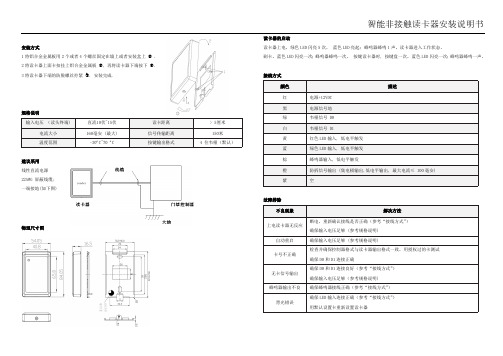
智能非接触读卡器安装说明书安装方式1将铝合金金属板用2个或者4个螺丝固定在墙上或者安装盒上 .2将读卡器上面卡扣挂上铝合金金属板 , 再将读卡器下端按下 ●. 3将读卡器下端的防脱螺丝拧紧 ❍. 安装完成.规格说明建议采用线性直流电源22AWG 屏蔽线缆; 一端接地(如下图)物理尺寸图读卡器的启动读卡器上电,绿色LED 闪亮5次, 蓝色LED 亮起;蜂鸣器蜂鸣1声,读卡器进入工作状态。
刷卡,蓝色LED 闪亮一次;蜂鸣器蜂鸣一次。
按键读卡器时, 按键盘一次,蓝色LED 闪亮一次;蜂鸣器蜂鸣一声。
接线方式故障排除Keypad & Proximity Flash Mount Reader Installation ManualMounting:1.Install the metal plate on the wall with two or four screws, which dependson different kinds of gang box being installed .2.The cover shall clip on the upper edge the push in the bottom part asshow in diagram●.3.Tighten the secure non-dropout screw, which located underneath of thereader to fix the reader and the back plate❍, installation is completed.Recommendation:1.Linear DC Power Supply;2. 22AWG shielded cable; it’s required to do “one-point” ground. (As shown in the diagram)Power up Sequences:1.When reader is powered up, the Green back will flicker for 5 seconds. The reader will beep once and thereader is in Ready mode.2.Present the card. The Blue LED will flicker once; buzzer will beep once.3.When card is present and read by the reader, blue back lit will flash once; and buzzer will beep once aswell. The card data will then transmit to the controller. After, weather the back lit of the reader will remain ON or Flash or change to Green or Red color, this shall depend on the Green and Red LED inputs Wiring:Troubleshooting:。
海康(卡口)摄像机安装步骤.

杆高6米 立杆基础
安装抓拍单元
抓拍单元安装于立杆挑臂上,抓拍单元的安装分为三个组件安 装。分别是防护罩、万向节、抱箍。其中防护罩安装主要是遮 阳罩与防护罩主体的安装,抱箍用于固定安装位置,万向节用 于连接防护罩和抱箍。 遮阳罩安装说明及示意图 从抓拍单元配件包中找出螺钉、垫柱、四氟垫、垫圈等; 将垫柱固定在护罩上盖上; 将遮阳罩孔对准垫柱中心孔,用螺钉将遮阳罩固定牢固,安装 示意图如下(左)所示,安装好后效果图如下(右)所示。
安装抓拍单元
万向节安装说明
首先将防护罩与万向节连接好,如图所示,防护罩底部有2个
螺孔:
相机
万向节
抱箍
抱箍
万向节分为上下两面,其中上面为与防护罩对应的两个螺孔, 其下面为与抱箍连接的螺丝槽。
固定万向节细节注意点
安装抓拍单元
抓拍机接线端子
抓拍机接线端子实图
抓拍单元接线
补光灯接线
安装注意
1:抓拍单元300万抓拍两个车道,应安装在两个车道的中 间线正上方。 2:抓拍单元600万抓拍三个车道,应安装在三个车道的中 间车道正上方。 3:按设备布局图要求的与抓拍单元的间距安装补光灯。 补光灯的安装位置,例如卡口,每个车道的补光灯距离对应 的抓拍摄像机5米。 卡口抓拍单元型号: 300万 :VCU-7023-T (标配25mm) 600万:VCU-902C-ITK (标配30mm) 闪光灯:SL- 1211 注意:高清频闪补光灯角度调整好之后务必固定好抱箍和 补光灯之间的螺母以防止补光灯的角度发生变化。
车道6 车道5 车道4
闪光灯1 抓拍单元1
手井
落地机柜
闪光灯2 闪光灯3
手井
立杆基础
屏蔽双绞线(RVVSP2*1.0) 室外屏蔽超5类网线(STP CAT-5E) 电源线(RVV3*1.5)
AY-x5B 系列 MIFARE Classic EV1 CSN 读卡器安装手册说明书

AY-x5B SeriesMIFARE Classic® EV1 CSN ReadersInstallation Manual 11. IntroductionThe AY-x5B is a series of RFID proximity card readers to be installed for use with access control systems.The AY-x5B series reads the card serial number (CSN) from MIFARE Classic® EV1 credentials (4 UID and 7 UID) and transmits its data to the access control system using Wiegand 26-Bit output.Other Wiegand formats and the Clock & Data format are available as factory configurable options.Figure 1: AY-x5B SeriesAY-M5BAY-H5BAY-L5BAY-K5B2. Technical Specifications2.1Electrical Characteristics* Measured using a Rosslare MIFARE Classic EV1 card or equivalent. Range also depends on installation environment, reader voltage, and proximity to metal.2.2 Environmental Characteristics2.3 Physical Characteristics3. InstallationInstallation of an RFID reader adjacent to metallic surfaces might alter the reader’s specifications. To diminish thisinterference, use a plastic spacer when mounting the reader. 3.1Installation KitThe installation kit consists of the following items to be used duringthe installation procedure:Two pan head mounting screws and screw anchors3.2 MountingBefore mounting, you should determine the best location for the reader.To mount the reader:1. Drill two holes for mounting the reader on the wall.2. Insert a screw anchor into each hole.3. Drill a 10-mm (7/16”) hole for the cable. If mounting on metal,place a grommet or electrical tape around the edge of the hole. 4. Remove the screw from the bottom of the unit. 5. Remove the reader's snap-off front cover.6. Insert the unit’s cable wire into the cable hole and wire the unit asdescribed in Section 3.3. A linear type power supply is recommended. 7. Align the two holes of the reader with those drilled in the wall andfirmly attach the reader to the wall with two screws (Figure 2).Figure 2: Inserting Mounting Screws (similar for all models)8. Relocate the front cover onto the reader.9. Secure the front cover with the screw at the bottom of the unit.20706-0960191+003.3 WiringThe AY-x2B is supplied with 5 color-coded wires 25 cm (10 in.) in length.To connect the reader to the controller:1. Select the appropriate connections according to Table 1.Table 1: Wiring2. Connect the wires to the corresponding controller wires and covereach joint with insulating tape. 3. Trim and cover all unused conductors.When using a separate power supply for the reader, this supply and that of the controller must have a common ground3.4 Operation InstructionsOnce the reader is wired to a power supply and to the controller, you should test the reader.To test the reader: 1. Power up the reader.Upon power up, the reader flashes and beeps once during Self-Test. The LED then turns red indicating the readers has entered Standby mode.2. Apply a MIFARE Classic EV1 credential to the reader.The reader flashes and beeps once indicating the card has been read successfully.Declaration of ConformityFCC ID:GCD-AYX25B ▪This device complies with Part 15 of the FCC Rules. Operation issubject to the following two conditions: ▪ This device may not cause harmful interference.▪ This device must accept any interference received, including interference that may cause undesired operation.▪Changes or modifications not expressly approved by the party responsible for compliance could void the user's authority to operate the equipment.This equipment has been tested and found to comply with the limits for a Class B digital device, pursuant to part 15 of the FCC Rules. These limits are designed to provide reasonable protection against harmful interference in a residential installation.This equipment generates, uses, and can radiate radio frequency energy and, if not installed and used in accordance with theinstructions, may cause harmful interference to radio communications. However, there is no guarantee that interference will not occur in a particular installation. If this equipment does cause harmfulinterference to radio or television reception, which can be determined by turning the equipment off and on, the user is encouraged to try to correct the interference by one or more of the following measures: ▪ Reorient or relocate the receiving antenna.▪ Increase the separation between the equipment and receiver. ▪ Connect the equipment into an outlet on a circuit different from that to which the receiver is connected.▪Consult the dealer or an experienced radio/TV technician for help.Limited WarrantyThe full ROSSLARE Limited Warranty Statement is available in the Quick Links section on the ROSSLARE website at . Rosslare considers any use of this product as agreement to the Warranty Terms even if you do not review them.Contact InformationUnited States and CanadaRosslare Security Products, Inc. Southlake, TX, USAToll Free: +1-866-632-1101 Local: +1-817-305-0006 Fax: +1-817-305-0069 *******************************EuropeRosslare Israel Ltd.22 Ha'Melacha St., P.O.B. 11407 Rosh HaAyin, IsraelTel: +972-3-938-6838 Fax: +972-3-938-6830*******************************Latin AmericaRosslare Latin AmericaBuenos Aires, ArgentinaTel: +54-11-4001-3104*******************************ChinaRosslare Electronics (Shenzhen) Ltd. Shenzhen, ChinaTel: +86-755-8610-6842 Fax: +86-755-8610-6101*******************************Asia Pacific, Middle East, AfricaRosslare Enterprises Ltd. Kowloon Bay, Hong Kong Tel: +852-2795-5630 Fax: +852-2795-1508*********************************IndiaRosslare Electronics India Pvt Ltd. Tel/Fax: +91-20-40147830 Mobile: +91-9975768824 *****************************CERTISO 9001ISO 14001。
FLA 3301 串口扩展卡安装指南说明书

FLA3301-Serial Ports Extension CardINSTALLATION GUIDEIG-0016-001.4en-US ENGLISHImportant User InformationDisclaimerThe information in this document is for informational purposes only.Please inform HMS Industrial Networks of any inaccuracies or omissions found in this document.HMS Industrial Networks disclaims any responsibility or liability for any errors that may appear in this document.HMS Industrial Networks reserves the right to modify its products in line with its policy of continuous product development.The information in this document shall therefore not be construed as a commitment on the part of HMS Industrial Networks and is subject to change without notice.HMS Industrial Networks makes no commitment to update or keep current the information in this document.The data,examples and illustrations found in this document are included for illustrative purposes and are only intended to help improve understanding of the functionality and handling of the product.In view of the wide range of possible applications of the product,and because of the many variables and requirements associated with any particular implementation,HMS Industrial Networks cannot assume responsibility or liability for actual use based on the data,examples or illustrations included in this document nor for any damages incurred during installation of the product.Those responsible for the use of the product must acquire sufficient knowledge in order to ensure that the product is used correctly in their specific application and that the application meets all performance and safety requirements including any applicable laws,regulations,codes and standards.Further,HMS Industrial Networks will under no circumstances assume liability or responsibility for any problems that may arise as a result from the use of undocumented features or functional side effects found outside the documented scope of the product.The effects caused by any direct or indirect use of such aspects of the product are undefined and may include patibility issues and stability issues.Table of Contents Page1Preface (3)1.1About this Document (3)1.2Document History (3)1.3Related Documents (3)1.4Trademark Information (3)2Product Summary (4)3Safety,Environmental&Regulatory Information (5)3.1Scope (5)3.2ESD Damage Prevention (5)3.3Applicable Directives,Standards and Compliances (5)4Hardware Description (7)4.1Mechanical Layout and Interfaces (7)4.2Extension Card Label (7)4.3Dip Switch Configuration of Port S1 (9)4.4Front Panel LEDs (10)4.5Ewon Flexy Extension Cards Environmental Conditions (10)4.6Serial Port Specifications (10)4.7Plug the FLA3301into the Base Unit (11)4.8Firmware Port Naming Convention (15)5Power Requirements (17)6Powering On the Base Unit with its Extension Cards (18)7Check Card Detection on the Embedded Web Page (19)7.1Connecting to the Embedded Web Server (19)7.2Detected Cards Displayed in the System Page (19)This page intentionally left blankPreface 3(22)1Preface1.1About this DocumentThis document describes the hardware of the FLA 3301-Serial Ports Extension Card which belongs to the Ewon Flexy familyThe Ewon Flexy family is a range of modular industrial gateway/router and as its name Ewon Flexy suggests,it has been designed to enable numerous different combinations of base units with extension cards.For additional related documentation and file downloads,please visit /support .1.2Document History1.3Related Documents1.4Trademark InformationEwon ®is a registered trademark of HMS Industrial Networks SA.All other trademarks mentioned in this document are the property of their respective holders.Product Summary4(22)2Product SummaryThe present Installation Guide is focusing on the FLA3301-Serial Ports Extension Card which,assuch,needs to be inserted in one of the Flexy base units to work.The base units have their own Installation Guide which can be found in the Related Documents.This guide also addresses shortly how the extension cards integrate the base units as well assome recommendations on how to mount them.See Plug the FLA3301into the Base Unit,p.113Safety,Environmental&Regulatory Information3.1ScopeThe present heading addresses Safety,Environmental&Regulatory Information about the FLA3301-Serial Ports Extension Card.This extension card is belonging to the same compliance frame than the base units.In thepresent case of a telecommunication extension card,additional directives,standards andinstructions apply.3.2ESD Damage PreventionThe extension card described in this document is a module exposing both sides of an electronicprinted circuit board.Therefore,it is packed in an antistatic ESD bag.In order to avoid ESDdamage,the product must be handled with the necessary precaution including:•Grounded ESD protective work surface•Personnel grounding3.3Applicable Directives,Standards and CompliancesTheFLA3301inserted in a base unit belongs to class A Information Technology Equipment(ITE).In a domestic environment,this product may cause radio interference in which case the usermay be required to take appropriate measures.3.3.1Applicable European DirectivesThe FLA3301is in conformity with the following EC directives:•RoHS Directive2011/65/EU•RE Directive2014/53/EU3.3.2Applicable Safety StandardsThe FLA3301is in conformity with the following safety standards:•IEC/EN60950-1•UL60950-1•CSA-C22.2No60950-1-07•EN IEC 62368-1:2020 + A11:2020•UL 62368-1 Third Edition, revised October 22, 2021•CAN/CSA C22.2 No. 62368-1: 19 Third Edition, revised October 22, 20213.3.3FCC ComplianceThe FLA3301complies with Part15of the FCC Rules.Operating is subject to the following twoconditions:•This product may not cause harmful interference•This product must accept any interference received,including interference that may cause undesired operation.3.3.4CertificationsThe FLA3301has been certified by authorized bodies:•UL Certificate of Compliance(COC)#E350576-20230306•CB certificate# DK-133387-ULThese certificates can be downloaded as PDF files on the Ewon support web site:/support4Hardware Description4.1Mechanical Layout and InterfacesFig.1Mechanical layout and interfaces4.2Extension Card Label4.2.1Label Location and Included InformationThe identification label of the extension cards is placed on the solder side of the PCB.The different parts of the label are described below:Fig.2FLA 3301label4.2.2Part Number Structure for Extension Cards4.3Dip Switch Configuration of Port S14.4Front Panel LEDsFig.3Front panel LEDs4.5Ewon Flexy Extension Cards Environmental Conditions4.6Serial Port Specifications4.6.1Configurable Port S1Port S1is configurable by dip switch in 3different physical modes RS232,RS422and RS485,see Dip Switch Configuration of Port S1,p.94.6.2RS232Port S2Port S2is RS232only.4.7Plug the FLA3301into the Base Unit4.7.1Base Unit Slot CompatibilityThe FLA3301must be inserted in one of the“A”slots of the base unit.The reference code of the extension cards includes a letter defining their compatibility:•FL A xxxx:designate cards that fit into“A”slots.In addition to the card reference,each type of extension card bears a visual compatibility symbolon its front panel:Ewon Flexy205As the Flexy205has room for2slots,the type slot compatibility rule doesn’t apply.The FLA3301can be inserted in both slots.Fig.4Position of the“A”Slots on a Flexy205.Ewon Flexy10x&20xThe FLA3301must be inserted in the“A”slots which are the two slots on the far left of the Flexy 10x&20x.Fig.5Position of the“A”Slots on a Flexy10x&20x.4.7.2How to Insert into the Flexy Base UnitWait30seconds after turning off the equipment before inserting(or removing)an extensioncard to avoid possible damage to the base unit and the extension cards.Remove the slot filler of the location the new card will be inserted.To do so,press on both endsof the cover,note that the hooks are off-centered.Fig.6Remove the slot fillersInsert the extension card carefully and slide it down until the hook clicks.Make sure the card iscompletely inserted.DO NOT insist if a resistance is felt when trying to insert the card.This can occur if the extensioncard is inserted in a wrong slot type.In such case,check slot compatibility of the relevantextension card.Boot the unit for the inserted extension cards to be detected.The web interface of the Flexybase unit has a diagnostic page showing the extension cards in their order of detection(from leftto right).4.7.3Insertion of Multiple FLA3301Detection OrderThe boot sequence of the base unit includes an automated detection of the inserted extensioncards.This detection is done sequentially,slot per slot starting from left to right(when holdingthe base unit with its logo on the right side).Software CompatibilityThe base unit allows the insertion of multiple extension cards,sometimes of the same type.Some configurations including multiple extension cards,even if mechanically acceptable,are notsupported by the embedded software.Cards in excess are ignored during the automateddetection process which means that the base unit and its running extension cards will operatenormally.The Flexy firmware currently supports up to2FLA3301.The ignored card(s)will appear in the Diagnostic>Status>System Info>System but they willnot be functional.Fig.7Order of the Extension CardsThe picture above shows an example of a configuration that would be OK mechanically andpower wise but would not be supported by the firmware.During the boot process,the first2serial port extension cards are detected and both can be used.In case of2single Ethernet cards,these2cards are also detected but the second Ethernet card isnot supported by the firmware and cannot be used.The presence of this“ignored”card in thebase unit does not alter the operation of the base unit itself nor does it alter its“accepted”extension cards.4.8Firmware Port Naming ConventionDepending on the Base Unit and applying the left to right detection order of the extension cards,following port naming(COM1,COM2,...)will be applied inside the Ewon firmware.A)Base Units:Ethernet Switch and MPI&Ethernet(Flexy101,Flexy201,Flexy103,Flexy203)B)Base Units:Serial&Ethernet(Flexy102,Flexy202)Power Requirements17(22) 5Power RequirementsThe internal power converter of the Flexy base units has been dimensioned to cover a broadrange of different combinations of extension ers should make sure the total powerdemand of the extension cards does not exceed the capabilities of the base unit.That is why thenotion of“Energy Points”has been introduced.The Installation Guide“eWON Flexy-Base Units”includes a section giving the Available EnergyPoints of each type of base unit.The power requirements of each extension card is expressed in Energy Demand Points.Thisnumber is meant to check whether the balance with the Available Energy Points of a given baseunit with extension cards is OK or not.The Energy Demand Points of the FLA3301is1The Installation Guide of the“eWON Flexy-Base Units”also includes examples of practicalpower balance calculations.Powering On the Base Unit with its Extension Cards18(22)6Powering On the Base Unit with its Extension Cards When the Base Unit is powered on,it takes approximately25seconds for the unit to go throughits self-test procedure.The slots in which the extension cards have been inserted and their typeare detected during this process.If the boot process completes normally,you should observe the following LED status•Base Unit USR flashing green slowly•Extension Card232ON(Green if S1is configured in RS232,OFF in all other cases)7Check Card Detection on the Embedded Web Page The Ewon Flexy Extension Card requires no software configuration.It is automatically detectedby the Base Unit when it boots.7.1Connecting to the Embedded Web ServerConfigure the network parameters of your configuration PC to encompass the IP range of theEwon LAN.Connect the PC to one of the LAN port of the Ewon Flexy.Open your Internet browser and access the Ewon Flexy internal Web page by entering the LAN IPaddress in the URL field(the default address is http://10.0.0.53)The default:•Login:adm•Password:adm7.2Detected Cards Displayed in the System PageThe detected card appears in the Ewon System hardware configuration page like shown below.The path to the System hardware configuration page showing the cards detected by the BaseUnit is:Diagnostic(1)>Status(2)>System Info(3)>System(4).The screen capture below gives an example of an FLA3301extension card that has been detected in slot1.This page intentionally left blank©2019HMS Industrial Networks Box412630004Halmstad,Sweden。
虚拟植入设备使用手册(傲威版)
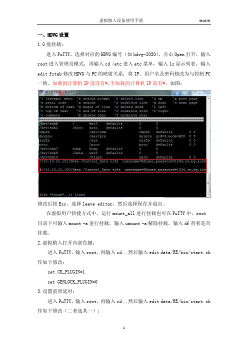
一、HDVG设置1.G盘挂载:进入PuTTY,选择对应的HDVG编号(如hdvg-2050),点击Open打开,输入root进入管理员模式,再输入cd /etc进入etc菜单,输入ls显示列表,输入edit fstab修改HDVG与PC的映射关系, 将IP、用户名及密码修改为与控制PC 一致。
加载的计算机IP前没有#,不加载的计算机IP前有#。
如图:修改后按Esc,选择leave editor,然后选择保存并退出。
在虚拟用户快捷方式中,运行mount_all进行挂载也可在PuTTY中,root 目录下可输入mount -a进行挂载,输入umount -a解除挂载,输入df查看是否挂载。
2.虚拟植入打开内部色键:进入PuTTY,输入root,再输入cd ..然后输入edit data/RE/bin/start.sh 作如下修改:set CK_PLUGIN=1set GENLOCK_PLUGIN=03.设置前景延时:进入PuTTY,输入root,再输入cd ..然后输入edit data/RE/bin/start.sh 作如下修改(二者选其一):unsetenv LD_PRELOAD /usr/lib/libdvg.sosetenv DVG_FRAME_DELAY 3setenv DVG_DELAY_BOARD 1setenv LD_PRELOAD /usr/lib/libdvg.sosetenv DVG_DELAY_CNT 24.接收传感器数据,开串口:进入PuTTY,输入root,再输入cd /dev,在dev目录下输入chmod 777 ttyS0 (S1)5、渲染通道与跟踪数据通道一致:进入PuTTY,输入root,在输入cd /data/RE/bin,在bin目录下输入edit RE.xml,修改RE.xml文件。
<Output1 ChannelId="0" Events="Yes" Statistics="No"/> 将ChannelID 改为和TrackingSet.cfg中的channel一致。
Nano SIM Tray P N 115U-A101 连接器说明书

Tray CL Conn. CL C5CD C6C1C2C7C3Tray EjectTray LockTray Push-InPICK UP AREA DATE CODE0151C o n t a c t H e i g h t S o l d e r t a i l scavity no.2020/04/06 mm1INITIAL RELEASE FROS 2020/07/31Fros DRAWN NAME:A B CAB CDEF G DE F GUNLESS OTHERWISE SPECIFIED TOLERANCE X.XX X.XX.LINEAR ANGLESDECIMAL UNIT: DRAWNNano SIM Socket, 6 Pin,123654DATE CODE: 0151 (YWWD)Y=YEAR(2020)WW=WEEK(01-52)D=DAY(1-7)This part is a connector only, it should be used together with Nano SIM Tray P/N:115U-T001Tray CLConn. CL Tray Eject Tray Lock PitchPCB edgeC1C2C3C5C6C7C5CD C6C1C2C7C3Recommended PCB layout (top view)I/O VPP GND CLK RST VCC Pin Name Pin NO.C 1C 2C 3C 5C 6C 7Card Detect SwitchCD CD C5Tray inserted CD C5Tray Ejected Pin out & Card detect switch status.Nano SIM Card Tray Push-InTray with card Tray without card CD C5CD C5Tray inserted Tray Ejected 2020/04/06 mm Fros DRAWN NAME:A B CAB C D E F GDEF G UNLESS OTHERWISE SPECIFIED TOLERANCE X.XX X.XX.LINEAR ANGLESDECIMAL UNIT: DRAWNNano SIM Socket, 6 Pin,SPECIFICATION:1. ELECTRICAL 1.1 Current Rating: 0.5A per pin 1.2 Voltage Rating: 10V DC 1.3 Contact Resistance: Max.1.4 Insulation Resistance: 1000M 1.5 Dielectric Withstanding Voltage: 500VAC 2.MECHANICAL 2.1 Durability: 5,000 cycles2.2 Contact Normal Force: 0.5N Min. per pin3.ENVIRONMENTAL3.1 Operating temperature range: -40 ~+3.2 Storage temperature range: -40 ~+4.SOLDER ABILITY 4.1 Recommended IR-Reflow Temperature: 260NO.PART NAMEDESCRIPTION1HOUSING LCP, UL94V-0, Black Phosphor Bronze, Gold plating over Nickel 2CONTACT3SHELL Stainless Steel, Nickel plating 4SLIDER LCP, UL94V-0, Black 5SPRING SWP-B, Nickel plating 6CRANK Stainless Steel *115U-T001Card Tray, Used for Nano SIM Card Socket Push-Push, Lock, PC+ABS, Black, ReelThis part is a connector only, it should be used together with Nano SIM Tray P/N:115U-T001A.Set up Nano SIM cardSnap-1Snap-2Snap-3Snap-4B.Remove Nano SIM card Step 2. Press another side untilit fixes by the snaps.Step 1. Insert the card with angle in the snaps.Press the back of the card to make it detach from the snaps.Tray insert directionInappropriate way of inserting tray may cause irreversible damage .Text side up C. Tray insert in connectorFool-proofing track Fool-proofing beveled cornerTray front 2020/04/06 mmFros DRAWN NAME:A B C AB CD E F G DEFGUNLESS OTHERWISE SPECIFIED TOLERANCE X.XX X.XX.LINEAR ANGLES DECIMAL UNIT: DRAWNNano SIM Socket, 6 Pin,Instruction ManualRecommended Panel CutT r a y P u s h -I nT r a y L o c kT r a y E j e c t Front view Top view Side section viewP C B POST2020/04/06 mmFros DRAWN NAME:A B C ABC DE F G DEF GUNLESS OTHERWISE SPECIFIED TOLERANCEX.XX X.XX.LINEAR ANGLESDECIMAL UNIT: DRAWNNano SIM Socket, 6 Pin,Instruction Manualabout 240mmabout 240mm DIRECTION OF FEEDPEELING ANGLE components no components no components winding the cover tape around the outerperiphery in a turn Tape & Reel6 Reel / 1 PE Bag Drier 4 Void FillerWaterproof PE Bag2020/04/06 mm PACKAGING SPECIFICATION:1. MATERIAL 1.1 Embossed Carrier Tape: PS Black 1.2 Top Cover Tape: PET 20-80g(Peel Speed 300mm/Minute)1.3 Taping Reel: Paper2. PACKING2.1 Quantity:700 Piece/Reel4,200 Piece/Carton 1INITIAL RELEASE FROS 2020/04/06FrosDRAWN NAME:A B C A BCD E FG D EF GUNLESS OTHERWISE SPECIFIED TOLERANCEX.XX X.XX.LINEAR ANGLESDECIMAL UNIT: DRAWN Nano SIM Socket, 6 Pin,*texture surfaceNOTE:1.MATERIAL:PC/ABS,UL 94V-0 Rated, Color black.2.RoHS + HF COMPLIANT PRODUCTS.2020/04/27 mm1INITIAL RELEASE FROS 2020/04/29Fros DRAWN NAME:A B C A BCD E F G D E F GUNLESS OTHERWISE SPECIFIED TOLERANCEX.XX X.XX.LINEAR ANGLESDECIMAL UNIT: DRAWN Nano SIM Card Tray,Finish:SECTION A-A AA*****texture surface 2020/04/27 mmsee sheet one Fros DRAWN NAME:A B C A BCD E F G D EF G UNLESS OTHERWISE SPECIFIED TOLERANCE X.XX X.XX.LINEAR ANGLES DECIMAL UNIT: DRAWNNano SIM Card Tray,。
GEM-PXCV 近距离读卡器覆盖安装说明书
R333 Bayview Avenue Amityville, New York 11701For Sales and Repairs, (800) 645-9445 GENERAL DESCRIPTIONThe GEM-PXCV is a durable hard plastic snap-on cover de-signed to replace the standard cover of the HID Model 6005B proximity card reader when used with a GEM-ACM1D Ac-cess Control System. These instructions detail the mounting and wiring procedures for the reader, and the installation of the GEM-PXCV cover.There are 3 LEDs associated with this combination:•The HID Model 6005B LED which provides the status of the access condition (door "locked" or "unlocked"). See Table 1.•Two LEDs within the GEM-PXCV which provide the status of the system condition (system "armed" or "disarmed") associated with the access Area (see Table 2).Together, the GEM-PXCV is an indoor/outdoor proximity card reader providing potted electronics, low power con-sumption and durability all in a small, easy-to-install package.LED IndicationsThe HID Model 6005B reader contains a multicolored LEDwhich provides visual feedback as to access condition when access cards are presented to the reader.Table 1 below displays the LED indications and their meanings.The GEM-PXCV module provides two LED's toindicate system status, as displayed in Table 2 below:Stealth Mode is used to hide the ACM’s Armed and Status LEDs. When Stealth Mode is enabled, the GEM-PXCV sys-tem status LEDs are normally off but are turned on for 1 min-ute by any of the following events: •Press a request to exit button •Press a request to arm button•Present a valid ARM/DISARM or ARM card to the reader When Stealth Mode is disabled ("normal operation"), the LED's are always enabled and mimic the Keypad Status LEDs for the following functions only: Armed , Disarmed , Ready to Arm , Not-Ready to Arm and Alarm . Note: When the system is in alarm, Stealth Mode is disabled. "Access Only" cards do not affect the status of Stealth Mode.MOUNTING THE GEM-PXCVBefore mounting the card reader, always plan ahead and deter-mine the route all wires will follow before drilling into wall mount-ing surfaces. For more information regarding various system designs, refer to WI1121 for complete installation instructions. Install the GEM-PXCV as follows:Table 3: Proximity Card Reader ConnectionsGEM-ACM1D Termi-nal NumberGEM-ACM1D TerminalDescriptionHID Model 6005B (Prox PointPlus ) Wires17 (+) Reader Power Red (+ DC)18 (-) Reader Power Black (- Ground) & (ShieldedGround)19 Reader Data 1 White (Data 1) 20 Reader Data 0 Green (Data 0) 21 (-) Red LED Brown (Red LED) 22 (-) Red & Green LED Orange (Green LED) 23 (-) Reader Sounder Yellow (Beeper) (Not Used) (Not Used) Blue (Hold) (Not Used)(Not Used)Violet (Card Present)* Tamper Connection not available on HID 6005BBe sure to place jumper JP1 in correct configuration for 5 volt or 12 volt reader operation.Table 1: (Top) Access Status LED (HID Model 6005B)LED INDICATIONACCESS CONDITIONSteady Red Door Locked Steady Green Door UnlockedMomentary Green Card Read--Door Remains Locked Alternating Green & Red(Downloading PCD-Windows Program to ACM)Table 2: (Bottom) System Status LED's (GEM-PXCV)LED INDICATIONSYSTEM CONDITIONSteady Red System Armed Red LED is off System Disarmed Blinking Red System in Alarm Steady Green System Ready to Arm Green LED is offSystem Not Ready to ArmTable 4: GEM-PXCV Wire ConnectionsGEM-PXCV WiresGEM-ACM1D Terminal Description GEM-ACM1D Terminal Number GEM-2D Terminal NumberRed Reader Power 17 (+) 35 (+) Orange Active Low Red Armed LED 30 48 GreenStatus Green LED3149SystemStatus LED's(see table 2)AccessStatus LED (see table 1)1.Determine mounting location. Using the template (Figure 1) and a pencil, lightly mark the location of the two mounting holes and the two wire feed holes.2.Route the HID Model 6005B wires. The minimum number of wires required to activate the HID Model 6005B are dis-played in Table 3. Determine which wires will be needed and plan how these wires will be accessed from behind the mounting location.3.Install dry wall mounting hardware. Use hardware such as molly bolts, toggle bolts or other anchoring devices. Drill the smallest hole needed for the device. Warning: Use caution when drilling holes--there may be high voltage wir-ing in wall.4.Drill wire feed holes. Minimum size for the top feed hole (A) is 1/2", but can be made larger if necessary. Note: Do not exceed a diameter that can be concealed by the GEM-PXCV reader cover. The diameter of the bottom feed hole (B) should not exceed 1/2" and should be made as small as possible. Note: Use care to ensure that the bottom feed hole (B) does not damage the structural integrity of the bot-tom mounting hole anchoring device.5.Route the HID Model 6005B wires from behind the mount-ing location through the top wire feed hole (A).6.Insert the 3 LED System Status wires into the bottom wire feed hole (B) and then out of the top wire feed hole (A).7.Connect the HID Model 6005B wires as displayed in Ta-ble 3. Connect the GEM-PX wires as displayed in table 4, below.8.Note: Do not apply power until all wiring is complete.9.Push all wires back into wall . Use care not to damage the wiring or the mounting surface.10.Mount HID Model 6005B Reader Base using two #4mounting screws (supplied).11.Install cover . Place the GEM-PXCV proximity reader coverover the HID Model 6005B base and snap on to secure.NOTE ON READER TYPEThe type of HID Model 6005 Reader used and the PCD-Windows setting "Enable Card Presentation Beep and Green LED Flash" will determine the exact operation of the Access Status LED (see Table 1) as shown below:HID MODEL 6005B-00 (Recommended)•Setting Disabled: Green LED will operate when card is read. •Setting Enabled: Green LED will double flash when card is read.HID MODEL6005B-07•Setting Disabled: Green LED will not flash when card is read. •Setting Enabled: Green LED will operate when card is read.NAPCO SECURITY SYSTEMS, INC. (NAPCO) warrants its products to be free from manufacturing defects in materials and workmanship for thirty-six months following the date of manufacture. NAPCO will, within said period, at its option, repair or replace any product failing to operate correctly without charge to the original purchaser or user. This warranty shall not apply to any equipment, or any part thereof, which has been repaired by others, improperly installed, improperly used, abused, altered, damaged, subjected to acts of God, or on which any serial numbers have been altered, defaced or removed. Seller will not be responsible for any dismantling or reinstallation charges. THERE ARE NO WARRANTIES, EXPRESS OR IMPLIED, WHICH EXTEND BEYOND THE DESCRIPTION ON THE FACE HEREOF. THERE IS NO EXPRESS OR IMPLIED WARRANTY OF MERCHANTABILITY OR A WARRANTY OF FITNESS FOR A PARTICULAR PURPOSE. ADDITIONALLY, THIS WARRANTY IS IN LIEU OF ALL OTHER OBLIGATIONS OR LIABILITIES ON THE PART OF NAPCO. Any action for breach of warranty, including but not limited to any implied warranty of merchantability, must be brought within the six months following the end of the warranty period. IN NO CASE SHALL NAPCO BE LIABLE TO ANYONE FOR ANY CONSEQUENTIAL OR INCIDENTAL DAMAGES FOR BREACH OF THIS OR ANY OTHER WARRANTY, EXPRESS OR IMPLIED, EVEN IF THE LOSS OR DAMAGE IS CAUSED BY THE SELLER'S OWN NEGLIGENCE OR FAULT.In case of defect, contact the security professional who installed and maintains your security system. In order to exercise the warranty, the product must be returned by the security professional, shipping costs prepaid and insured to NAPCO. After repair or replacement, NAPCO assumes the cost of returning products under warranty. NAPCOshall have no obligation under this warranty, or otherwise, if the product has been repaired by others, improperly installed, improperly used, abused, altered, damaged, subjected to accident, nuisance, flood, fire or acts of God, or on which any serial numbers have been altered, defaced or removed. NAPCO will not be responsible forany dismantling, reassembly or reinstallation charges.This warranty contains the entire warranty. It is the sole warranty and any prior agreements or representations, whether oral or written, are either merged herein or are expressly canceled. NAPCO neither assumes, nor authorizes any other person purporting to act on its behalf to modify, to change, or to assume for it, any otherwarranty or liability concerning its products. In no event shall NAPCO be liable for an amount in excess of NAPCO's original selling price of the product, for any loss or damage, whether direct, indirect, incidental, consequential, or otherwise arising out of any failure of the product. Seller's warranty, ashereinabove set forth, shall not be enlarged, diminished or affected by and no obligation or liability shall arise or grow out of Seller's rendering of technical advice or service in connection with Buyer's order of the goods furnished hereunder. NAPCO RECOMMENDS THAT THE ENTIRE SYSTEM BE COMPLETELYTESTED WEEKLY. Warning: Despite frequent testing, and due to, but not limited to, any or all of the following: criminal tampering, electrical or communications disruption, it is possible for the system to fail to perform as expected. NAPCO does not represent that the product/system may not be compromised or circumvented; or that the product or system willprevent any personal injury or property loss by burglary, robbery, fire or otherwise; nor that the product or system will in all cases provide adequate warning or protection. A properly installed and maintained alarm may only reduce risk of burglary, robbery, fire orotherwise but it is not insurance or a guarantee that these events will not occur.CONSEQUENTLY, SELLER SHALL HAVE NO LIABILITY FOR ANY PERSONAL INJURY, PROPERTY DAMAGE, OR OTHER LOSS BASED ON A CLAIM THEPRODUCT FAILED TO GIVE WARNING. Therefore, the installer should in turn advise the consumer to take any and all precautions for his or her safety including, but not limited to, fleeing the premises and calling police or fire department, in order to mitigate the possibilities of harm and/or damage.NAPCO is not an insurer of either the property or safety of the user's family or employees, and limits its liability for any loss or damage including incidental or consequential damages to NAPCO's original selling price of the product regardless of the cause of such loss or damage.Some states do not allow limitations on how long an implied warranty lasts or do not allow the exclusion or limitation of incidental or consequential damages, or differentiate in their treatment of limitations of liability for ordinary or gross negligence, so the above limitations or exclusions may not apply to you. This Warranty gives you specific legal rights and you may also have other rights which vary from state to state. NAPCO LIMITED WARRANTY2.690"1.345"0.220"3.190"Mounting HoleMounting HoleTop Wire FeedHole (A)Bottom Wire Feed Hole (B)GEM-PXProximity Reader TemplateTHIS PAGE INTENTIONALLY LEFT BLANK。
虚拟SIM卡使用说明
﹥ 苹果用户打开“设置”→“电话”→“SIM 卡应用程序”。 ﹥ 安卓用户插入 SIM 卡后会在桌面自动生成一个“USIM 卡应用”,或者“设置” →
“应用管理” →“所有应用程序” →打开“USIM 卡应用”。
2. 添加卡号
﹥ 支持两种方式添加 SIM 卡数据 a. 添加卡号 → 按 SIM 卡数据分类在对应位置填写入相应的数据 。
b. 快捷写号 → 按固定格式编辑 SIM 卡数据,每次可以填入整张卡的数据 。 4G 数据格式: TAG=FFFFFFFFFFFFFFFF;ICCID=FFFFFFFFFFFFFFFFFFFF;IMSI=FFFFFFFFFFFFFFF;KI=FF FFFFFFFFFFFFFFFFFFFFFFFFFFFFFF;OPC=FFFFFFFFFFFFFFFFFFFFFFFFFFFFFFFF;+86FF FFFFFFFFF; 2G 数据格式: TAG=FFFFFFFFFFFFFFFF;ICCID=FFFFFFFFFFFFFFFFFFFF;IMSI=FFFFFFFFFFFFFFF;KI=FF FFFFFFFFFFFFFFFFFFFFFFFFFFFFFF;+86FFFFFFFFFFF; 数据中的红色文件头和分号需要保留,用户将 F 替换成自己 SIM 卡中的对应数据, +86FFFFFFFFFFF 为短信中心号码。 TAG:号码标识,不能含有“空格”只支持 4 个字符的 Unicode,用户需要将填写的内容 通过工具转换成 Unicode(“添加卡号”中的“号码标识”不需要转换) 。 Unicode 在线转换工具 /chinese2unicode.php TAG 实例:号码标识需要填入的内容为“V 多号卡”,打开在线转换工具,输入“V 多号卡”, 点击“中文汉字转 Unicode”,工具输出“\u0056\u591a\u53f7\u5361”,去掉“\u”,最 终取值“0056591a53f75361”,TAG=0056591a53f75361。
博世 FLEXIDOME HD VR 安装手册说明书
2
简介
2.1
特性
3 3.1 3.1.1 3.1.2 3.1.3 3.1.4 3.1.5 3.1.6 3.1.7 3.1.8 3.1.9 3.1.10 3.1.11 3.1.12 3.1.13 3.2
系统信息 网络视频服务器 逐行扫描 真正的日夜两用功能 多个数据流 ONVIF (开放式网络视频接口论坛) 音频 报警输入 / 输出 破坏检测和移动探测 视频编码 组播 以太网供电 加密 录像 配置 与外部系统配合使用
4
规划
4.1
拆开包装
4.2
系统要求
Bosch Security Systems
安装手册
目录 | zh 3
5 5 6 7 7 8 8 8 10 10
12 12
13 13 13 13 13 13 13 13 13 14 14 14 14 14 14 15
16 16 16
AM18-Q0637 | v1.0 | 2012.12
FLEXIDOME HD VR
1.2
重要安全说明
阅读、遵循以下所有安全说明并保留以备参考。 在操作装置之前,请 遵循装置上的所有警示以及操作说明中的所有警告信息。 1. 只能使用干软布清洁。请勿使用液体清洁剂或喷雾清洁剂。 2. 不要在靠近热源的地方安装装置,例如散热器、加热器、火炉或
其它生热设备。 避免长时间暴露在直射阳光下。 3. 不要让任何液体溅入装置。 4. 采取预防措施,防止雷电或电源线上的电涌损坏装置。 5. 请仅调节操作说明中指定的控件。 6. 仅使用标签上指定的电源类型为装置供电。 7. 除非是合格人员,否则不要尝试自行维修已损坏的装置。所有维
12 VDC / 24 VAC 电源:此装置使用限定电源进行操作。装置使用 12 VDC 或 24 VAC 电源 (如果 PoE 不可用)。用户实施的布线必须符 合电气规则 (2 类电源级别)。 PoE:仅使用认证的 PoE 设备。在连接 12 VDC 或 24 VAC 电源的同 时,也可以使用以太网供电 (PoE)。 如果同时使用辅助电源 (12 VDC 或 24 VAC)和 PoE,摄像机将选 择辅助电源,并且会关闭 PoE。
vive 无线套件商用版安装说明书
BE-01H-UG-01 VIVE 无线套件商用版安装说明书包含物说明主要部件说明连接说明安装软件客户端使用步骤PC发射端架设说明注意事项产品常见问题扫码查看无线套件安装视频使用产品前,请先阅读用户安装指南。
非印刷版的安装指南将定期更新以提升准确性和完整性。
要获得最新版本,请查看 。
TPCAST客服热线:400-7009-566一、包含物说明② *PC 发射端 x2③ *电源盒 x2⑦ *尼龙网袋 x2⑧ 说明书及搭建方案 ④ *移动电源 x2⑤ *专用长连接线 x2⑥ *短连接线 x2注:*标记的配件在四人套中数量为4。
⑨ 路由器 ① *头盔接收端 x29101112*网线 x211*腰带 x212*支架 x213⑩ 路由器电源12374二、主要部件说明1、头盔接收端2、PC 发射端①HDMI 接口 ④云台固定接口②电源接口⑤视频连接信号指示灯③视频连接配对按钮①头带及线缆通过孔 ④USB 线接口②HDMI 短连接线接口 ⑤视频连接配对按钮③视频连接信号指示灯3、电源盒4、移动电源①专用长连接线电源接口 ②专用长连接线U SB 接口③移动电源US B 接口④指示灯①U SB 电源输出孔③电量查看指示按钮②Micro USB 电源充电口 ④电量指示灯5、路由器①网线接口WAN口②网线接口LAN口③路由器电源适配器接口④路由器工作状态指示灯6、线材专用长连接线1-C三、单机连接说明短HDMI 连接线第一步:拆除原有连接线缆① 通过图示角度,打开头盔顶部连线顶部舱盖 。
1、头盔接收端连接说明2请将无线套件三个主要组成部分按壳体标识的数字签分好,分别组装在相应的V IVE 头盔上,长连接线和HDM I 短线无需区分,可通过,单机组装操作如下:②拔掉三合一连接线三个接头及音频线接头,总计4个。
③将三合一连接使之与头盔彻底分开。
④分开头部滑带与舱盖的连接部分。
第二步:固定头盔接收端① 如图所示,将专用长连接线1-A 、1-B 、1-C 三个接头及音频线接头,自头盔接收端有T PC AST 字样的一侧穿入,从另一侧穿出。
- 1、下载文档前请自行甄别文档内容的完整性,平台不提供额外的编辑、内容补充、找答案等附加服务。
- 2、"仅部分预览"的文档,不可在线预览部分如存在完整性等问题,可反馈申请退款(可完整预览的文档不适用该条件!)。
- 3、如文档侵犯您的权益,请联系客服反馈,我们会尽快为您处理(人工客服工作时间:9:00-18:30)。
虚卡像机安装说明
1、虚卡像机安装流程:
2、安装场景说明
1)主机安装在场景正中央;
2)杆件高6米;
3)常亮灯距离像机应不小于2米;
4)如图2.1-1以3车道为例展示系统安装方式
图2.1-1系统安装方案图备注:相机采用变焦镜头,场景可通过镜头调整覆盖1—3车道。
3、系统布线总图:
纯视频检测系统布线图
4、设备初始化
步骤1
1、将网线一端接入 PC 网口,将网线另外一端接入设备网口。
2、将 PC 的 IP 地址与设备的 IP 地址设置为同一网段。
网段为 192.168.1.X,但不能与设备出厂 IP 地址 192.168.1.108 重复。
3、在 PC 上执行 ping ***.***. ***. ***(设备 IP 地址)命令,检验网络连通情况。
步骤2
给电脑主机和设备分别设置 IP 地址、子网掩码和网关。
如果网络中没有路由设备,请分配同网段的 IP 地址。
如果网络中有路由设备,则需要设置好相应的网关和子网掩码。
步骤3
在浏览器中输入设备的 IP 地址,按【回车】键后,登录 WEB 界面。
步骤4
在弹出的登录界面中,输入用户名和密码,默认用户名和密码均为 admin,单击“登录”。
说明:
对于需要初始化的设备,先初始化再使用。
图6-1 登录界面
步骤5
首次登录成功后,进入配置向导,系统提示您修改密码。
图6-2 配置向导(1)
步骤6
配置完成后单击“下一步”,修改设备 IP 地址、子网掩码、默认网关。
图6-3 配置向导(2)
步骤7
修改完成之后单击“完成”,可直接进入 WEB 主界面。
说明
如果首次登录 WEB 界面,请根据系统提示安装或加载控件。
安装控件前,请确保“Internet 选项 > 安全”中,active 相关的控件选项已改为“启用”或“提示”。
5、设备聚焦
即自动后焦调整功能,可一键完成精确的后焦调节。
配置步骤如下:
步骤1
选择“设置 > 相机设置 > 摄像头属性 > 聚焦”。
系统显示“聚焦”界面,如图 6-51 所示。
步骤2
拖动滑块,设置步长大小。
说明:
单击 +或- ,也可设置步长大小。
步骤3
单击“步长”面的下拉框,设置 ABF 调节的速度,选择的数值越大,调节速度越快。
步骤4
单击“自动聚焦”,设备自动在监控画面范围内聚焦。
6、设备画线与通道名称设置
6.1车道属性
设置车道信息并对事件进行配置,卡口对应不同的事件配置。
选择“设置 > 智能交通 > 车道属性”,界面如图 6-22 所示,设置完成
后单击“确定”,使配置生效。
6.2智能分析- 场景配置
绘制场景的区域线、车道线和检测线,并进行设置。
步骤1 选择“设置 > 智能交通 > 智能业务 > 智能分析 > 场景配置”。
界面如图 6-26 所示,参数说明请参见表 6-14。
特殊说明:
检测线在画面中间,23米位置。
区域先占屏幕二分之一,均匀分布检测线两侧。
车辆区域先占屏幕四分之一,均匀分布检测线两侧。
画线说明:
6.3视频 OSD
设置视频通道的 OSD 信息,内容包括通道标题、时间标题、GPS 标题、流量信息、车辆队尾信
息及自定义标题。
具体步骤如下:
步骤1 选择“设置 > 智能交通 > OSD 设置 > 视频 OSD”。
步骤2 选择“字体大小”和“字体方案”,设置字体和字号。
步骤3 设置通道标题和位置。
步骤4单击“确定”,使配置生效。
6.4图片 OSD
设置图片的 OSD 信息和位置。
具体步骤如下:
步骤1 选择“设置 > 智能交通 > OSD 设置 > 图片 OSD”。
界面如图 6-32 所示。
步骤2 选中画面任何区域拖动鼠标,可以增加图片标题。
移动方框到显示的位置,或在界
面右
下角 X/Y 方框内手动输入坐标值。
系统最多支持 8 个图片标题,每个图片标题可自定义 OSD 选项。
选中某一图片标题,单击右键,即可删除当前图片标题。
步骤3 选择 OSD 黑边的位置,包括上方、下方或无。
步骤4 设置 OSD 信息的字号和字体方案,在界面右下角设置图片 OSD 信息的字体颜色。
步骤5 单击“确定”,使配置生效。
6.5快门设置
设置快门、曝光、增益和情景模式。
选择“设置> 相机设置> 摄像头属性> 快门设置”,
圈红地方设置曝光自定义区间,0-2
设置完成后单击“确定”,使配置生效。