LX36-84限位开关说明书
WBB-36说明书(汉化版)
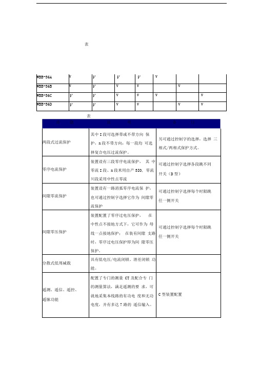
表表五(WBB-36B D型装置通道配置)5.1装置的启动元件启动元件作为所有保护功能的开放元件,起着重要的作用,本装置设有两个启动元件:突变量启动元件及电流辅助启动元件。
突变量启动元件利用相电流差突变量来计算,判据为:I =|(l (k)-l (k-N))-(l (k-N)-l (k-2N))|>IQD(N=12);其中为A,B,C中的任一项。
辅助启动元件为过流启动元件或零序过流启动元件,具体判据为:I >min(IL1 , IL2定值)(在相应的保护功能压板投入情况下);3IO>IJO定值(在相应的保护功能压板投入情况下);(C型)3I0>min(101,102,103定值)(在相应的保护功能压板投入情况下);(D型)其中为A,B,C中的任一项。
5.2复合电压元件复合电压元件由正序低电压和负序过电压经或门构成,变压器三侧电压均可作为闭锁电压引入,另外,可通过开入端子X70(对侧复压闭锁开入)和X69(另侧复压闭锁开入)选择由对侧/另侧复压元件来开放本侧电流保护,对应的,控制字中有相应的选择功能,可选择某一侧复压闭锁或多侧复压闭锁,选择多侧复压闭锁时,开放条件为”或”门,即任一侧复压满足开放条件即开放保护,I段和n段电流保护均可由控制字选择带或不带复合电压闭锁。
5.3两段过流元件设有复压过流I段和复压过流II段两块独立压板投/退保护功能。
启动元件动作后,装置进入两段相间过流判别。
本装置中复压过流I段设置了两个可以独立整定的延时时间,II段也设置了独立的延时时限,可通过控制字选择不同时限跳不同的开关。
装置在执行两段过流判别时,各段判别逻辑一致,其动作条件如下:1)I >Idn ; Idn为n段电流定值(n=1,2), I为最大相电流2)T>Tdn ; Tdn 为n 段延时定值(n=1,2,3)3)相应于过流相间的方向条件及复合电压条件满足(根据控制字的设置)过流I段可选择带方向,方向可选择指向变压器或母线.5.4两相式、三相式电流元件装置可根据控制字的设置,实现两相式或三相式保护方式,区别在于:两相式保护方式:弓I入IA , IC两相电流及假B相电流IB = -(IA+IC)到本装置,装置电流保护I段、II段均为两相式(只反映IA、IC两相电流),山段为三相式,主要是为了提高在经Y/ △变压器,在△侧故障III段保护的灵敏度。
Honeywell EX 防爆限位开关 说明书

电路 电气额定值单刀单掷 A UL/CSA 额定值15A 125250或480VAC; 1/8Hp, 125VAC; 1/4Hp,250VAC; 1/2A 125VDC; 1/4A 250VDC单刀双掷 B UL/CSA 额定值20A 125250或480VAC 10A 125VAC “L”1Hp 125VAC; 2Hp 250VAC; 1/2A 125VDC; 1/4A 250VDC单刀双掷 C UL/CSA 额定值10A 125或250VAC0.3A 125VDC; 0.15A 250VDC单刀双掷 D UL/CSA 额定值10A 125或250VAC0.3A 125VDC; 1/4A 250VDC单刀双掷 E 额定值1A 125VACSingle-Conduit Connect Switch*EX 开关带有列入UL 的用于危险环境的最小外壳外壳中的火焰能道冷却爆炸气体使其在到达外壳外部爆炸气体的环境之前温度低至燃点温度以下打开前盖可以看到用螺相紧固的开关单元EX 开关具有一个或两个导线也在开关体的单侧或双侧EX 开关对液体不密封不建议用于室外或有水浅的环境如果需要这类一茁壮成长可选用CX 或LSX系列特点:• NEMA179• 紧凑坚固的外壳 • 高达20A 的负载能力 • 宽敞的接线空间 • 可从四个侧面固定 • 滚轮摇杆位置360°可调 • 不产生火花的执行杆 • 附带在盖上的螺钉 • ULCSA 认证 • 接地螺钉NEMA 标准: 17和9UL 和CSA 认证: Class1Div.1GroupsB(仅限于800EXH 系列和EXD 系列)C 和D; Class II Div.1GroupsE,F 和G温度范围: -40~71°C电气额定值电气额定值型号Q.F NP.T.max. mm O.T. minD.T. max. mm 顺时针15A SPDT A EX-AR 2.22-5.56 5.56 (8°)90° 0.18 (0.25°) 顺时针20A SPDT B EXA-AR 3.34-8.90 5.56 25° 0.3 (4°)逆进针15A SPDT A EX-AR30 11.1 2.65 25° 0.18(0.25°)顺时针或逆时针15A 低操作力(无回复弹簧)不带安装支架SPDTA EX-AR160.56-- -附加转杆订EX-AR20时需从下图中选择转杆顺时针, 15A SPDT A EX-AR800 2.22-5.56 5.56 90° 0.18(0.25°)逆时针 15A SPDT A EX-AR83011.1 1.65 25° 0.18(0.25°)顺时针 10A DPDT C EX-D-AR-3* 2.22-6.67 6.35 25° 2.77(4°)逆时针 10A DPDT C EXD-AR30-3* 12.2 5.56 25° 2.77 滚轮转杆 6PA5-EX表铜滚轮6PA127-EX尼龙滚轮顺时针1A**SPDTE EXH-AR3 2.22-6.67 5.56 25° 0.64附加 UL,CSA 认证用于 Class1Group B,(氢气环境)逆时针 1A**SPDTE EXH-AR3311.1 1.65 3.525° 0.64不带转杆(选择转杆参见左图)顺时针SPDTA EXH-AR20 0.22Nm 5.56 90° 0.18(0.25°)正交滚轮转杆 6PA131-EX青铜滚轮逆时针其余同上A EXH-AR230 0.22Nm 5.56 90° 0.18(0.25°)单向滚轮转杆 顺时针6PA130-EX 青铜滚轮 逆时针6PA142-EX青铜滚轮顺时针或逆时针的转动方向为从商标面看过去的方面 *带3英尺引线**内部开关单元为真空密封开关带3.2米引线工作特性: O.F.操作力; P.T.-预行程; O.T.过行程; D.T.差动行程可调长度滚轮转杆6PA138-EX尼龙转杆棒式转杆6PA136-EX铝棒可调长度12.5英寸棒式转杆 带1英寸尼龙滚轮滚轮转杆开关选型表形式电气额定值型号 O.F.max. N P.T. max. mm O.T. min D.T. max. mm 顺时针15A SPDT不带安装支架A EX-AR1613 0.56 18° 90° -正交滚轮转杆开关选型表过行程柱塞式开关手动操作开关低力扫描仪转杆开关单向滚轮转杆开关形式电气额定值型号 O.F. N P.T.max. mm O.T. min D.T. max. mm 顺时针15A SPDTA EX-CR 2.22-5.56 5.56 90° 0.18选型表形式电气额定值型号 O.F. N P.T.max. mm O.T. min D.T. max. mm 顺时针15A SPDTA EX-AR128 2.22-5.56 5.56 90° 0.18选型表选型表形式电气额定值型号 O.F. N 3×3.5英寸踏班 SPDT不带安装支架A EX-AR50 11.1选型表形式 电气额定值型号 O.F. max. N P.T.max. mm O.T. min D.T. max. mm O.P.* mm 15A,SPDT A EX-Q 13.34 2.98 4.78 0.1 47.22 20A,SPDT B EXA-Q 8.9 1.27 3.18 0.23 46.0215A, SPDT A EX-Q800 13.34 1.98 4.78 0.1 47.22 附加ULCSA 认 证用于 Class1, Group B, (氢气环境)10A, DPDT C EXD-Q-3** 13.34 3.96 3.58 1.52 46.02 带密封靴10A,SPDTD EX-N15 13.34 1.98 4.78 0.1 52.32公差为±0.06毫米**带3英尺电缆操作特性: O.T.-操作力; P.T.-预行程; O.T.-过行程; D.T.-差动行程形式 电气 额定值 型号O.F.max.N P.T. max.mm O.F. min D.T. max. mm 两个1/2英寸的出线孔 顺时针15A SPDT A 1EX1 2.22 5.56 5.56 0° 0.18 两个1/2英寸的出线孔 顺时针20A SPDT B 1EX1 3.618.90 5.56 25° 0.3 两个3/4英寸的出线孔 顺时针10A DPDT C 4EX13* 2.22 6.67 6.35 25° 2.77双出线孔开关 本页所示的开关为双出线孔式开关便于穿过式接线用户还可利用这一特点将DPDT开关的两路接线分别从不同的出线孔引出外壳尺寸比单出线孔的EX 开关大一些提供了附加的接线空间NEMA双出线孔的EX 开关具有与单出线孔开关相同的密封防爆等级选型表滚轮转杆开关*带3英寸长电缆操作特性: O.F.-操作力; P.T.-预行程; O.T.-过行程; D.T.-差动行程安装支架安装尺寸15PA85EX 用于从顶部底部 15PA86EX 仅用于从顶部固定柱或后部固定EX 塞式开关滚轮转杆式EX 开关也可直接固定用1032UNF 螺钉不带滚轮转杆安装尺寸正交滚轮转杆单向滚轮转杆低操作力棒式手动操作式柱塞式带密封靴柱塞式带双出线孔的开关滚轮转杆。
东崎电气接近开关使用说明书

接近开关使用说明书感谢您对广东东崎电气有限公司产品的信赖,当您使用我公司产品时请务必参阅本说明,以免因操作失误而造成不必要的损失。
例:TKI-12N4C表示直插式插头连接型,直流电感式接近开关,外形为M12圆柱型,NPN常开,动作距离为4mm,最大输出电流为200mA.二、距离的设定※开关的动作距离请设定在80%检测距离(Sn)内,以免开关工作受温度、电压等影响。
※当检测其它金属时,开关有不同的动作距离。
(图1)※当开关用作测量动作频率或其它高速场合,请将开关的动作距离设定在1/2检测距离(Sn),开关在此位置可获得最大的动作频率。
※电容式接近开关的动作距离设定,请参阅电容式接近开关的使用说明。
(见五)不锈钢铬镍铜铝二、接线图PNP(直流型)三、串联及并联NPN(直流型)直流二线型检测距离交流二线型(图1)电源电源交流串联交流并联若电源电压为220V,且串联数在3个以内,可使用上图的接法,否则请按下图方法通过继电器进行串联。
并联的开关A和B,若检测体接近开关A,开关A动作,负载电流流过开关A,开关A(B)两端电压降为10V,若此时检测体再接近开关B,因开关两端的电压为10V,开关B会因电压不足而不动作,只有当关闭开关A,使A(B)两端的电压升高至使用电压,开关B才动作,开关A关闭与开关B动作的时间间隔约为10mS,因而当需要多个接近开关并联时应注意开关相互之间的影响,一般请按下图通过继电器进行并联。
电源AC 电源※直流电源必须使用绝缘变压器,请勿使用自耦变压器;※电力线、动力线通过开关引线附近时,为防止开关误动作和损坏,请使用金属配管线。
四、注意事项※交流型开关,若电源电压为110V时,串联必须经过继电器使用;※交流型开关必须经过负载接电源,若直接将开关接电源会损坏开关。
电源AC 电源×错误接法√正确接法※接近开关的引线长度请在200米以下,以免电压降过大。
五、电容式接近开关的使用说明※电容式接近开关不仅能检测金属,而且能检测塑料、玻璃、水、油等物质,因各种检测体的导电率和介电常数、吸水率、体积的不同 故相应检测距离也不同,对于接地的金属可获得最大的检测距离。
施耐德电气 CA-Series 带 2 个和 4 个滑轮的带电锁自动门限位器 说明书

53
CA-40-6� 40"
6,000
2"
55 lbs. / 35 lbs. UPS
58
CA-48-2� 48"
2,000
2"
35 lbs. / 20 lbs. TRUCK
58
CA-48-4� 48"
4,000
2"
45 lbs. / 25 lbs. TRUCK
61
CA-48-6� 48"
6,000
2"
Manual Carousels
The Carousel rotates materials 360° with the assistance of an operator. Now loading and unloading operations can be done more efficiently; minimizes fatigue and risk of back injury. The carousel may be added to an existing work bench, scissor table, or simply placed on the floor. Constructed from two pieces of rolled structural angle (3/16" thick). A series of roller bearings transfer the load smoothly and evenly to the supporting surface. Four guide rollers keep the rings aligned.
FOOT OPERATED LOCKING DETENT LOCKS CAROUSEL EVERY 90° model CA-FTK
3610L说明书
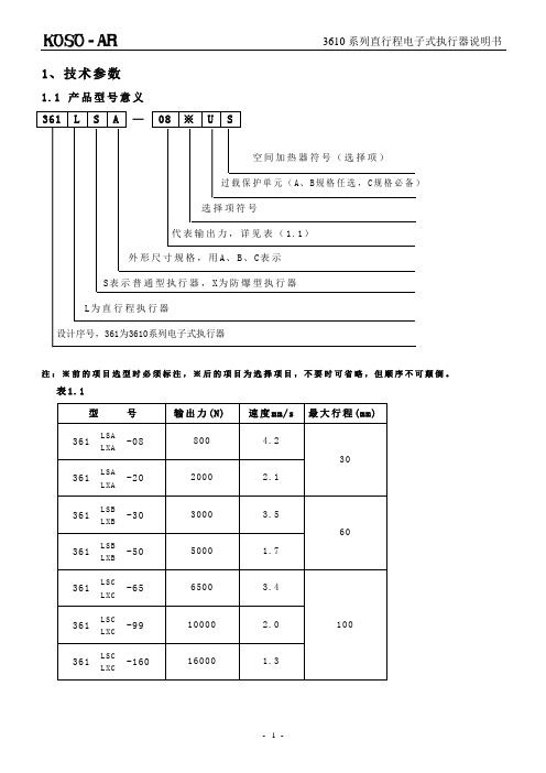
1、技术参数1.1 产品型号意义注:※前的项目选型时必须标注,※后的项目为选择项目,不要时可省略,但顺序不可颠倒。
表1.11.2 结构1.2.1 361普通型结构图图1.11.2.2 361防爆型结构图图1.21.3 主要技术参数表1.21.4 安装尺寸图1.3注:表中h1是输出轴位于最下端时的尺寸,H2是拆卸护罩所必须的尺寸,R是手动曲柄操作所必须的尺寸,在设计安装时应予以考虑。
2、工作原理3610系列电子式执行器是以220V单相交流电源作为驱动电源,接受来自计算机、调节器或操作器4~2 OmAd·c、或1~5 Vd·c输入信号来工作的电子式执行机构。
电子控制单元采用集成电路制做,被设计成匣子形式,并用树脂浇铸固化,称为控制模块,本身具有伺服功能。
当控制模块接受的变化输入信号4~2OmAd·c(或1~5 Vd·c)和来自反馈机构的开度信号进行比较、放大后,向消除其差值的方向驱动和控制电机。
电机的旋转通过减速机构把动力传递到输出轴上,使其上、下运动,同时通过反馈机构带动电位器转动,电位器的动作变换成电气信号后,作为开度信号反馈给控制器。
当输入信号和开度信号的差值达到设定的灵敏度范围时,电机停止转动,起到定位调节作用。
3、接收、搬运及保管3.1 接收、搬运警告执行器系重量物体,使用时应注意以下事项,否则可能导致重大人身伤害事故。
●应按照劳动安全卫生法,使用符合要求的提升机械进行卸货、搬运。
绝对不许进入吊起的货件下或在吊件下操作机械。
●设备用纸盒箱包装时,如受潮,会使包装强度下降,所以一旦纸盒箱受潮吊卸必须注意。
●避免受到冲撞、滑落等急剧的冲击。
3.2 保管●在安装之前最好在原包装状态下保管。
●请勿在以下场所保管:(1)可能淋到雨水的地方(2)60℃以上的高温环境(3)灰尘大的环境(4)湿度高的环境●避免受到冲撞、滑落等急剧的冲击。
●从检查打开包装后到开始往阀上安装前,最好再按到货时的包装状态保管。
【VIP专享】LX电动单梁悬挂起重机介绍使用说明书

LX电动单梁悬挂起重机说明书目录一·产品概况-----------------------------------1二·外形总图与主要技术参数--------------2三·安装、调试--------------------------------3四·使用与维护--------------------------------4五·电器控制原理图--------------------------5六·易损件--------------------------------------6一、产品概述1.1 主要技术条件LX型电动单梁悬挂起重机的设计制造遵循《电动单梁悬挂起重机》JB2603-94标准,与CD1、MD1等电动葫芦配套使用,成为一种有轨运行的轻小型起重机。
一般起重机在0.5~5T,跨度3~16m,运行速度20m/min及30m/min,如果有特殊要求的可另外设计制造。
1.2 使用范围LX型起重机工作级别为A3~A5,工作环境-25℃~45℃,相对湿度≤85%,适用在无易燃、易爆物品及腐蚀介质条件工作。
融化金属、剧毒物品慎用!该起重机因其其有结构紧凑、刚性好、操作灵敏、噪音低、无污染、安全可靠等有点广泛用于工矿企业、仓库、料场等场所。
该起重机工作电源:AC 380V 50Hz,也可以根据客户要定制。
1.3 基本结构LX型起重机主要由主梁、横梁、电动小车、电器、起升结构组成。
电动小车、从动小车与CD1型小车通用,具有较好的通用性和互换性。
一般情况0.5t跨度3~16m:1t跨度小于12m:2t跨度小于等于7.5m时可不配备横梁,也可根据用户需要配备横梁。
横梁轮距随起重机重量及跨度不同而不同。
详细情况见表1、表2、表3.电机电器性能及参数符合JB834、ZJB80013.3及JB/T6391.2有关标准。
起升机构情况详见电动葫芦说明书。
LX型说明书
起重机试车
1、起重机的试运转包括试运转前的检查、空负荷试验、静负荷试运转和动负荷试运转.在上一步 骤末合格之前,不是进行以下步骤;
2、起重机试运转前,应按下列要求进行检查: A)电气系统、安全联锁装置、制动器、控制器、照明和信号系统应符合要求,其动作应灵敏和准 确; B)钢丝绳的固定及其在吊钩、滑轮组和卷筒上的缠绕应正确可靠; C)各润滑点和减速器所加的油、脂的性能、规格和数量应符合设备技术文件的规定; 3、起重机的空负荷试运转,应符合下列要求: A)操纵机构的操作方向应与起重机的各机构运转方向相符; B)分别开动各机构的电动机,其运转应正常,大车和小车运行时不卡轨;各制动器能正确、及时的动 作,各限位开关及安全装置动作准确、可靠; C)当吊钩下放到最低位置时,卷筒上网丝绳的圈数不少于两圈; D)起重机防碰撞装置、缓冲器等装置能可靠的工作; E)A、B两项做两次试验,其余各项试验不少于五次,且动作准确无误; 4、起重机的静负荷试验,应符合下列要求: A)起重机停在厂房柱子处;
公司架构完善,设有销售部、技术部、生产部、检验部、售后服务部及行政管理部。公司 的生产厂房、工艺流程、生产设备完全参照科尼起重机公司的模式。优良的产品性能为机械制 造、电力、钢铁、造纸等行业的客户提供了满意的服务。
我们拥有资深的专业行车销售人员,力争为客户提供最优化的设计方案,打造高性价比的 起重行车设备,并将在第一时间为您提供完善的售后服务,解决您的后顾之忧。
一、在用起重机械的自行检查至少包括以下内容: (一)整机工作性能; (二)安全保护、防护装置; (三)电气(液压、气动)等控制系统的有关部件; (四)液压(气动)等系统的润滑、冷却系统; (五)制动装置; (六)吊钩及其闭锁装置、吊钩螺母及其放松装置; (七)驱动装置; (八)钢丝绳磨损和绳端的固定; (九)链条和吊辅具的损伤。 起重机械的全面检查,除包括以上要求的自行检查的内容外,还应当包括以下内容:
LX电动单梁悬挂起重机介绍使用说明书
LX电动单梁悬挂起重机说明书目录一·产品概况-----------------------------------1 二·外形总图与主要技术参数--------------2 三·安装、调试--------------------------------3 四·使用与维护--------------------------------4 五·电器控制原理图--------------------------5 六·易损件--------------------------------------6一、产品概述1.1 主要技术条件LX型电动单梁悬挂起重机的设计制造遵循《电动单梁悬挂起重机》JB2603-94标准,与CD1、MD1等电动葫芦配套使用,成为一种有轨运行的轻小型起重机。
一般起重机在0.5~5T,跨度3~16m,运行速度20m/min及30m/min,如果有特殊要求的可另外设计制造。
1.2 使用范围LX型起重机工作级别为A3~A5,工作环境-25℃~45℃,相对湿度≤85%,适用在无易燃、易爆物品及腐蚀介质条件工作。
融化金属、剧毒物品慎用!该起重机因其其有结构紧凑、刚性好、操作灵敏、噪音低、无污染、安全可靠等有点广泛用于工矿企业、仓库、料场等场所。
该起重机工作电源:AC 380V 50Hz,也可以根据客户要定制。
1.3 基本结构LX型起重机主要由主梁、横梁、电动小车、电器、起升结构组成。
电动小车、从动小车与CD1型小车通用,具有较好的通用性和互换性。
一般情况0.5t跨度3~16m:1t跨度小于12m:2t跨度小于等于7.5m 时可不配备横梁,也可根据用户需要配备横梁。
横梁轮距随起重机重量及跨度不同而不同。
详细情况见表1、表2、表3.电机电器性能及参数符合JB834、ZJB80013.3及JB/T6391.2有关标准。
起升机构情况详见电动葫芦说明书。
Honeywell CX系列限位和封闭式开关 说明书
杠杆类型 目录号 1.5 in 杠杆,无滚轮, .75 in 前滚轮 .75 in 后滚轮 LSZ51 LSZ51A LSZ51C 1.5-3.5 in 可调式杠杆 .75 in 滚轮 1.0 in 滚轮1.5 in 滚轮 LSZ52CLSZ52J LSZ52K1.5 in 轭滚轮.75 in 后滚轮.75 in 每一侧滚轮LSZ53S LSZ53E 5 in 控制杆杠杆 仅有毂 LSZ54M LSZ541.5 in 偏置杠杆,无滚轮.75 in 后滚轮.75 in 前滚轮LSZ55 LSZ55A LSZ55C Honeywell/Commercial Switch-Sensor 霍尼韦尔开关与传感器1 不受天气影响的密封式防爆开关CX 系列特 点密封-符合NEMA 1,3,44X,6,6P,7,9和13的适用部分 防水,防尘,适合户外使用 可提供4-20mA 的模拟输出 UL 认证,文件号为E14274 技术UL 认证,文件号为E68247 CSA 认证,文件号为LR57324 坚固的铸铝外壳不需用工具就能在现场调节预行程,超行程和致动程序(都是一个一个单独的基准)转动方式以秒为单位作顺时针,逆时针或双向操作转换旋转致动开关CX 开关是特别为危险环境条件下户外使用而制造的。
这些外壳结构能承受内部爆炸压力。
火焰通道能将爆炸气体冷却到低于周围气体最低安全工作温度的程度。
O-形密封圈使得外壳不受天气影响,而且它在所要求的火焰通道以外,因此维护了防爆要求。
模拟输出:或提供电阻输出的或提供4-20mA 电流输出。
工作温度范围为-25°到+85°C(-13°到185°F)。
订货指南按制造厂的装配,所有微动开关可按顺时针和逆时针转动动作。
致动机构在现场仅能作CW(顺时针)或CCW(逆时针)动作的调节。
不需要用工具。
NEMA 标准: 1,3,4,4X,6,6P,7,9和13。
安全限位开关说明书
Robust safety limit switch with metal housing Slow-action and snap-action contact with certified direct opening operation•Direct opening mechanism (NC contacts only) added to enable opening contacts when faults occur, such as fused contacts.•Safety of lever settings ensured using a mechanism thatengages a gear between the operating position indicator plate and the lever.•Equipped with a mechanism that indicates the applicableoperating zone, as well as push-button switching to control left and right motion.•Head seal structure strengthened to improve seal properties(TÜV: IEC IP67, UL: NEMA 3, 4, 4X, 6P, and 13).•Wide standard operating temperature range: –40 to 80°C (standard type).•Certified standards: UL, CSA, EN (TÜV), and CCC.Model Number StructureModel Number Legend 1.Conduit size2:G1/2 (PF1/2) (1-conduit)4:M20 (1 conduit)2.Built-in Switch1:1NC/1NO (snap-action)5:1NC/1NO (slow-action) A:2NC (slow-action)3.Actuator11:Roller lever (resin roller)15:Roller lever (stainless steel roller)16:Adjustable roller lever 17:Adjustable rod lever 70:Top plunger71:Top roller plungerFor the most recent information on models that have been certified for safety standards, refer to your OMRON website.Be sure to read the “Safety Precautions” on page 9.Ordering InformationSet Model NumbersConsult with your OMRON representative when ordering any models that are not listed in this table. Safety Limit Switches (with Direct Opening Mechanism)General-purpose Limit SwitchesNote:Consult your OMRON representative for products.SpecificationsStandards and EC DirectivesConforms to the following EC Directives:•Machinery Directive •Low Voltage Directive •EN50041•EN60204-1•EN1088Certified StandardsSnap-action ModelsSlow-action ModelsCertified Standard RatingsTÜV (EN60947-5-1), CCC (GB14048.5)Note:As protection against short-circuiting, use either a gI -type or gG -type 10 A fuse that conforms to IEC60269.UL/CSA: (UL508, CSA C22.2 No. 14)A600ItemUtilization category AC-15Rated operating current (I e ) 2 A Rated operating voltage (U e )400 VRated voltage Carry currentCurrent (A)Volt-amperes (VA)MakeBreakMakeBreak120 VAC 240 VAC 480 VAC 600 VAC10 A 60 30 15 126 3 1.5 1.27,200 720RatingsNote:1.The above values are continuous currents.2.Inductive loads have a power factor of 0.4 or higher (AC) or a time constant of 7 ms or lower (DC).mp loads have a inrush current of 10 times the normal current.4.Motor loads have a inrush current of 6 times the normal current.CharacteristicsNote:1.The above values are initial values.2.The above values may vary depending on the model. Consult your OMRON sales representative for details.*1.The degree of protection is tested using the method specified by the standard (EN60947-5-1). Confirm that sealing properties are sufficient forthe operating conditions and environment beforehand.*2.The durability is for an ambient temperature of 5 to 35°C and ambient humidity of 40% to 70%. For further conditions, consult your OMRONsales representative.*3.The above values may vary depending on switching frequency, environmental condition, and relativity level, consult your OMRON salesrepresentative.Rated voltage (V)Non-inductive load (A)Inductive load (A)Resistive load Lamp loadInductive loadMotor loadNCNONCNONCNONCNO125 VAC 250400101010321.5 1.510.810103531.5 2.51.50.88 VDC 1430125250101060.80.46640.20.13330.20.1101060.80.46640.20.1Inrush current30 A max.Degree of protection *1IP67 (EN60947-5-1)Durability *2Mechanical 30,000,000 operations min. (snap-action)10,000,000 operations min. (slow-action)Electrical500,000 operations min. (10 A resistive load at 250 VAC)Operating speed 1 mm/s to 0.5 m/s Operating frequency Mechanical 120 operations/minute Electrical 30 operations/minute Contact resistance25 m Ω max.Minimum applicable load *3General load 180 mA resistive load at 5 VAC Gold-clad contact 20 mA resistive load at 5 VAC (N-level reference value)Rated insulation voltage (U i )600 V (EN60947-5-1)Rated frequency50/60 HzProtection against electric shock Class I (with ground terminal)Pollution degree (operating environment)3 (EN60947-5-1)Impulse withstand voltage (EN60947-5-1)Between terminals of same polarity2.5 kV (snap-action)/4 kV (slow-action)Between terminals of different polarity4 kV (slow-action)Between eachterminal and ground4 kVInsulation resistance 100 M Ω min. (at 500 VDC) between terminals of the same polarity and between each terminal and non-current-carrying part Contact gap 2 × 2 mm min. (slow-action)2 × 0.5 mm min. (snap-action)Vibration resistance Malfunction 10 to 55 Hz, 0.75 mm single amplitude Shock resistanceDestruction 1,000 m/s 2 min.Malfunction300 m/s 2 min.Conditional short-circuit current100 A (EN60947-5-1)Conventional enclosed thermal current (I the )20 A (EN60947-5-1)Ambient operating temperature –40 to 80°C (with no icing) Ambient operating humidity 95% max.WeightApprox. 250 gEngineering DataElectrical Durability (Snap-action)(Ambient temperature: 5 to 30°C, ambient humidity: 40 to 70%)Structure and NomenclatureStructure250 V AC 125 V AC1,0001,000500500300300100100505030301010480 V AC 250 V AC500 V AC(cos φ = 1)(cos φ = 0.4)O p e r a t i o n s (x 104)O p e r a t i o n s (x 104)S w itching c u rrent (A)S w itching c u rrent (A)Operating fre qu encies: 30 times/min., cos φ = 1Operating fre qu encies: 30 times/min., cos φ = 0.4selection of operation on only oneDirect Opening Mechanism1NO/1NC Contact (Snap-action)1NC/1NO Contact (Slow-action)2NC Contact (Slow-action)Contact FormNote:Terminal numbers are according to EN50013; contact symbols are according to IEC60947-5-1.AMo v a b le contactPl Safety camFixed contact (N C)le contact Safety cam directly p mo b lled apart.Dimensions and Operating Characteristics(Unit: mm)Note:Omitted dimensions are the same as those for the Roller Lever Type ModelsD4B-2@@@N have a G1/2 conduit opening. D4B-4@@@N have a M20 conduit opening.SwitchesNote:Unless otherwise specified, a tolerance of 0.4 mm applies to all dimensions.*1.The lever can be set to any desired position by turning the operating position indicator.*2.In terms of construction, the Switch is a General-purpose Limit Switch rather than a Safety Limit Switch.Note:Variation occurs in the simultaneity of contact opening/closing operations of 2NC contacts. Check contact operation.*1.The operating characteristics of these Switches were measured with the roller level set at 31.5 mm.*2.The operating characteristics of these Switches were measured with the rod level set at 140 mm.*3.Only for slow-action models.*4.Only for snap-action models.*5.Reference values.*6.Must be provided to ensure safe operation.Model Operating characteristics D4B-@@11N D4B-@@15N D4B-@@16N *1D4B-@@17N*2Operating force Release force PretravelOvertravelMovement differential Direct opening travel Direct opening force Total travelOF max.RF min.PTPT (2nd) *3 *5OT min.MD max. *4DOT min. *3 *6*4 *6DOF min. *6TT *59.41N1.47N 21°±3°(45°)50°12°35°55°19.61N (75°)9.41N 1.47N 21°±3°(45°)50°12°35°55°19.61N (75°)9.41N 1.47N 21°±3°(45°)50°12°35°55°19.61N (75°)2.12N 0.29N 21°±3°(45°)50°12°35°55°19.61N (75°)131.325 to Adjustable Roller Lever D4B-@@16NAdjustable Rod Lever D4B-@@17NNote:Unless otherwise specified, a tolerance of ±0.4 mm applies to all dimensions. Operating characteristics Model D4B-@@70N D4B-@@71NOperating force Release force PretravelOvertravel Movement differential Direct opening travel Direct opening force Total travel OF max.RF min.PT max.PT (2nd) *1 *3OT min.MD max. *2DOT min. *4DOF min. *4TT *318.63 N1.96 N2 mm(3 mm)5 mm1 mm3.2 mm49.03 N(7 mm)18.63 N1.96 N2 mm(3 mm)5 mm1 mm3.2 mm49.03N(7 mm)Note:Variation occurs in the simultaneity ofcontact opening/closing operations of2NC contacts. Check contactoperation.*1.Only for slow-action models.*2.Only for snap-action models.*3.Reference values.*4.Must be provided to ensure safeoperation.Free position Operating position FP max.OP38 mm35±1 mm51 mm48±1 mmApplication PrecautionSafety PrecautionsBe sure to read the precautions for All Safety Limit Switches in the website at:/.Indication and Meaning for Safe Use•Do not use the Switch submerged in oil or water, or in locations continuously subject to splashes of oil or water. Doing so may result in oil or water entering the Switch interior. (The IP67 degree of protection specification for the Switch refers to water penetration while the Switch is submersed in water for a specified period of time.)•Always attach the cover after completing wiring and before using the Switch. Also, do not turn ON the Switch with the cover open.Doing so may result in electric shock.MountingUse four M5 screws with washers to mount the standard model. Be sure to apply the proper torque to tighten each screw. Mounting Dimensions (M5)•To change the angle of the lever, loosen the Allen-head bolts on the side of the lever.•The operating position indicator plate * has protruding parts which engage with the lever, thus allowing changes to the lever position by 90°.•The back of the operating position indicator plate * has noprotruding parts. If this plate is turned over and attached, any angle within a 360° range can be set. Do not turn over the plate, however, when using the D4B-@N as a switch with a certified direct opening mechanism. For an SUVA- or BIA-certified application, make sure that the lever engages with the operating position indicator plate securely so that the lever will not slip.*The operating position indicator plate: Refer to page 5. Changes in Head Mounting PositionBy removing the screws on the four corners of the head, the head can be reset in any of four directions. Make sure that no foreign materials will penetrate through the head.Changing the Operating Direction Switches with Roller LeversThe operating direction of the lever can be easily changed without using any tools. It can be set toclockwise operation (CW) or counterclockwise (CCW) operation.Use the procedure given at the right to change the operating direction.Head Co OperatingPrecautions for Safe Use Supplementary comments on what to do or avoid doing, to use the product safely.Precautions for Correct Use Supplementary comments on what to do or avoid doing, to prevent failure to operate, or undesirable effect on product performance.Precautions for Safe Use Precautions for Correct UseD4B-@NWiringDo not connect the bare lead wires directly to the terminals but be sure to connect each of them by using an insulation tube and M3.5 round crimp terminals and tighten each terminal screw within the specified torque range.The proper lead wire is 20 to 14 AWG (0.5 to 2.5 mm 2) in size.Make sure that all crimp terminals come into contact with the casing or cover as shown below, otherwise the cover may not be mounted properly or the D4B-@N may malfunction.Conduit Opening•Make sure that each connector is tightened within the specifiedtorque range.The casing may be damaged if the connector is tightened excessively.•Use an OMRON SC-series Connector (sold separately) that is suited to the cable in diameter.Others•The load for the actuator (roller) of the Switch must be imposed on the actuator in the horizontal direction, otherwise the actuator or•@@17N, theSwitch may telegraph. To avoid telegraphing, take the following precautions.1.Set the lever to operate in one direction.2.Modify the rear end of the dog to an angle of 15° to 30° as3.signals.D dia.dz dia.CasingCo v erT erminal scre wCrimp terminalT erminal scre wCasingT erminal scre wCo v erCrimp terminalCorrectCorrectIncorrectIncorrectCrimp terminalCrimp terminalCrimp terminalCorrectIncorrectRead and Understand This CatalogPlease read and understand this catalog before purchasing the products. Please consult your OMRON representative if you have any questions orcomments.WARRANTYOMRON's exclusive warranty is that the products are free from defects in materials and workmanship for a period of one year (or other period if specified) from date of sale by OMRON.OMRON MAKES NO WARRANTY OR REPRESENTATION, EXPRESS OR IMPLIED, REGARDING NON-INFRINGEMENT, MERCHANTABILITY, OR FITNESS FOR PARTICULAR PURPOSE OF THE PRODUCTS. ANY BUYER OR USER ACKNOWLEDGES THAT THE BUYER OR USER ALONE HAS DETERMINED THAT THE PRODUCTS WILL SUITABLY MEET THE REQUIREMENTS OF THEIR INTENDED USE. OMRON DISCLAIMS ALL OTHER WARRANTIES, EXPRESS OR IMPLIED.LIMITATIONS OF LIABILITYOMRON SHALL NOT BE RESPONSIBLE FOR SPECIAL, INDIRECT, OR CONSEQUENTIAL DAMAGES, LOSS OF PROFITS OR COMMERCIAL LOSS IN ANY WAY CONNECTED WITH THE PRODUCTS, WHETHER SUCH CLAIM IS BASED ON CONTRACT, WARRANTY, NEGLIGENCE, OR STRICT LIABILITY.In no event shall the responsibility of OMRON for any act exceed the individual price of the product on which liability is asserted.IN NO EVENT SHALL OMRON BE RESPONSIBLE FOR WARRANTY, REPAIR, OR OTHER CLAIMS REGARDING THE PRODUCTS UNLESSOMRON'S ANALYSIS CONFIRMS THAT THE PRODUCTS WERE PROPERLY HANDLED, STORED, INSTALLED, AND MAINTAINED AND NOTSUBJECT TO CONTAMINATION, ABUSE, MISUSE, OR INAPPROPRIATE MODIFICATION OR REPAIR.SUITABILITY FOR USEOMRON shall not be responsible for conformity with any standards, codes, or regulations that apply to the combination of products in the customer's application or use of the products.At the customer's request, OMRON will provide applicable third party certification documents identifying ratings and limitations of use that apply to the products. This information by itself is not sufficient for a complete determination of the suitability of the products in combination with the end product, machine, system, or other application or use.The following are some examples of applications for which particular attention must be given. This is not intended to be an exhaustive list of all possible uses of the products, nor is it intended to imply that the uses listed may be suitable for the products:∙Outdoor use, uses involving potential chemical contamination or electrical interference, or conditions or uses not described in this catalog.∙Nuclear energy control systems, combustion systems, railroad systems, aviation systems, medical equipment, amusement machines, vehicles, safety equipment, and installations subject to separate industry or government regulations.∙Systems, machines, and equipment that could present a risk to life or property.Please know and observe all prohibitions of use applicable to the products.NEVER USE THE PRODUCTS FOR AN APPLICATION INVOLVING SERIOUS RISK TO LIFE OR PROPERTY WITHOUT ENSURING THAT THE SYSTEM AS A WHOLE HAS BEEN DESIGNED TO ADDRESS THE RISKS, AND THAT THE OMRON PRODUCTS ARE PROPERLY RATED AND INSTALLED FOR THE INTENDED USE WITHIN THE OVERALL EQUIPMENT OR SYSTEM.PROGRAMMABLE PRODUCTSOMRON shall not be responsible for the user's programming of a programmable product, or any consequence thereof.CHANGE IN SPECIFICATIONSProduct specifications and accessories may be changed at any time based on improvements and other reasons.It is our practice to change model numbers when published ratings or features are changed, or when significant construction changes are made.However, some specifications of the products may be changed without any notice. When in doubt, special model numbers may be assigned to fix or establish key specifications for your application on your request. Please consult with your OMRON representative at any time to confirm actualspecifications of purchased products.DIMENSIONS AND WEIGHTSDimensions and weights are nominal and are not to be used for manufacturing purposes, even when tolerances are shown.PERFORMANCE DATAPerformance data given in this catalog is provided as a guide for the user in determining suitability and does not constitute a warranty. It may represent the result of OMRON’s test conditions, and the users must correlate it to actual application requirements. Actual performance is subject to the OMRON Warranty and Limitations of Liability.ERRORS AND OMISSIONSThe information in this document has been carefully checked and is believed to be accurate; however, no responsibility is assumed for clerical,typographical, or proofreading errors, or omissions.2012.10In the interest of product improvement, specifications are subject to change without notice. OMRON CorporationIndustrial Automation Company/(c)Copyright OMRON Corporation 2012 All Right Reserved.。
- 1、下载文档前请自行甄别文档内容的完整性,平台不提供额外的编辑、内容补充、找答案等附加服务。
- 2、"仅部分预览"的文档,不可在线预览部分如存在完整性等问题,可反馈申请退款(可完整预览的文档不适用该条件!)。
- 3、如文档侵犯您的权益,请联系客服反馈,我们会尽快为您处理(人工客服工作时间:9:00-18:30)。
1.用途
LX36-84起重机用限位开关(以下简称限位开关),本产品
主要用于交流50HZ、60HZ,额定工作电压至380V,直流
额定工作电压至220V的控制电路中,用以限制起重机旋转
运动机构的工作转角和进行顺序控制。
2.分类2.1型号含义2.2限位开关在下列条件下能可靠工
作;2.2.1海拔高度安装地点的海拔高度不超过2000米;
2.2.2介质温度周围空气介质温度不高于+75℃及不低于
-25℃; 2.2.3相对湿度安装地点最湿月平均空气相对湿
度不大于90%(该月平均最低温度不大于+25℃);2.2.4环境条件的污染等级环境条件的污染等级为III级;2.2.5安装类别安装类别为III类;2.3限位开关的种类2.3.1结构型式按结构型式分:本产品结构为旋转式,速度比有:80:1、40:1、20:1此3种。
2.3.2控制回路按控制回路分:该限位开关最多可装8个控制回路。
3.结构概述
上海富继电气有限公司限位开关由主轴通过齿轮减速系统
一具有可调凸轮片组组合的凸轮轴及对称并列布置在其两
侧的微动开关构成的控制系统三者结为一体安装在防护等
级为IP64的外壳内,其外形及安装尺寸见图1。
图1LX36-8
限位开关外形图一。
4.参数
4.1基本参数限位开关的基本参数见表1 表1
4.2接通分断限位开关的接通与分断能力见表2 表2
4.3电寿命限位开关的电寿命在相应于表3所列的使用条件下,不需修理式更换零件的负载操作闪数为10万次。
表3
4.4机械寿命限位开关的机械寿命为100万次;4.5极
限速度操动限位开关输入轴端的最高转速150r/min;
5.标号
5.1接点标号控制回路触头的接点标号见图2所示。
6.凸轮片角度及其调整
6.1凸轮片工作角度凸轮片的型式有两类八种,即第1类有la、ld……:g等七种。
第II类只有一种,其工作角度及限位开关主轴相应转数见表4。
6.2凸轮片组工作位置的调整凸轮片组工作位置的调整,应按各控制回路的工作程序要求进行。
而它们各自的工作程序的起点和终点位置,是由各凸轮片组(二个)构成的不同夹角来实现的,所以只有在确定各个凸轮片组工作角度的前提下,才能进
行调整。
例如:某触头闭合区间的工作起点角度为43.7°、
终点角度为138.9°时,采用II轮凸轮片,如何调整凸轮片组?
由于II型凸轮片的凸起部件窄,目测明显,调整较易,所以起
点的角度值取43.7°-13.7°=30°终点的角度值取
138.9°+13.7=152.6°.然后使刻度盘上30°的起点刻度线与支
撑的缺口相对准见图3.使应调凸轮组中的一个凸轮部位中
心调至与两个支撑板缺口成为一条直线即可,另一个凸轮片
也按此方法调定其终点工作位置。
关于各控制回路触头闭
合起点和终点区间的确定,可用刻度盘“0点”为统一计算原
点,按表4所列数据按比例分配法计算得出。
6.3调整及
注意事项6.3.1调整凸轮片的调整操作方法见图4。
6.3.2注意事项a、松动圆螺母时,不能使凸轮片处于自由转动状态。
b、凸轮组全部调动并经复查无误后,必须用圆螺母固紧,以防
松动错位。
7.安装与检查
7.1安装7.2产品的安装限位开关的安装形式有两种:
a、轴端法兰盘安装;
b、壳体底面水平安装。
无论采用何种
形式的安装,必须保证起重机旋转机构的轴线与限位开关
输入轴线相重合,以防产生安装误差引起的附加应力,其
安装尺寸见图1。
7.1.2电线电缆的安装该限位开关设
有三个导线进、出孔,其位置及尺寸见图1。
被选用的进出
孔在导线安装后,其孔端须密封处理,符合IP64要求。
未
被利用的孔,也必须注意将螺塞旋紧。
7.2检查7.2.1
安装前的检查安装前必须对限位开关的转动灵活性和其它部件是否处于正常工作状态进行检查。
7.2.2运行前的检查限位开关开始投入运行前,必须首先对限位开关予以调整的控制系统是否能准确地控制进行核查并进行必要的再调整。
8.维修8.1维修限位开关的维修周期应与起重机电气系统
的维修同时进行。
除做必要的检查维修外,应对具有机械
运动磨擦部位涂ZG-3钙基润滑脂。
并更换已损坏的触头元
件(微动开关)。
说明:对于选用超出基本规格转速比的
用户可特殊定货。