ITS_系列限位开关说明书
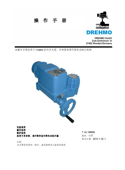
imatic电动执行器操作手册V1_17版
5
LEARN 模式......................................................................................................... 18
5.1 最重要的设定..................................................................................................................... 5.2 调整对比度........................................................................................................................ 5.3 如何设定语言..................................................................................................................... 5.4 LEARN 过程...................................................................................................................... 5.5 LEARN 菜单..................................................................................................................... 5.6 LEARN 过程最重要参数.................................................................................................... 5.7 LEARN 模式菜单结构和参数.............................................................................................
MICRO SWITCH GLS全球微型限位开关系列数据手册说明书
GLDB01C GLCB-01A4J GLCB01E7B GLCA01C GLCB-01A1B GLCB-01A2B GLDB01C GLCA05A1A GLCB01D GLEA01A4JMICRO SWITCH™ GLS Global Miniature (EN50047) Limit Switches Datasheet2What makes our switches better?Meets EN50047 mounting standards and EN/IEC electricalstandards for world-wide use Large existing install base and channel allows for quick deliveryworldwide Wide range of actuators and circuitry options in same footprint Certified for global use with CCC, CSA, CE, and UL acceptanceMICRO SWITCH™ GLS Miniature (EN50047 Style) Limit SwitchesThe Honeywell MICRO SWITCH™ GLS miniature limit switch family offers a wide range of products for global solutions. These durable and reliable limit switches are suitable for many industrial applications, agriculture equipment, transportation equipment, and other applications requiring an environmentally sealed (IP and NEMA) switch.The compact housings are often ideal for equipment where space is at a premium. The extensive product range is available in three different housing types; metal housing, plastic housing or a three conduit metal housing which are mounting compatible to EN50047. A wide range of actuators, contact blocks, and conduit/connectivity options enhance the product offering.In today’s demanding age of logic-level controls, electromechanical switches are frequently used to interface with PLCs and other logic level devices. GLS limit switches offer an option for gold-plated contacts for the standard switch. This option promotes the switch reliability for logic-level applications.EASY TO INSTALL AND MAINTAIN • GLOBAL RUGGED CONSTRUCTION • BUILT TO FITMiniature global limit switchwith heavy-duty ratings.Features and Benefits HOUSING MATERIAL OPTIONSMICRO SWITCH™ GLS limit switches are manufactured with either a metal housing or double-insulated plastic housing for indoor and outdoor applications.FLEXIBLE OPERATING HEADSFull range of actuator heads can be positioned at 90° increments for design flexibility. Side rotary actuator heads can be factory set for CW, CCW, or CW and CCW actuation to meet application requirements.BUILT FOR LONG LIFEDual bearing design on side rotary actuators reduces side loading and enhances mechanical life.CIRCUITRY OPTIONSWide variety of normally closed and normally open double-break snap-actionor slow-action contact options are available with silver contacts for power switching or gold-plated contacts for low energy loads.CIRCUIT FLEXIBILITYNormally closed double break direct opening contactsconform toEN/IEC 60947-5-1-3 to provide forced opening of the normally closed contact. Each contact throw is electrically isolated to accept different voltages (Form Zb contacts) which provides circuit flexibility. Double pole double throw (2NC/2NO) contact option require same polarity for each pole. (Form Za for each pole).LOW TEMPERATURE FOR SEVERE ENVIRONMENTS-40 °C [-40 °F] standard construction for side rotary and plunger actuated switches are suitable for many severe outdoor environments.GLOBAL ACCEPTANCEWith sealing up to IP66 and NEMA 4 for hostile environments, MICRO SWITCH™ GLS Series switches also carry CE, UL, CSA, CCC certification forglobal use.Galvanically isolated contacts for controllingtwo separate circuits.Removable contact block for wiring ease.34PASSENGER ELEVATORSBuffer actuation, top stop, floor detectionCOMMERICAL APPLIANCESDoor interlock switchESCALATORS/MOVING STAIRSSide skirt detection, loose or missing tread, comb detectionSCISSOR/PLATFORM LIFTSPothole detection, outrigger position, boom extend/retractMATERIAL HANDLINGOverhead doorsMACHINE TOOL EQUIPMENTPart presence, machine slide/table position, panel and door presenceOFF-ROAD EQUIPMENT• Agriculture planting and tillage equipment, stow position• Road construction equipment, panel & door interlock switches • Rail passenger door interlock switch •Position of motorized railroad switchPotential Applications5MICRO SWITCH™ GLS Global Miniature (EN50047 Style) Limit SwitchesMICRO SWITCH™ GLS SERIES PRODUCT NOMENCLATUREGLSwitch TypeA1AHead/ActuatorBodyCNOTE: not all combinations of model codes are available.Please contact your Honeywell provider/representative for assistance.ConduitAGLS Series Global Limit SwitchL01Basic SwitchModification CodesFor Actuator types beginning with A**For Type A modification codes,more than one code may be permissible. For example,GLCA01A1B-13 is a side rotary,lever-actuated switch,GLCA01A1B, adjusted for clock-wise actuation only. The operating shaft is to the right side of the switch when viewing the switch from the front (label side).6GLS SeriesTable 2. Electrical RatingsIEC 60947-5-1 (EN60947-5-1) AC 15, A300; DC 13, Q3007MICRO SWITCH™ GLS Global Miniature (EN50047 Style) Limit SwitchesMICRO SWITCH™ GLC SERIES ORDER GUIDE/RECOMMENDED LISTINGSFor listings not shown, contact your Honeywell representative.1Contact closed n ; Contact open o . *Positive opening occurs.1Contact closed n ; Contact open o . *Positive opening occurs.Table 5. Side Rotary Adjustable, Plastic Roller1Contact closed n ; Contact open o . *Positive opening occurs.8GLS Series1Contact closed n ; Contact open o . *Positive opening occurs.Table 7. Side Rotary Adjustable, Metal Rod, A4J (140 mm rod) and A4L (200 mm rod)1Contact closed n ; Contact open o . *Positive opening occurs.1Contact closed n ; Contact open o . *Positive opening occurs.MICRO SWITCH™ GLC SERIES ORDER GUIDE/RECOMMENDED LISTINGSFor listings not shown, contact your Honeywell representative.MICRO SWITCH™ GLS Global Miniature (EN50047 Style) Limit SwitchesMICRO SWITCH™ GLC SERIES ORDER GUIDE/RECOMMENDED LISTINGSFor listings not shown, contact your Honeywell representative.1Contact closed n ; Contact open o . *Positive opening occurs.Table 10. Top Pin Plunger110Table 12. Top Roller LeverMICRO SWITCH™ GLC SERIES ORDER GUIDE/RECOMMENDED LISTINGSFor listings not shown, contact your Honeywell representative.Figure 1. GLC Side Rotary • A1, A1A, A1B, and A1YFigure 2. GLC Side Rotary • A2, A2A, A2B, and A2YFigure 5. GLC Side Rotary • A9A1Contact closed n; Contact open o.117,2 mm [0.28 in]for 0.5-14 NPTconduit threads.7,2 mm [0.28 in] for 0.5-14 NPT conduit threads.7,2 mm [0.28 in] for0.5-14 NPT conduitthreads.Figure 10. GLC Wobble • K8A/K8B7,2 mm [0.28 in] for0.5-14 NPT conduitthreads.Figure 11. GLC ConduitFor listings not shown, contact your Honeywell representative.1Contact closed n; Contact open o. *Positive opening occurs.1Contact closed n; Contact open o. *Positive opening occurs.13For listings not shown, contact your Honeywell representative. Table 18. Side Rotary Adjustable, Plastic Roller1Contact closed n; Contact open o. *Positive opening occurs. **No roller1Contact closed n; Contact open o. *Positive opening occurs.For listings not shown, contact your Honeywell representative.1Contact closed n; Contact open o. *Positive opening occurs.1Contact closed n; Contact open o. *Positive opening occurs.1Contact closed n; Contact open o. *Positive opening occurs.1516Table 23. Side Rotary, 50 mm Rubber Roller1Contact closed n ; Contact open o . *Positive opening occurs.1Contact closed n ; Contact open o . *Positive opening occurs.MICRO SWITCH™ GLD SERIES ORDER GUIDE/RECOMMENDED LISTINGSFor listings not shown, contact your Honeywell representative.17MICRO SWITCH™ GLD SERIES ORDER GUIDE/RECOMMENDED LISTINGSFor listings not shown, contact your Honeywell representative.181Contact closed n ; Contact open o .MICRO SWITCH™ GLD SERIES ORDER GUIDE/RECOMMENDED LISTINGSFor listings not shown, contact your Honeywell representative.19Figure 13. GLD Side Rotary • A2, A2A, A2B, and A2YFigure 14. GLD Side Rotary Rod • A4J (140 mm) & A4L (200 mm)0.5-14 NPT conduitthreads.0.5-14 NPT conduitthreads.7,2 mm [0.28 in] for 0.5-14 NPT conduitthreads.MICRO SWITCH™ GLD DIMENSIONAL DRAWINGS mm [in]7,2 mm [0.28 in] for0.5-14 NPT conduit threads.Figure 21. GLD Wobble • K8A/K8BMICRO SWITCH™ GLD DIMENSIONAL DRAWINGS mm [in]1Contact closed n ; Contact open o . *Positive opening occurs. † 0.5-14 NPT conduit option includes adapter.Table 31. Side Rotary, Metal Roller1Contact closed n ; Contact open o . *Positive opening occurs. † 0.5-14 NPT conduit option includes adapter.MICRO SWITCH™ GLE SERIES ORDER GUIDE/RECOMMENDED LISTINGSFor listings not shown, contact your Honeywell representative.1Contact closed n ; Contact open o . *Positive opening occurs. † 0.5-14 NPT conduit option includes adapter.Table 33. Side Rotary Adjustable, Metal Roller1Contact closed n ; Contact open o . *Positive opening occurs.† 0.5-14 NPT conduit option includes adapter.MICRO SWITCH™ GLE SERIES ORDER GUIDE/RECOMMENDED LISTINGSFor listings not shown, contact your Honeywell representative.1Contact closed n ; Contact open o . *Positive opening occurs. † 0.5-14 NPT conduit option includes adapter.1Contact closed n ; Contact open o . *Positive opening occurs. † 0.5-14 NPT conduit option includes adapter.Table 37. Side Rotary Conveyor Lever, Ceramic Roller1Contact closed n ; Contact open o . *Positive opening occurs.MICRO SWITCH™ GLE SERIES ORDER GUIDE/RECOMMENDED LISTINGSFor listings not shown, contact your Honeywell representative.MICRO SWITCH™ GLE SERIES ORDER GUIDE/RECOMMENDED LISTINGS For listings not shown, contact your Honeywell representative.11Contact closed n ; Contact open o .MICRO SWITCH™ GLE SERIES ORDER GUIDE/RECOMMENDED LISTINGSFor listings not shown, contact your Honeywell representative.Figure 24. GLE Side Rotary • A2, A2A, A2B, and A2YFigure 25. GLE Side Rotary • A4J and A4LMICRO SWITCH™ GLE DIMENSIONAL DRAWINGS mm [in]Figure 31. GLE Wobble • E7BFigure 33. GLE Conduit Adapter for 0.5-14 NPT MICRO SWITCH™ GLE DIMENSIONAL DRAWINGS mm [in]REPLACEMENT PARTS - BASIC SWITCHESFACTORY PRE-WIRED LIMIT SWITCHES WITH INTEGRAL CONNECTORFACTORY PRE-WIRED LIMIT SWITCHES WITH INTEGRAL CONNECTOREpoxy coated metal Limit SwitchesGLCC01B-D1: Top pin plunger, 1NC/1NO snap action, with Deutsch DT style 4 pin connector GLCC01C-D1: Top roller plunger, 1NC/1NO snap action, with Deutsch DT style 4 pin connector GLCC06A1B-D1: Side rotary with metal roller, 2NC slow action, with Deutsch DT style 4 pin con-nectorPlastic Limit SwitchesGLDC01A1A-D1: Side rotary with plastic roller, 1NC/1NO snap action, with Deutsch DT style 4 pin connectorGLDC01A1B-D1: Side rotary with metal roller, 1NC/1NO snap ac-tion, with Deutsch DT style 4 pin connectorGLDC01C-D1: Top roller plunger, 1NC/1NO snap action, with Deutsch DT style 4 pin connectorNote: Reference base catalog listing for switch characteristics. For example, cat. listing GLCC01B-D1 has base cat. listing GLCC01B.Connector Without Limit SwitchGLZ8C-DEU : DT style 4 pin connector prewired with 6 in. of lead wires (4) and 20mm conduit thread with jam nutGLZ8C-PA : DT style 4 pin connector packet with all parts furnished unassembled for a 20 mm conduit threadGLCA01A1A GLCA01A1B GLCA01A1B-3GLCA01A2A GLCA01A2B GLCA01A4J GLCA01A5B GLCA01A9A GLCA01B GLCA01C GLCA01C-6GLCA01D GLCA01E7B GLCA01K8A GLCA01K8B GLCA03A1A GLCA03A1B GLCA03B GLCA03C GLCA03C-6GLCA03D GLCA03E7B GLCA03K8B GLCA04A1B GLCA04A2B GLCA04B GLCA05A1A GLCA06A1B-4GLCA06A5B GLCA06C-6GLCA06E7B GLCA07A1B-3GLCA36A5B GLCA36D GLCB01A1A GLCB01A1A/4GLCB01A1B GLCB01A2A GLCB01A2B GLCB01A4J GLCB01A4L GLCB01A5B GLCB01A9AThis datasheet supports the following MICRO SWITCH™ GLS Series Limit SwitchesGLCB01B GLCB01C GLCB01D GLCB01E7B GLCB01K8A GLCB01K8B GLCB03A1B GLCB03A2A GLCB03B GLCB03C GLCB03D GLCB04A1B GLCB04B GLCB04C GLCB04D GLCB06A1B GLCB06A1B-3GLCB06A1B-4GLCB06A2B GLCB06B GLCB06C GLCB07A1B GLCB07A1B-3GLCB07A2B GLCB07B GLCB07C GLCB07D GLCB07E7B GLCB33DGLCB34A1B-5GLCB35A1B-5GLCB36C GLCC01A1A GLCC01A1B GLCC01A2B GLCC01A4J GLCC01A9A GLCC01B GLCC01B-D1GLCC01C GLCC01C-D1GLCC01D GLCC01E7BGLCC03A2B GLCC06A1B-D1GLCC06C GLCC06D GLCC07A1A GLCC07A1B GLCC07A2B GLCD03A1A GLCD03B GLDA01A1A GLDA01A1A-D GLDA01A1B GLDA01A1B-D GLDA01A1Y GLDA01A2A GLDA01A2B GLDA01A2Y GLDA01A4J GLDA01A5B GLDA01A9A GLDA01B GLDA01C GLDA01C-D GLDA01D GLDA01E7B GLDA01K8B GLDA03A1A GLDA03A1B GLDA03A1Y GLDA03A2Y GLDA03A9A GLDA03B GLDA03C GLDA03C-6GLDA03D GLDA03E7B GLDA03K8B GLDA04A2B GLDA04A4J GLDA04B GLDA05A2B GLDA06A1B GLDA06A2AGLDA06A9A GLDA06C GLDA06D GLDA07A2B GLDA07A9A GLDA07C GLDB01A1-3GLDB01A1A GLDB01A1B GLDB01A1B3GLDB01A1Y GLDB01A2GLDB01A2A GLDB01A2B GLDB01A2Y GLDB01A4J GLDB01A5B GLDB01B GLDB01C GLDB01D GLDB01D-D GLDB01E7B GLDB01K8B GLDB03A1A GLDB03A1B GLDB03A1Y GLDB03A1Y-3GLDB03A1Y-4GLDB03A2A GLDB03A2Y GLDB03B GLDB03C GLDB03C-6GLDB03D GLDB04A1A GLDB04B GLDB04C GLDB04D GLDB06A1B GLDB06A2A GLDB06C GLDB07A1A GLDB07A1BGLDB07A2A GLDB07A2B GLDB07B GLDB07C GLDB33C GLDB33C-6GLDB36A5B GLDB36C GLDB36C-6GLDC01A1A GLDC01A1A-D1GLDC01A1B GLDC01A1B-D1GLDC01A1Y GLDC01A2A GLDC01A2B GLDC01A4J GLDC01A5B GLDC01A9A GLDC01B GLDC01C GLDC01C-D1GLDC01D GLDC01E7B GLDC01K8B GLDC03A4J GLDC03C GLDC03D GLDC04B GLDC05A1A GLDC05A2A GLDC05B GLDC05C GLDC05D GLDC06A1A GLDC06A1B GLDC06C GLDC06D GLDC07A1B GLDC07B GLDD01A1B GLDD01D GLEA01A1AGLEA01A1B GLEA01A2A GLEA01A2B GLEA01A4J GLEA01A5A GLEA01A5B GLEA01B GLEA01C GLEA01D GLEA01E7B GLEA06D GLEA24A1B GLEA24A1B-C GLEA24A2A GLEA24A2B GLEA24A4J GLEA24A5B GLEA24B GLEA24C GLEA24C-6GLEA24D GLEA24E7B GLEA32A1A GLEB01A1A GLEB01A1B GLEB01A2A GLEB01A2B GLEB01A4J GLEB01A5A GLEB01A5B GLEB01A9A GLEB01B GLEB01C GLEB01D GLEB01E7B GLEB01K8A GLEB03A5B GLEB03B GLEB04A1B GLEB06A1A GLEB07A1B GLEB07A2B GLEB07BGLEB07C GLEB07K8A GLEB24A1B GLEB24A2B GLEB24B GLEB24C GLEB24C-6GLEB24D GLEB24E7B GLEB24K8A GLEB32A1A GLEB33B GLEC01A1B GLEC01A2B GLEC01A4J GLEC01A9A GLEC01B GLEC01C GLEC01D GLEC03B GLEC24A1B GLEC24A2A GLEC24B GLEC24C GLEC24D GLEC32B GLEC33B GLED01D GLZ301GLZ303GLZ304GLZ306GLZ307GLZ332GLZ333GLZ334GLZ336GLZ8C-DEU GLZ8C-PAGLS SeriesADDITIONAL INFORMATIONThe following associated literature is available on the Honeywell web site at :• Product installation instructions• Aerospace range guide• Transportation range guide• Limits and Machine Safety range guide• Product application-specific information– Application Note: Sensors and Switches for Industrial ManualProcess Valves– Application Note: Sensors and Switches Used in ValveActuators and Valve Positioners– Industrial Machinery Switch Guide– Limit and Enclosed Switches Application Information– Limit and Enclosed Switches Operating Characteristics – Limit and Enclosed Switches Reference Standards– Limit and Enclosed Switches Typical Applications– Sensors and Switches in Mobile Cranes– Sensors and Switches in Front Loaders– Sensors and Switches in Elevator ApplicationsWARRANTY/REMEDYHoneywell warrants goods of its manufacture as being free of defective materials and faulty workmanship. Honeywell’s standard product warranty applies unless agreed to otherwise by Honeywell in writing; please refer to your order acknowledgement or consult your local sales office for specific warranty details. If warranted goods are returned to Honeywell during the period of coverage, Honeywell will repair or replace, at its option, without charge those items it finds defective. The foregoing is buyer’s sole remedy and is in lieu of all other warranties, expressed or implied, including those of merchantability and fitness for a particu-lar purpose. In no event shall Honeywell be liable for conse-quential, special, or indirect damages.While we provide application assistance personally, through our literature and the Honeywell website, it is up to the customer to determine the suitability of the product in the application. Specifications may change without notice. The information we supply is believed to be accurate and reliable as of this printing. However, we assume no responsibility for its use.107147-14-EN IL50 GLO July 2014Copyright © 2014 Honeywell International Inc. All rights reserved.Sensing and Control Honeywell1985 Douglas Drive North Golden Valley, MN 55422 Find out moreHoneywell serves its customers through a worldwide network of sales offices, representatives and distributors. For application assistance, current specifications, pricing or name of the nearest Authorized Distributor, contact your local sales office.To learn more about Honeywell’s sensing and control products, call +1-815-235-6847 or 1-800-537-6945,visit , or e-mail inquiries to *********************GLEB01A1B GLEB24B GLDB01A2AGLDB01C GLCB-01A4J GLCB01E7B GLCA01C GLCB-01A1B GLCB-01A2B GLDB01C GLCA05A1A GLCB01D GLEA01A4J。
限位开关说明书(堵煤开关)
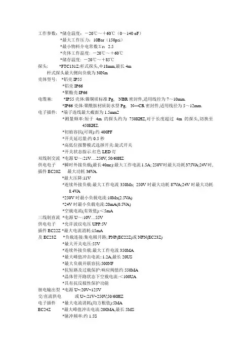
工作参数:*储仓温度:-20℃~+60℃(0~140 oF)*最大工作压力:10Bar(150psi)*最小物料介电常数Σr:2.5*壳体工作温度: -20℃~+60℃*储存温度: -20℃~+85℃探头: *FTC131Z:杆式探头,Φ18mm,最长4m杆式探头最大侧向负载为30Nm壳体型号: *铝壳IP55*铝壳IP66*聚酯壳:IP66电缆塞: *IP55壳体:镍铜质标准Pg, NBR密封件,适用线径为7~10mm.*IP66壳体:聚酰胺材质防水型Pg, N—CR密封件,适用线径为5~12mm.电子插件: *端子连线最大截面为1.5mm2*测量频率:短于4m的探头约为750KHZ,对于长度超过4m的探头,切换至450KHZ.*初始容抗(可调):约400PF*开关延迟量:约0.5秒*高低位报警模式选择开关:旋式开关*开关状态指示.红色LED灯双线制交流*电源U~:21V….250V, 50/60HZ供电电子*瞬时外接负载(最长40ms):最大工作电流1.5A; 250V时最大功耗375V A;24V时, 插件EC20Z 最大功耗36V A.*最大压降:11V*连续外接负载:最大工作电流350Ma; 250V时最大功耗87V A;24V时最大功耗8.4V A*250V时最小负载电流:10Ma(2.5V A)*24V时最小负载电流:20mA(0.5V A)*空载电流(有效值):<5mA三线制直流*电源U~:10V (55V)供电电子*允许波纹电压UPP:5V插件EC22Z *最大电流消耗:15mA及EC23Z *负载连接:集电极开路; PNP(EC22Z)或NPN(EC23Z)*最大开关电压:55V*连续外接负载:最大工作电流350MA*最大峰值冲击电流::1.2A,最长20US*最大负载并联容抗:500NF*抗短路及过载保护:响应阀值约550MA*晶体管开路状态下空载电流:<100UA*具有抗反极性保护功能继电输出型*电源U~:20V~125V交/直流供电或U~:21V~250V,50/60HZ电子插件*最大电流消耗(均方根值):5MAEC24Z *最大峰值冲击电流:200MA,最长5MS*脉冲频率:约1.5S*输出:无源翻转触点器*触点器负载能力:U~最大为250V,I~最大为4AP~最大为1000V A(COSφ=1)或P~最大为350V A,COSφ>=0.7U~最大为100V,I~最大为100W*工作寿命:最大接触负载下,至少可工作十万次*外加翻转延迟:最大1.5S测量系统整个系统是由下列部分组成:1NIVOCOMPACT FTI2电源3用户后接控制系统,开关,信号变送器(如过程控制系统,PLC,继电器,微型触点器,灯,喇叭等).工作原理探头于储仓的侧壁作为两个相对的电极组成一个电容器,而此电容器则被施以一个高频电场.基於放电回路的工作原理而获得具体物位值:当探头位于介电数εR为1的大气中时,放电时间常数τ=R.CA,其中R为电路的阻抗.而CA为探头与器壁所组成电容器的容抗.若具有较高介电常数的物料进入电场区域,则容抗值CA增大,时间常数τ亦随之增大.上述时间长数的变化量被读出,NIVOCOMPACT根据一定的开关工作模式被触发只要物料在探头与仓壁或仓顶之间不行成导通桥路,NIVOCOMPACT就具有很强的抗物料积垢能力.内置的最低/最高位报警模式选择功能保证NIVOCOMPACT所具有很高的操作安全性要求的应用场合以静态电流方式工作.高位报警模式:探头被浸没或电源出现故障时,电路断开.低位报警模式:当探头与被测物料脱离或电源出现故障时,电路断开.位于电子插件上的红色LED显示灯开关状态.应用范围FTC131Z主要用来对小型储仓中细粒散料进行限位探测.FTC331Z用来对大型储仓中细粒或粗粒散料进行限位探测.若储仓中盛放很大颗粒或磨损性很强的物料,NIVOCOMPACTFTC331Z只能用来实现高限位探测.探头之间距离为避免探头之间的相互干扰,不同探头之间应保证至少0.5M的间距位于相邻的由非导电材料组成的储仓中的探头之间亦应保证起码0.5M的距离利用气动式加料机对储仓加料时,探头之间距应更大一些,这样,即使探头晃动,亦能保证其相互间最小间距之要求.储仓加料加料物流应避免直接指向探头.室外安装作为附件供用户选用的全天候保护罩对铝壳结构的Nivocompact开关起到防过热及冷凝之作用.一般而言,大幅度的温度变化极易引起冷凝现象.电气连线(接线)各种不同电子插件的主要特性: 位于产品标牌上的定购代码中的最后一位数字代表位于Nivocompact FTC开关中电子插件的型号:1=电子插件EC20Z双线制交流供电21V (250V)电子开关,最大电流350mA2=电子插件EC22Z三线制直流供电10V (55V)晶体管电路,负载连接PNP,最大电流350mA3=电子插件EC23Z三线制直流供电10V (55V)晶体管电路,负载连接NPN,最大电流350mA4=电子插件EC24Z无源继电输出交流供电21V...250V或直流供电20V (125V)负载极限: 注意与Nivocompact所连负载的极限值超出负载极限会损害或彻底损坏电子插件线径: 工作电流很小,故只需要小线径的电缆建议使用线截面为0.5~1.5mm2的普通电缆接地,与大地等势:必须保证Nivocompact的良好接地性,使其工作可靠,免受外界干扰可将Nivocompact与接地的金属或钢筋型罐壁相连,或将它与大地等势体PE 相连.若在塑料质储仓中已设反极板,则必须在Nivocompact与此反极板之间用一根短线进行接地连接.建立一个等势面势(与大地等势,接地)须严格遵循所有防爆规定.当电子插件安装与Nivocompact中时,自动满足设计认可证书中(A7)1及2所有专门要求/指标.双线制交流供电电子插件EC20Z的连线: 正象所有开关一样,带电子插件EC20Z的物位开关Nivocompact必须与负载(如继电器,微触点器,灯泡等)串接与电源上.在没有任何中介负载情形下,将开关与电源直接相连(短路)会引起迅速而永久的电子插件损坏.负载可串接与电子插件端子1或2的认一端L1亦可与端子1或2的任一端相连.电源电压: 电子插件接线端子1与2之间的端电压值不得低于21V ,电源的端压要稍高于21V,以不偿负载引起的压降.负载开路: 值得注意的是,位报警状态下, Nivocompact的电子插件中的电子开关断路,但此时与之串接的负载并未真正与电源脱开.由于电子插件本身的工作电流要求,此时一个很小的”空载电流”依然流过负载.若负载正好是一只保持电流很小的继电器时,继电器有可能拒绝释放,此时应在继电器两端并接一个负载,如电位器,信号灯等.保险丝: 确保保险丝的功率因子与最大外接负载相匹配.此细径保险丝对电子插件EC20Z不起保护作用三线制直流供电的电子插件EC22Z(PNP)的连线负载受控与晶体管: 接与端子3的负载受控与一只晶体管,类属非接触控制,不会发生返跳现象.正常开关状态下,端子3电位为正物位报警或电源发生故障时,晶体管开路.抗短路保护: 位与端子1与3之间的负载电路具有抗过载及短路能力(脉冲过载保护).过载或短路时,晶体管开路.抗峰压保护: 与强感应仪表相连时,必须接入一只限压器.三线制直流供电的电子插件EC23Z(NPN)的连接负载受控子晶体管电路: 接与端子3的负载受控与一只晶体管,类属非接触控制,故不会发生返跳现象.正常开关状态下,端子3电位为负.物位报警或电源发生故障时,晶体管开路.抗短路保护: 位与端子2和3之间的负载电路具有抗过载及短路的能力(脉冲过载保护) 过载或短路情形下,晶体管开路.抗峰压保护; 与强感应仪表相连时,应接入一只限压器.交/直流供电的电子插件EC24Z的连线电源: 交流供电,L1或N任一端皆可与端子1相连直流供电,L+或L-任一端皆可与端子1相连.服务于负载的继电触点器: 通过一只无源继电触点器(翻转触点器)实现负载的连接,物位报警或电源发生故障时,继电触点器触发,使端子3与4之间短路.抗峰压及短路保护: 在强感应仪表上接入一只火花压制器,用来保护继电触点器.发生短路现象时,细径保险丝F2(功率因子取决于负载大小)可对继电触点器起到保护作用.标定工具准备*齿宽3MM的螺丝刀*齿宽5MM的螺丝刀旋式开关及其他标定过程中所涉调节元件均位于壳体中电子插件上.紧挨标定元件的是电源输入端子,其上电压最大可达250V只允许使用除齿部之外全绝缘的螺丝刀,否则在进行标定之前,必须在电源输入端子上贴上绝缘胶带.容抗标定进行容抗标定时,储仓必须空仓或物位低於探头起码200MM●接通电源●按图23至25的次序进行标定●标定过程中避免水气进入壳体当探头表面被非导电,低介电常数的=固体散料覆盖时,只有当纵向安装探头的一段或横向安装的全部被物料浸没时,NIVOCOMPACT开关才会被触发探头的被覆盖程度取决于於标定工程.反向旋转微标元件,可使NIVOCOMPACT的反应稍许迟钝一些.限位报警模式利用旋式开关,用户可根据实际需要选择合适的限位报警模式*高位报警模式: 探头被物料浸没或电源发生故障时,电流回路开路*低位报警模式:探头裸露於大气中或电源发生故障时,电源回路开路. 功能测试探头裸露於大气中时,用一只带有绝缘柄的螺丝刀接触电子插件的中央紧固螺母,模拟固体散料浸没探头的情形.此时,LED灯的显示状态翻转上述过程仅可用来对仪表的功能控制性能进行测试只有通过现场加料或空仓作业才能真正检查仪表的限位探测功能是否正常.试验过程中物位应:_与侧向安装杆式探头的安装点等高_与纵向安装杆式探头杆端点位置等高_与缆式探头的重锤位置等高!故障排除出现故障时,首先应检查确认*NIVOCOMPACT连接正常*与储仓或反极板接地良好*电源供电正常*所有相连仪表工作正常*使用EC20Z插件时,对相连仪表的最小负载;量要求得到满足*限位报警模式选择正确*标定正确.。
KISSLING G13限位开关说明书
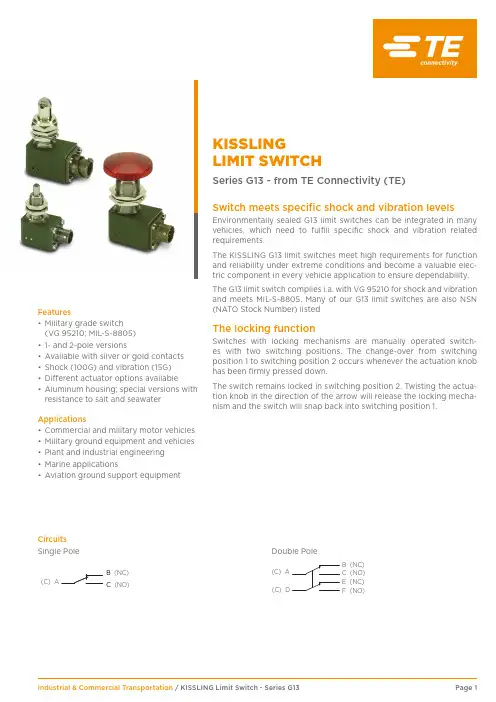
KISSLINGLIMIT SWITCHSeries G13 - from TE Connectivity (TE)Switch meets specific shock and vibration levelsEnvironmentally sealed G13 limit switches can be integrated in many vehicles, which need to fulfill specific shock and vibration related requirements.The KISSLING G13 limit switches meet high requirements for function and reliability under extreme conditions and become a valuable elec-tric component in every vehicle application to ensure dependability.The G13 limit switch complies i.a. with VG 95210 for shock and vibration and meets MIL-S-8805. Many of our G13 limit switches are also NSN (NATO Stock Number) listedThe locking functionSwitches with locking mechanisms are manually operated switch-es with two switching positions. The change-over from switching position 1 to switching position 2 occurs whenever the actuation knob has been firmly pressed down.The switch remains locked in switching position 2. Twisting the actua-tion knob in the direction of the arrow will release the locking mecha-nism and the switch will snap back into switching position 1.Features• Military grade switch (VG 95210; MIL-S-8805)• 1- and 2-pole versions• Available with silver or gold contacts • Shock (100G) and vibration (15G) • Different actuator options available• Aluminum housing; special versions with resistance to salt and seawaterApplications• Commercial and military motor vehicles • Military ground equipment and vehicles • Plant and industrial engineering • Marine applications•Aviation ground support equipmentCircuits BC (C) AB (NC)C (NO)F (NO)E (NC)(C) D(C) A B (NC)C (NO)Single PoleDouble PoleSpecificationTechnical DataHousing Material | Special type AI-alloy | salt- and seawater resistance Temperature range | Special type -55°C to +85°C | -55°C to +125°C Protection (connected)IEC 60529, IP67 (0,2 bar, 5min)Vibration i.a.w. MIL-STD-202;Method 204; Test condition B (10-2000 Hz)15g Shock i.a.w. MIL-STD-202;Method 213; Test condition I (6 ms; sawtooth)100g Insulation resistance i.a.w MIL-STD-202;Method 302; Test condition B (500 V; 1 min)min. 100 M ΩDielectric withstanding voltage i.a.w MIL-STD-202; Method 3011050VACmax. approach speed at an angle of <30°Ball, Dome Roller5m/min 30m/min Operating force without looking 15 or 30 ± 5 N Operating force with lookingapprox. 60 ± 5 N Endurance without lookingi.a.w. MIL -S-8805; §4.8.26 (28 VDC; 1 Amps)i.a.w. MIL -S-8805; §4.8.26 (28 VDC; 5 Amps)only silver contacts100.000 cycles 25.000 cyclesEndurance with lookingi.a.w. MIL -S-8805; §4.8.26 (28 VDC; 5 Amps)only silver contacts mecanical10.000 cycles 10.000 cyclesSwitch inserts TypeMS 24547-1 / silverMS 24547-2 / goldi.a.w. MIL-S-8805up to +82°C up to +82°C Electrical rating max.min.max.min.Resistive load 28VDC, 7A 15VDC, 10mA 28VDC, 1A 15VDC, 5mA inductive load 28VDC, 7A5VDC, 20mA28VDC, 0.5A5VDC, 10mAMounting dimensions M20x1M16x1M12x1Mounting hole: with locking ringTechnical drawingsSWITCH WITH LOCKING MECHANISMExampleG13-01-1183 (SILVER)G13-01-1641 (GOLD)Example G13-01-1550 (GOLD)Example G13-01-1167 (SILVER)Example G13-01-1689 (SILVER)Example G13-01-1133 (SILVER)ExampleG13-01-1220 (2-POLE, SILVER, RED)G13-01-1629 (2-POLE, GOLD, RED)G13-01-1585 (2-POLE, SILVER, GREEN)G13-01-1470 (WITH CONNECTOR CECC 75201, RESISTANT TO SALTWATER)ExampleG13-01-1097 (1-POLE, SILVER)ExampleG13-01-1365 (2-POLE, SILVER)Housing dimension miniHousing dimension smallHousing dimension largeTE Connectivity, TE, TE connectivity (logo) and KISSLING (word) are trademarks owned or licensed by the TE Connectivity family of companies. All other logos, products and/or company names referred to herein might be trademarks of their respective owners.The information given herein, including drawings, illustrations and schematics which are intended for illustration purposes only, is believed to be reliable. However, TE Connectivity makes no warranties as to its accuracy or completeness and disclaims any liability in connection with its use. TE Connectivity‘s obligations shall only be as set forth in TE Connectivity‘s Standard Terms and Conditions of Sale for this product and in no case will TE Connectivity be liable for any incidental, indirect or consequential damages arising out of the sale, resale, use or misuse of the product. Users of TE Connectivity products should make their own evaluation to determine the suitability of each such product for the specific application.© 2020 TE Connectivity | All Rights Reserved. K1166743 | Version 08/2020Available typesHousing dimensions ActuatorLength of thread mm Mounting thread Width across flats Switch inserts Connector (Standard)cable (option)mini Dome Roller 14 - 18M12SW17single poleH8-3APN VG 95328/MIL-C-26482smallBall Dome Manual18 - 36M12SW17single poleH8-3APN VG 95328/MIL-C-26482largeBall Ball RollerManual with lock-ing mechanism red, green, black14 - 3618 - 3014 - 30 30M12M16M16M20SW17SW22SW22SW27single or double poleA10-SL-3PN VG 95234A10-98PN VG 96912C10-6PN VG 95328/MIL-C-26482MIL-C-D38999。
限位开关说明安装及设置

■限位开关的概念限位开关,指为保护内置微动开关免受外力、水、油、气体和尘埃等的损害,而组装在外壳内的开关,尤其适用于对机械强度和环境适应性有特殊要求的地方。
形状大致分为横向型、竖向型和复合型。
下图表示典型的竖向型限位开关的构造。
限位开关大致上是由五个构成要素组成的。
■内置微动开关驱动机构对于限位开关来说,微动开关的驱动机构是与密封性能和动作特性直接相关的重要部分。
其构造分为三类,如下表所示。
(1)活塞型根据密封方法不同,有表中的A型和B型2个种类。
A型是用O型环或薄膜密封的,由于密封橡胶没有外露,在抵制工作机械的切割碎屑方面功能较强大,但其反面影响是,有可能会将砂子、切割粉末等压入活塞的滑动面。
B型虽然不会把砂子、切割粉末等压入,且密封性能优于A型,但由于炽热的切割碎屑飞溅过来,有可能会损坏橡胶帽。
因此,要根据使用场所的不同选用A型或B型。
而柱塞型仍然通过柱塞的往复运动压缩或吸进空气。
为此,如果长时间将柱塞压入,限位开关内的压缩空气逸失,内部压力将与大气压相同,即使急于让柱塞复位,柱塞却有迟缓复位的倾向。
为了避免发生这种故障,设计时,根据柱塞的压入将空气的压缩量控制在限位开关内部全部空气量的20%以内。
另外,为了延长微动开关的寿命,在这一构造内部设置了一个OT吸收机构,该OT吸收机构采用OT吸收弹簧,用以吸收残余的柱塞的行程。
该机构相对于柱塞的运动,在中途停止按压微动开关辅助柱塞的行程。
(2)铰链摆杆型在摆杆端部(滚珠),柱塞的行程量根据摆杆的比例扩大,因此,一般不使用OT吸收机构。
(3)旋转摆杆型举一个典型的示例,来示例WL的构造,但除此之外,还有两个类型:将复位柱塞的功能赋予柱塞的类型;通过线圈弹簧获取复位力、用凸轮带动辅助柱塞的类型。
■开关的构成材料开关的主要部分是由下列材料构成的限位开关用语说明限位开关:为保护小型开关不受外力、水、油、尘埃等的侵害而将其装入金属外壳或者塑料外壳中的开关。
APL系列限位开关说明书
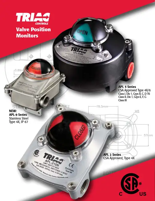
L I M I T S W I T C H E S1APL 2 SeriesCSA Approved, Type 4XValve Position MonitorsAPL 5 SeriesCSA Approved Type 4X/6Class I, Div 1, Grps B, C, D T6Class II, Div 1, Grps E, F , G Class IIICUSNEW:APL-9 Series Stainless Steel Type 4X, IP 67T riac ®APL Series Limit Switches The Triac APL Series Limit Switches feature high quality, easy to use multiple option switch boxes for rotary actuators. Their die cast aluminum housings are powder coated for corrosion resistance and feature red/ green visual indicators, quick-set cams and easy access terminal strips. These economical switch boxes offer numerous switch, sensor and transmitter options to handle most applications found in today’s process• Solid and compact design• Dome visual indicator (3-way available)• Dual 1/2” NPT conduit entries, 8 pts. on terminal strip • Quick-set spring loaded cam• Captive cover bolts• NAMUR low profile brackets• Available Switches 10, 18, 20 & 23• Ambient temperature range -20°C to 80°C (-4°F to 176°F)APL-210APL-218Simple device for intrinsicallysafe applicationsC US262375NEW: APL-9 Series Stainless SteelType 4X, IP 67304 Stainless Steel enclosureStainless Steel shaft & captive cover boltsDome visual indicatorDual 1/2” NPT conduit entries, 8 pts. on terminal stripQuick-set spring loaded camNAMUR stainless steel bracketMultiple options - up to four switches, intrinsically safe,reed type sensors (See options 12, 20, and 30 on page 7)Ambient temperature range -20°C to 80°C (-4°F to 176°F)2L I M I T S W I T C H E S3APL-3 SeriesAPL-4 SeriesAPL-5 Series• CSA Approved, Type 4X• Die-cast aluminum powder coated enclosure• Rugged and flexible design• Dome visual indicator (3-way available)• Dual 1/2” NPT conduit entries, 8 pts. on terminal strip • Quick-set spring loaded cam • Captive cover bolts • NAMUR brackets• Multiple options - up to four switches, various mechanical, proximity and reed type sensors, feedback potentiometers and 4-20mA transmittersAmbient temperature range -20°C to 80°C (-4°F to 176°F)CSA Approved, Class I, Division 1, Groups C & D T6 Class I, Zone 1, AEx d IIB, T6, Ex d IIB, T6, Type 4X/6, IP 66/67/68ATEX/IECEx rating available: Ex d IIB T6 Gb(*Use ATEX suffix to denote this option. Ex: APL-410N-ATEX)• Dome visual indicator (3-way available)• Dual 3/4” NPT conduit entries, 8 pts. on terminal strip Quick-set spring loaded cam Captive cover bolts NAMUR bracketsMultiple options - up to four switches, various mechanical, proximity and reed type sensors, feedback potentiometers and 4-20mA transmittersAmbient temperature range -20°C to 60°C (-4°F to 140°F)•CSA Approved: Type 4X/6, IP 66/67Class I, Division 1, Group B, C & D T6; Class II, Division 1, Group E, F, G; Class III Class I, Zone 1, AEx d IIC, T6;Class II, Zone 21, AEx tb IIIC T65°C DbEx d IIC, T6; Ex tb T65°C DbATEX/IECEx rating available:Ex d IIC T6 Gb; Ex tb IIIC T85°C Db, IP67(*Use ATEX suffix to denote this option. Ex: APL-510N-ATEX)Dome visual indicator (3-way available)Dual 3/4” NPT conduit entries, 8 pts. on terminal strip Quick-set spring loaded camScrew on enclosure lid with spring loaded cover bolts - unique design to hold bolts inside cover NAMUR bracketsproximity and reed type sensors, feedback potentiometers and 4-20mA transmitters• Ambient temperature range -20°C to 60°C (-4°F to 140°F)•Low temp option down to -50°C (-58°F) with C1, C3 switches onlyC US 262375C US 262375CUS2623754APL-2 SeriesAPL-3 SeriesAPL-4 SeriesAPL-5 SeriesL I M I T S W I T C H E S5(2) DPDT SWITCHES(2) SPDT SWITCHES 5K OHM POTENTIOMETER(2) SPDT SWITCHES 4-20mA TRANSMITTER (2) P&F NJ2-V3-N SOLID STATE SENSORS12GROUND5349786121110RED BLACK NCWHITE BROWN YELLOW C BLUE RED BLACK NONC CNC NO WHITE BROWN NOC NCNOYELLOW TOP SWITCHSWITCHBOTTOM CBLUE OPENCLOSE 13EXT14VALVESOLENOID 3CLOSE12BLUE YELLOW RED BLACK NC NO COPEN56798WHITE BROWNCNO123GROUNDNC 4TOP SWITCHSWITCHBOTTOM POTENTIOMETER111210VALVESOLENOID EXTR-I CONVERTERGROUND12VALVESOLENOID CCNONONC 321SWITCHBOTTOM POTENTIOMETER-+1CLOSE RED BLACK BLUE OPENBROWNWHITE YELLOW NCSWITCHTOP 658971110342+-BROWNBLUESWITCH MODEL:NJ2-V3-N-V5TYPE:PROXIMITY SWITCHS VOLTAGE: 5V--30V DCNOTEGROUNDWiring Schematics(2) SPDT SWITCHESNCNO CBOTTOM SWITCHGREENNOREDNCTOP SWITCHCLOSE BLACK OPEN BROWNGROUND7EXT86YELLOW BLUE WHITE C5423VALVESOLENOID RED 1(4) SPDT SWITCHES12GROUND5349786121110RED BLACK NCWHITE BROWN YELLOW C BLUE RED BLACK NONC CNC NOWHITE BROWN NOCNC NO YELLOW CBLUE BOTTOM SWITCHGREENREDGREENREDTOP SWITCHCLOSEOPEN CLOSE OPEN 13EXT14VALVESOLENOIDSolenoid Valve Integration:APL-5 Series & ASCO Solenoid3-Way Solenoid+EF8320G184+EV8320G202+EV8316G381V-D244-Way Solenoid+EF8342G001+EV8342G701Triac Cobra Limit Switches:The Triac Cobra hermetically sealed proximity switcheshave a patent pending design for high (C1) and low(C3) current applications. This design has the currentcapability of a mechanical switch with the reliability ofsolid state sensors with up to 10,000,000 cycles.We recommend using our Cobra C3 (Gold Bifurcated)limit switch for low current and intrinsically safeapplications.C1 HermeticallySealed Proximity Switch Silver Oxide SPDT Contacts Contact Rating5 A resistive, 3 A inductive, 28VDC 5 A resistive or inductive. 250VAC C3 HermeticallySealed Proximity SwitchGold Bifurcated SPDT Contacts Contact Rating1 A resistive, 0.5 A inductive, 28VDC 1 A resistive or inductive. 125VACNOTES: • entry must be closed with appropriate conduit plug.†is required during installation.8TriacEX Series Limit Switches The TriacEX Series hazardous location Limit Switch provides a compact design and low cost for both visual and remote electrical indication of rotary valve/actuator position. The heavy duty design and wide variety of options make the EX Series the ideal multi-purpose Limit Switch for use in NEMA 4, 4X, 7 and 9 applications.Features:• Aluminum Housing: Polyester Powder Coating• Twin Shaft Body Design: The primary shaft is located in the housing base and connects to a mating shaft located in the housing cover. This twin shaft feature allows easy and accurate housingassembly by eliminating the blind-hole configuration associated with competitive switch boxes.• Multiple Switch Options: Wide variety of mechanical, proximity and inductive switch options provide the most effective andeconomical choice for each specific application.• Visual Position Indication: The 3D rotor provides high visibility confirmation of valve/actuator position. The splined retainer allows adjustment to coincide with the exact valve position.• “Easy-Set” Cams: Splined, spring loaded and independently adjustable. This design offers tool-free calibration and positivevibration resistant engagement.• Multiple Cable Entries: Standard with two ½” NPT cable entries with option for third ½” or ¾” NPT cable entry.• Standardized Mounting: ISO F05 mounting pattern and VDI/ VDE3845 shaft• Options: AS-i digital communication interface card, 3-position dribble control, 4-20mA feedback transmitter, special terminal strips,NAMUR mounting brackets.L I MIT S W I T C H E S9Triac : UL Listed and Explosion Proof Limit Switches• Available in Aluminum (EC) or 316SST (ES)Housing• UL Listed NEMA 4, 4X, Weather Proof • Visual indicator options• Dual threaded conduit entries with extra terminals • High Resolution Splined Cam• Temperature Range: -40˚F (-40˚C) to 176˚F (80˚C)• ISO F05 mounting pattern and VDI/VDE3845 shaft Available with 3-way Pneumatic valveMultiple options - up to three switches, variousmechanical, proximity and reed type sensors,feedback potentiometers and 4-20mA transmitters, AS-i interface• Low Copper Aluminum Housing• UL Listed NEMA 4, 4X, 7 & 9, Explosion Proof & Weather ProofClass I, Division 1, Groups B, C & D Class II, Division 1, Groups E, F & G • Visual indicator with twin shaft design• Up to four conduit entries with extra terminal options • High Resolution Splined Cam• Temperature Range: -40˚F (-40˚C) to 176˚F (80˚C) (T6)• Low Temperature rating down to -76˚F (-60˚C) available onrequest (available with 1D Switch option only)• ISO F05 mounting pattern and VDI/VDE3845 shaft• Multiple options - up to six switches, various mechanical,proximity and reed type sensors, feedback potentiometers and 4-20mA transmitters• 316 Stainless Steel Housing• UL Listed NEMA 4, 4X, 7 & 9, Explosion Proof & Weather ProofClass I, Division 1, Groups B, C & D Class II, Division 1, Groups E, F & G• Visual indicator options with twin shaft design• Up to four conduit entries with extra terminal options • High Resolution Splined Cam• Temperature Range: -40˚F (-40˚C) to 176˚F (80˚C) (T6)• request (available with 1D Switch option only)• ISO F05 mounting pattern and VDI/VDE3845 shaft • Multiple options - up to six switches, variousmechanical, proximity and reed type sensors, feedback potentiometers and 4-20mA transmittersEY SeriesEW SeriesEC/ES Series10How To OrderUL Listed and Explosion Proof Limit SwitchesNOTES:*Gold plated switches are suitable for intrinsically safe applictions and also hazardous locations.*Conduit plugs supplied with the switch box are for transit purposes only. To ensure Type 4, 4X, 7 & 9 protection, any unused conduit entry must be closed with appropriate conduit plug.NOTE #1:EX series has the following approval:• Enclosure Approvals: UL and cUL, Type 4, 4X, 7 & 9, (ML FILE NO. E236166)• Class I, Division 1 Groups C & D • Class II, Division 1, Groups E, F & G NOTE #2:EY & EW series have the following approval:• Enclosure Approvals: UL and cUL, Type 4, 4X, 7 & 9, (ML FILE NO. E236166)• Class I, Division 1 Groups B, C, & D • Class II, Division 1, Groups E, F & G NOTE #3:EC, ES, EX, EY & EW series have the following approvals:• Enclosure Approvals: UL and cUL, Type 4, 4X, (ML FILE NO. E336774)• Switch Approvals: UL and cUL (ML FILE NO. E236166) (Proximity Reed and Solid State Sensors only)• Class I, Division 2, Groups A, B, C & D • Class II, Division 2, Groups F & G NOTE #4:The recommended minimum load for switch type “0A”, “0E”, & “N1” is 50mA. All other switch types are suitable for applica-tions as low as 1mA.NOTE #5:EW enclosure with 1D switch is the only combination rated to low temp applications (-76°F/-60°C).EX 1 0A 2 S BK N-20Series IndicationSwitch Type Switch Quantity Mounting BracketLimitSwitches-20190823Copyright 2013 A-T Controls, Inc.LIT00229955 International Blvd.Cincinnati, Ohio PHONE (513) 247-5465FAX (513) 247-5462********************。
西门子ET200SP安全限位和安全开关说明书
/cs/ww/en/ps/16403/ae/et200sp /safety-relays /simatic-safetyDownloadhereFor the U.S. published bySiemens Industry Inc.100 Technology DriveAlpharetta, GA 30005,United StatesArticle No. SIEP-Y10286-00-7600© Siemens AG 2022All rights reserved.Subject to changes and errors.Mechanical position and safety switches Safety switches with separate actuator Non-contact safety switchesStandard/compact3SE51/3SE52/3SE543SF1 AS-i variantwithout tumbler3SE51/3SE523SF1 AS-i variantMagnet safety switches3SE66/3SE67Safety hinge3SE51/3SE523SF1 AS-i variantwith tumbler3SE533SF1 AS-i variantRFID safety switches3SE63RFID safety switcheswith tumbler 3SE64 DetectingSIRIUS Position and Safety SwitchesWith 2x switches(enabling individual switch combinations)Maximum safetySafety Integrity Level SIL (IEC 62061/IEC 61508)/Performance Level PL(ISO 13849-1)With 1x switchDesign typeTampering protection(Acc. to DIN EN ISO 14119, TÜV certificate)Positive opening operation asper IEC 60947-5-1, positive drive,necessary in safety applicationsEvaluatingApplication examplesWith the position and safety switches almostall requirements in the industrycan be met.Various application examples e.g. for guarddoor monitoring can be found here:SIL 3/PL e SIL 3/PL e SIL 3/PL e SIL 3/PL e SIL 3/PL e SIL 3/PL e SIL 3/PL e SIL 3/PL eMonitoring of1 NO contactMonitoring of1 NO contactMonitoring of1 NO contactMonitoring of1 NO contactMonitoring of 2 NOcontacts or 1 NOand 1 NC contactMonitoring of 2 NOcontacts or 1 NOand 1 NC contactMonitoring of 2 NOcontacts or 1 NOand 1 NC contactMonitoring of 2 NOcontacts or 1 NOand 1 NC contactMonitoring of 2 NO contactsor 1 NO and 1 NC contactSelf-monitoring with 2 electronic0SSD safety outputsSelf-monitoring with 2 electronic0SSD safety outputs SIL 1/PL c SIL 1/PL c SIL 1/PL c SIL 1/PL c SIL 3/PL e SIL 3/PL e SIL 3/PL eSIL 1/PL c SIL 2/PL d SIL 2/PL d SIL 2/PL d1122444low,actuator head uncodedlow,shaft uncodedlow,3D-coded actuatorlow,3D-coded actuatorlow,coded switching magnetlow or high (to choose),coded RFID security switcheslow or high (to choose),coded RFID security switchesPosition switch with twist lever:Detection of positions and end positionsof moving machine and system parts, suchas e.g. conveyor belts and assembly linesPivoting doors and flaps, with fixedpositive connection between switch anddoor hinge, switching angle 10°Roller door or position monitoringof grilles or doorsAdditional interlocking requirement, e.g.in the working area of a robot system:Shutdown of machines requires closedsafety doors with tumbler guardingMonitoring of maintenance flaps(hoods, doors, grilles), especially suitablefor confined spacesMonitoring of swing doors, flaps, hoods,grilles, vibration-proof and robust IP69,large switching intervalInterlocking requirement for rotating,laterally movable or removable safetyguards IP69, with latching, optimizedhygiene standard with simultaneoushighest personnel andprocess protectionSIMATIC ET 200SP SIRIUS 3SK safety relays SIMATIC controller Application manualSIRIUS Safety Integrated1.) Without tumbler2.) W ith lockingdevicePublished bySiemens AGSmart InfrastructureElectrical ProductsWerner-von-Siemens-Str. 48-5092224 AmbergGermany。
TI389F 00 en技术信息 Soliphant T FTM20、FTM21等级限位开关说明书
TI389F/00/enTechnical InformationSoliphant T FTM20, FTM21Level limit switchRobust vibration limit switch for bulk solids,also for dust incendive hazard areasApplicationSoliphant T is a robust level limit switch for silos with fine-grained or coarse-grained, non-fluidised bulk solids.The various designs means the device has a wide range of applications. Certificates are also available for use in dust incendive hazard areas.FTM20 compact design (250 mm) as vibrating rod for installation in any directionFTM21 vibrating rod with extension pipe(500 mm/1000 mm/1500 mm/20 in/40 in/60 in) for installation in any directionTypical applications: cereals, coffee beans, sugar, animal feed, rice, detergents, dye powder, chalk, gypsum, cement, sand, plastic granules Your benefits•No calibration: easy commissioning (plug and play)•Insensitive to build-up: maintenance-free operation •No mechanically moving parts: no wear, long operating life•Sensor material 316L: hardly any abrasion even with building materials•F16 plastic housing with cover with sight glass: switch status visible from outside•F18 aluminium housing also available•Insensitive to external vibration and flow noises •Also available with explosion protection ATEX II 1/3 D, FM or CSA approvalSoliphant T FTM20, FTM212Endress+HauserTable of contentsFunction and system design. . . . . . . . . . . . . . . . . . . . .3Measuring principle . . . . . . . . . . . . . . . . . . . . . . . . . . . . . . . . . . . 3Measuring system . . . . . . . . . . . . . . . . . . . . . . . . . . . . . . . . . . . . . 3Cable specifications. . . . . . . . . . . . . . . . . . . . . . . . . . .4Cable entries . . . . . . . . . . . . . . . . . . . . . . . . . . . . . . . . . . . . . . . . 4Input . . . . . . . . . . . . . . . . . . . . . . . . . . . . . . . . . . . . . .4Measured variable . . . . . . . . . . . . . . . . . . . . . . . . . . . . . . . . . . . . 4Measuring range (application) . . . . . . . . . . . . . . . . . . . . . . . . . . . . 4Input signal . . . . . . . . . . . . . . . . . . . . . . . . . . . . . . . . . . . . . . . . . 4Measuring frequency . . . . . . . . . . . . . . . . . . . . . . . . . . . . . . . . . . 4Output. . . . . . . . . . . . . . . . . . . . . . . . . . . . . . . . . . . . .4Galvanic isolation . . . . . . . . . . . . . . . . . . . . . . . . . . . . . . . . . . . . . 4Switch behaviour . . . . . . . . . . . . . . . . . . . . . . . . . . . . . . . . . . . . 4Power-on behaviour . . . . . . . . . . . . . . . . . . . . . . . . . . . . . . . . . . . 4Fail-safe mode . . . . . . . . . . . . . . . . . . . . . . . . . . . . . . . . . . . . . . . 4Switching delay . . . . . . . . . . . . . . . . . . . . . . . . . . . . . . . . . . . . . . 4Ex specifications . . . . . . . . . . . . . . . . . . . . . . . . . . . . . . . . . . . . . . 4FEM22 electronic insert (DC PNP) . . . . . . . . . . . . . . .5Power supply . . . . . . . . . . . . . . . . . . . . . . . . . . . . . . . . . . . . . . . . 5Electrical connection . . . . . . . . . . . . . . . . . . . . . . . . . . . . . . . . . . 5Output signal . . . . . . . . . . . . . . . . . . . . . . . . . . . . . . . . . . . . . . . . 5Signal on alarm . . . . . . . . . . . . . . . . . . . . . . . . . . . . . . . . . . . . . . 5Connectable load . . . . . . . . . . . . . . . . . . . . . . . . . . . . . . . . . . . . . 5FEM24 electronic insert (AC/DC with relay output). .6Power supply . . . . . . . . . . . . . . . . . . . . . . . . . . . . . . . . . . . . . . . . 6Electrical connection . . . . . . . . . . . . . . . . . . . . . . . . . . . . . . . . . . 6Output signal . . . . . . . . . . . . . . . . . . . . . . . . . . . . . . . . . . . . . . . . 6Signal on alarm . . . . . . . . . . . . . . . . . . . . . . . . . . . . . . . . . . . . . . 6Connectable load . . . . . . . . . . . . . . . . . . . . . . . . . . . . . . . . . . . . . 6Operating conditions. . . . . . . . . . . . . . . . . . . . . . . . . .7Installation instructions . . . . . . . . . . . . . . . . . . . . . . . . . . . . . . . . . 7Environment . . . . . . . . . . . . . . . . . . . . . . . . . . . . . . . .7Ambient temperature range . . . . . . . . . . . . . . . . . . . . . . . . . . . . . 7Storage temperature . . . . . . . . . . . . . . . . . . . . . . . . . . . . . . . . . . . 7Climate class . . . . . . . . . . . . . . . . . . . . . . . . . . . . . . . . . . . . . . . . 7Degree of protection . . . . . . . . . . . . . . . . . . . . . . . . . . . . . . . . . . . 7Vibration resistance . . . . . . . . . . . . . . . . . . . . . . . . . . . . . . . . . . . 7Electrical safety . . . . . . . . . . . . . . . . . . . . . . . . . . . . . . . . . . . . . . 7Electromagnetic compatibility . . . . . . . . . . . . . . . . . . . . . . . . . . . . 7Process . . . . . . . . . . . . . . . . . . . . . . . . . . . . . . . . . . . .8Environment . . . . . . . . . . . . . . . . . . . . . . . . . . . . . . . . . . . . . . . . 8Thermal shock resistance . . . . . . . . . . . . . . . . . . . . . . . . . . . . . . . 8Limiting medium pressure range . . . . . . . . . . . . . . . . . . . . . . . . . 8State of aggregation . . . . . . . . . . . . . . . . . . . . . . . . . . . . . . . . . . . 8Grain size . . . . . . . . . . . . . . . . . . . . . . . . . . . . . . . . . . . . . . . . . . . 8Bulk density . . . . . . . . . . . . . . . . . . . . . . . . . . . . . . . . . . . . . . . . 8Lateral load . . . . . . . . . . . . . . . . . . . . . . . . . . . . . . . . . . . . . . . . . 8Mechanical construction . . . . . . . . . . . . . . . . . . . . . . .9Design, dimensions . . . . . . . . . . . . . . . . . . . . . . . . . . . . . . . . . . . 9Weight . . . . . . . . . . . . . . . . . . . . . . . . . . . . . . . . . . . . . . . . . . . 10Material . . . . . . . . . . . . . . . . . . . . . . . . . . . . . . . . . . . . . . . . . . . 10Human interface . . . . . . . . . . . . . . . . . . . . . . . . . . . .10Display elements . . . . . . . . . . . . . . . . . . . . . . . . . . . . . . . . . . . . 10Operating elements of electronic insertsFEM22 and FEM24 . . . . . . . . . . . . . . . . . . . . . . . . . . . . . . . . . . 11Sediment detection . . . . . . . . . . . . . . . . . . . . . . . . . . . . . . . . . . 11Certificates and approvals . . . . . . . . . . . . . . . . . . . . .12CE mark, declaration of conformity . . . . . . . . . . . . . . . . . . . . . . 12Ex approval . . . . . . . . . . . . . . . . . . . . . . . . . . . . . . . . . . . . . . . . 12Type of protection . . . . . . . . . . . . . . . . . . . . . . . . . . . . . . . . . . . 12Other standards and guidelines . . . . . . . . . . . . . . . . . . . . . . . . . . 12Ordering information. . . . . . . . . . . . . . . . . . . . . . . . .13Soliphant T FTM20 . . . . . . . . . . . . . . . . . . . . . . . . . . . . . . . . . . 13Soliphant T FTM21 . . . . . . . . . . . . . . . . . . . . . . . . . . . . . . . . . . 14Accessories . . . . . . . . . . . . . . . . . . . . . . . . . . . . . . . .15Sliding sleeve . . . . . . . . . . . . . . . . . . . . . . . . . . . . . . . . . . . . . . . 15Spare parts . . . . . . . . . . . . . . . . . . . . . . . . . . . . . . . . . . . . . . . . . 15Supplementary documentation . . . . . . . . . . . . . . . . .16Operating Instructions. . . . . . . . . . . . . . . . . . . . . . . . . . . . . . . . 16Certificates . . . . . . . . . . . . . . . . . . . . . . . . . . . . . . . . . . . . . . . . 16Soliphant T FTM20, FTM21Function and system designMeasuring principle A piezoelectric drive excites the vibrating rod of Soliphant T FTM20, FTM21 to its resonance frequency.If medium covers the vibrating rod, the rod's vibrating amplitude changes (the vibration is damped).Soliphant's electronics compare the actual amplitude with a target value and indicates whether the vibratingrod is vibrating freely or whether it is covered by medium.A = amplitudeMeasuring system Soliphant T is a compact electronic switch.Thus, the entire measuring system only consists of:•Soliphant T FTM20 or FTM21 with FEM22 or FEM24 electronic insert•a supply point and•the connected control systems, switching units, signalling systems (e.g. lamps, horns, PCS, PLC, etc.)Endress+Hauser3Soliphant T FTM20, FTM214Endress+HauserCable specificationsUse a shielded cable in the event of strong electromagnetic radiation.Immunity to temperature change of connecting cableThe connecting cables must withstand the ambient temperature +15 K.Cable entriesM20x1.5 (cable gland); NPT ½; G ½InputMeasured variable Level (according to the mounting location and the overall length)Measuring range (application)The measuring range depends on the mounting location of Soliphant T and the length of the pipe extension selected. The pipe extension is available in the following lengths: 500 mm, 1000 mm, 1500 mm, 20 in, 40 in, 60 in.Input signalProbes covered => small amplitude Probe not covered => large amplitude Measuring frequency700...800 HzOutputGalvanic isolationFEM22:Between sensor and power supply FEM24:Between sensor, power supply and loadSwitch behaviour BinaryPower-on behaviourWhen switching on the power supply the output is set to "signal on alarm".After a maximum of 3 s it switches to the correct output signal.Fail-safe modeMinimum/maximum quiescent current safety can be switched at electronic insertMax. = maximum safety:When the vibrating rod is covered, the output switches in the direction of the signal on alarm Used for overfill protection for exampleMin. = minimum safety:When the vibrating rod becomes exposed, the output switches in the direction of the signal on alarm Used for empty running protection for exampleSwitching delay0.5 s when the sensor is covered 1 s when the sensor is exposed Ex specificationsFEM22, FEM24:–Explosion protection for explosive dust-air mixtures:Dust-Ex, DIPSoliphant T FTM20, FTM21Endress+Hauser 5FEM22 electronic insert (DC PNP)Power supplyDC voltage 10 V…45 V Ripple max. 5 V, 0…400 HzCurrent consumption max. 18 mA Power consumption max. 0.81 W Reverse polarity protection Separation voltage: 2.2 kVFEM22 overvoltage protection: overvoltage category III Electrical connectionThree-wire direct current connection Output signalSignal on alarm Output signal on power failure or in the event of device failure: < 100 μA Connectable load•Load switched via transistor and separate PNP connection•Load current: max. 45 V (cyclical overload and short-circuit protection),continuous max. 350 mA•Residual current: < 100 μA (for blocked transistor)•Capacitive load: max. 0.5 μF for 45 V, max. 1.0 μF for 24 V •Residual voltage: < 3 V (for transistor switched through)Preferred in conjunction with programmable logic controllers (PLC),DI modules as per EN 61131-2.Positive signal at electronics switch output (PNP);Output blocked at level limit.IL< 100 μA L00-FTL2xxxx-07-05-xx-xx-000= Load current(switched through)= Residual current(blocked)= Lit = Not litSoliphant T FTM20, FTM216Endress+HauserFEM24 electronic insert (AC/DC with relay output)Power supplyAlternating voltage 19 V…253 V, 50/60 Hz or DC voltage 19 V…55 V Power consumption max. 1.3 W Reverse polarity protection Separation voltage: 2.2 kVFEM24 overvoltage protection: overvoltage category III Electrical connectionUniversal current connection with relay output Output signalSignal on alarm Output signal in event of power failure: relay de-energised Connectable load•Loads switched via 2 floating change-over contacts.•I~ max. 6 A, U~ max. 253 V; P~ max. 1500 VA, cos ϕ = 1, P~ max. 750 VA, cos ϕ > 0.7;•I- max. 6 A to 30 V, I- max. 0.2 A to 125 V.•The following applies when connecting a functional extra-low voltage circuit with double insulation as per IEC 1010: Sum of voltages of relay output and power supply max. 300 VPower supply:Please note the different voltage ranges for AC and DC.Output:When connecting a device withhigh inductance, provide a spark arrester to protect the relay contact.A fine-wire fuse (depending on the load connected) protects the relay contact in the event of a short-circuit.Both relay contacts switch simultaneously.DPDT (double pole double throw)*When jumpered, therelay output works with NPN logic.** See below "Connectable load"!Note!Please note the different voltage ranges for direct and alternating current.L00-FTL2xxxx-07-05-xx-xx-001= Relay energised = Relay de-energised = Lit = Not litSoliphant T FTM20, FTM21Operating conditionsInstallation instructions Mounting locatione.g. storage or buffer containerOrientationHorizontal installation/vertical installation* With protective cover (to be provided by customer)** With protecting tube (to be provided by customer)EnvironmentAmbient temperature range–40...70 °CStorage temperature–40...85 °CClimate class Climatic protection as per DIN IEC 68 Part 2-38, Fig. 2aDegree of protection IP66/IP67, NEMA4XVibration resistance DIN 60068-2-27 / IEC 68-2-27: shock 30 g; vibration 0.01 g2/HzElectrical safety IEC 61010, CSA 1010.1-92, FM3600Electromagnetic compatibility Interference emission to EN 61326, Electrical Equipment Class BInterference immunity to EN 61326, Annex A (Industrial)Endress+Hauser7Soliphant T FTM20, FTM218Endress+HauserProcessEnvironmentPermitted ambient temperature T a at housing depending on the medium temperature T p in the container:x °C = (1.8 x + 32) °FThermal shock resistance Maximum 120 K Limiting medium pressure range–1...25 barMaximum Working Pressure (MWP)25 bar Burst pressure 100 barState of aggregation Solids Grain size ≤ 25 mmBulk density ≥ 200 g/l, not fluidisedLateral load100 mm = 3.94 inSoliphant T FTM20, FTM21Endress+Hauser 9Mechanical construction!Note!All dimensions in mm! (100 mm = 3.94 in)Design, dimensionsCompact versionPipe extensionx = 500 mm;1000 mm;1500 mm;20 in;40 in;60 inSoliphant T FTM20, FTM2110Endress+HauserWeight FTM20/FTM21 with F16 housing, FEM24 and R 1 thread:Material F16 housing:PTB-FR, cover with sight glass made of PA12, EPDM cover seal F18 housing:Aluminium EN-AC-AlSi10Mg, plastic-coated EPDM cover seal Process connections:•R1; R1½ (316L, DIN 2999)•NPT 1¼ - 11½; NPT 1½ - 11½ (316L, ANSI B 1.20.1)Sensor:316LHuman interfaceDisplay elements!Note!The switch settings in the following graphics are in the as-delivered state.Compact = approx. 1.0 kg 500 mm = approx. 1.3 kg 1000 mm = approx. 2.0 kg 1500 mm=approx. 2.6 kgFEM22One green LED: operationOne yellow LED: electronic switch closedL00-FEM22xxx-07-05-xx-xx-001FEM24One green LED: operation One yellow LED: contact closed (relay energised or fed with current)Soliphant T FTM20, FTM21Endress+Hauser 11Operating elements ofelectronic insertsFEM22 and FEM24Sediment detection Detection of solids under waterOne switch for safety modeMAX Overfill protectionMIN Dry running protectionOne switch for bulk density/density setting400 g/l (high bulk density) 200 g/l (low bulk density)The system does not detect coverage by liquidssimilar to water.Soliphant T FTM20, FTM2112Endress+HauserCertificates and approvalsCE mark,declaration of conformity The instrument is designed to meet state-of-the-art safety requirements, has been tested and left the factory in a condition in which it is safe to operate.The instrument complies with the applicable standards and regulations as listed in the EC declaration of conformity and thus complies with the statutory requirements of the EG directives.Endress+Hauser confirms the successful testing of the instrument by affixing to it the CE mark.Ex approval Your Endress+Hauser sales centre can provide you with information on the Ex versions which can currently be delivered.All explosion protection data are given in a separate documentation (see "Supplementary Documentation") which is available upon request.Copies of certificates available upon request.Type of protection See "Ordering information" as of Page 13 and "Supplementary documentation" on Page 16.Other standards and guidelinesOther standards and guidelines that were taken into consideration in designing and developing Soliphant T FTM20, FTM21:•Low Voltage Directive (73/23/EEC)•DIN EN 61010 Part 1, 2001Protection Measures for Electrical Equipment for Measurement, Control, Regulation and Laboratory ProceduresPart 1: General requirements•EN 61326Electrical Equipment for Measurement, Control and Laboratory UseEMC requirementsSoliphant T FTM20, FTM21Ordering informationSoliphant T FTM2010ApprovalA Non-hazardous areaC CSA General Purpose, CSA C USD CSA DIP+FM DIPY Special version4ATEX II 1/3 D20Process connectionA Thread, DIN2999R1,316LG Thread, DIN2999R1½,316LM Thread, ANSI NPT1¼,316LN Thread, ANSI NPT1½,316LY Special version30Electronics; output2FEM22:3-wire PNP,10...45 V DC4FEM24:Relay DPDT,19...253 V AC / 55 V DC8FEM20B ASI Bus9Special version40Housing; cable entry2F16Polyester IP66/IP67,NEMA4X M20 gland3F16Polyester IP66/IP67,NEMA4X Thread, NPT½4F16Polyester IP66/IP67,NEMA4X Thread, G½5F18Aluminium IP66/IP67,NEMA4X M20 gland6F18Aluminium IP66/IP67,NEMA4X Thread, NPT¾7F18Aluminium IP66/IP67,NEMA4X Thread, G½9Special version50Additional fittingsA Basic versionY Special versionFTM20Complete product designationEndress+Hauser13Soliphant T FTM20, FTM21Soliphant T FTM2110ApprovalA Non-hazardous areaC CSA General Purpose, CSA C USD CSA DIP+FM DIPY Special version4ATEX II 1/3 D20Process connectionA Thread, DIN2999R1,316LG Thread, DIN2999R1½,316LM Thread, ANSI NPT1¼,316LN Thread, ANSI NPT1½,316LY Special version25Sensor length2500 mm31000 mm41500 mm620inch740inch860inch9Special version30Electronics; output2FEM22:3-wire PNP,10...45 V DC4FEM24:Relay DPDT,19...253 V AC / 55 V DC8FEM20B ASI Bus9Special version40Housing; cable entry2F16Polyester IP66/IP67,NEMA4X M20 gland3F16Polyester IP66/IP67,NEMA4X Thread, NPT½4F16Polyester IP66/IP67,NEMA4X Thread, G½5F18Aluminium IP66/IP67,NEMA4X M20 gland6F18Aluminium IP66/IP67,NEMA4X Thread, NPT¾7F18Aluminium IP66/IP67,NEMA4X Thread, G½9Special version50Additional fittingsA Basic versionY Special versionFTM21Complete product designation14Endress+HauserSoliphant T FTM20, FTM21Endress+Hauser 15AccessoriesSliding sleeve Spare parts •FEM22 electronic insert52025688•FEM24 electronic insert52025691•Cover for polyester housing (F16), transparent plastic with seal52025790•Cover for aluminium housing (F18), aluminium with seal52005910•Cover for aluminium housing (F18), aluminium with glass insert and seal (not for EEx d)52027693For pressurised container•R 1½DIN 299952023312•NPT 1½ - 11½ANSI B 1.20.152025090!Note!Suitable for multiple switch-pointconfigurations!For unpressurised container, IP65•R 1½DIN 299952023313•NPT 1½ - 11½ANSI B 1.20.152024578!Note!Only suitable for one-time switch-pointconfiguration!Supplementary documentation Operating Instructions•Soliphant T FTM20, FTM21KA227F/00/a6Certificates•ATEX II 1/3 D T +12 KXA300F/00/a3Instruments InternationalEndress+HauserInstruments International AGKaegenstrasse 24153 ReinachSwitzerlandTel.+41 61 715 81 00Fax+41 61 715 25 00***************.comTI389F/00/en/04.08SL/FM+SGML6.0 ProMoDo。
E+H Soliphant T FTM50 FTM51 限位开关简明操作指南
A PTFE>316L; ৹փᑖ⎲ቲ
B PTFE>316L; ⎲ޘቲ
C ETFE>316L; ⎲ޘቲ
2 5
316L; 316L;
Ra ≤ Ra ≤
3.2 μm/80 grit, *1
0.8 μm/180 grit;
৹փᣋݹ
7 316L; Ra ≤ 0.8 μm/180 grit; ৹փᣋݹ
5 FEM55; 8/16 mA, 11...36 V DC
7 FEM57; PF M
8 FEM58; NAMUR +
⍻䈅᤹䫞
9 *2
11
12
A аփᔿԚ㺘
D E G
6 20
6
m> ft > m,
**33
H
䬐㻵 20 ft,
>
*3
Y
䬐㻵
*2
>
*3
H T13,䬍,IP66/68 NEMA4X, ࠶ර᧕㓯㞄
9 *2
A 155 mm/6 in; min. 10 g/l (0.7 lbs) K 100 mm/4 in; min. 50 g/l (3 lbs)
Y *2
1 FEM51;
19...253 V AC
2 FEM52; PNP , 10...55 V DC
4 FEM54; DPDT , 19...253 V AC / 55 V DC
CSA C U S
D FM DIP-AI S Cl. II, III, Div. 1, G r. E- G +
CSA DIP C l. II, III, Div. 1+2, Gr. E -G
E IE C E x iaD A20
蒂森电梯(诊断仪I操作说明)
原文(英文)译文(中文) I 型诊断仪当I 型诊断仪没有进入15AF 功能时,LK 和LN 感应器被井道码板遮挡时,诊断仪上的LK 和LN 相应的发光二极管闪烁。
当I 型诊断仪进入15AF 功能时,LK 和LN 感应器被井道码板遮挡时,诊断仪上的LK 和LN 相应的发光二极管不闪烁,并且在功能15AF 里这两个LED 的配位也互相对换(见MA13,类型 6510,顺序号046)。
用诊断仪I 总共可查询或处理16项功能。
用户可以通过程序选择旋钮选定各项功能。
选定的功能出现在七段数字显示屏上(闪烁显示)。
使用方法z将诊断仪I 插入相关的印刷电路板(CPU ,门控制,LMS1等等)。
显示屏显示某项功能(闪烁)。
用户可调节程序选择旋钮,选择需要的功能。
z 只有在显示屏闪烁的情况下, 才能从一个功能转换到另一个功能。
z 退出选定功能:将程序选择旋钮旋转一档,然后按启动/停止键>2秒。
z 用户可通过AF00(dF00,bF00)或者将主开关切断再接通,退出教入功能。
z本书中对诊断仪I 的阐述或功能描述适用于04.86.3 版起的所有工作程序。
TCI/TCM 电梯控制系统的现行工作程序将在紧急信息栏中公布。
诊断仪I 的所有功能将在以下章节中分别作详细介绍。
1)当 七 段 显 示 屏 闪 烁 时, 上 图 侧 面 所 示 功 能 将 由 A 列 及 B 列 发 光 二 极 管 指 示 出来。
2)IS ... 检修运行 RS ... 应急电动运行。
7段数字显示屏(闪烁1)旋转脉冲SR 模块反馈 安全回路EKHK TK KT起动/停止按键LK 传感器 运行:IS/RS 2 IS 上行 IS 下行程序选择旋钮 LN 传感器W/W1接触器 WO/WU 接触器原文(英文)译文(中文) 诊断仪I (适用于电梯控制系统TCI 和TCM )当TCI 采用04.86/3版起的工作程序, TCM 采用MC ,MC1,MC2,MC3控制系统时,以下功能可供选择。
- 1、下载文档前请自行甄别文档内容的完整性,平台不提供额外的编辑、内容补充、找答案等附加服务。
- 2、"仅部分预览"的文档,不可在线预览部分如存在完整性等问题,可反馈申请退款(可完整预览的文档不适用该条件!)。
- 3、如文档侵犯您的权益,请联系客服反馈,我们会尽快为您处理(人工客服工作时间:9:00-18:30)。
ITS Series Position Monitoring SwitchITS 100 seriesI TS 100 series are specially designed suitable for small sizepneumatic actuator and valves to reduce installation space, but provides high performance by equipping a variety of switches and sensors.DIMENSIONITS series position monitoring switch boxes are primary a rotary position indication devicedesigned to integrate valve and NAMUR rotary pneumatic actuator with a variety of mounting options, internal switches or sensors and configurations.2DIMENSION3Dome position indicator constructed from high impact resistance poly-carbonate material which offers instant visual recognition of valve or actautor position up to 50 meters distance.CONSTRUCTION MATERIALLow cooper aluminum die-castingEpoxy-Polyester inside/outside(100 series)Chromated /Epoxy-Polyester(300 series)No painting on stainless steel housingNBR O-rings on each interface (Dome indicator,Lower/Upper housing, Shaft)Poly-carbonate BronzeAISI303 Stainless steel Stainless steel All in stainless steel Plate steel(ST series)Stainless steel(SS series and MT1)ITS 500 seriesSpeical stainless steel housing(316L or Duplex) provide very high protection performance against extremely corrosive environmental condition.Suitable for off-shore application.Other specification is same with ITS 300 series exceptfor enclosure & coating.4Easy set camEasy and precise cam set without setting tool Red cam for close, Green cam for openTerminal block and stripsSocket type terminal strip with screwsMax. 2.5mm 2, 26A at 30o C(approved by UL, CSA)Visual position indicatorDirectly engaged with driving shaft to provide continuous position High strength, Chemical resistance and transparent poly-carbonateHigh visibility and reliabilityRed for close, Yellow for open(Red for close, Green for open asoption)2-SPDT switchesRating : 16A 1/2HP 125/250V AC,0.6A 125V DC0.3A 250V DCapproved by UL, CSA4-SPDT switchesRating : 5A 125 V AC 3A 125 V AC0.6A 125 V DCapproved by UL, CSAStandardStandard CamCam with Sensing TargetL-port T-portMechanical switchesSWITCHGROUNDSWITCHOPEN CLOSE NONOCNONCNCCNONCNCBRO CBRO BLUBLA BLU BLA CBLA BLU BLA BLU BRO BRO 126C L O S E 31254O P E N 9871110GROUNDO P E N C L O S E E X T CLOSE SWITCHNCNOSWITCHOPEN BRO BLA BLUBLA BLU BRO SOLENOID VALVECNC NOC432156785Proximity SensorsP & F sensorsNJ2-V3-N(Intrinsic safe, two wire)Voltage rating : 8V DC Sensing distance : 2mmAmbient temperature : -25o C ~+100o CNJ4-12GK-SNVoltage rating : 8V DC Sensing distance : 4mmAmbient temperature : -50o C ~+100o CAutonics sensorsPS17-5DNU(NPN, PNP)Voltage rating : 10~30V DC Sensing distance : 5mmAmbient temperature : -25o C ~+70o C5O P E N BLU CLOSE SWITCHGROUNDBLUBRO1423C L O S E LOAD-+-8V DCOPENSWITCHSOLENOID VALVEBRO 876E X T LOAD +8V DC5O P E N BLU CLOSESWITCHGROUNDBLUBRO1423C L O S E LOAD-+-8V DCOPENSWITCHSOLENOID VALVEBRO 876E X T LOAD +8V DCMechanical DPDT switchesRating : 10A 125 or 250V AC 2A 480V AC 1/8HP 125V AC 0.25HP 250V AC 0.5A 125V DC 0.25A 250V DCapproved by UL, CSANCGROUNDCCSWITCHSWITCHCLOSENOCNONCCNONCNCOPENNO12BLK BRN BLUBLK BRN BLK BLU BLU BRN BLK BLU 654132C L O S E 1197108O P E N BRN 6LOAD(10-30V)O P E N 5BLU CLOSESWITCHBLUBRO BLA GROUND4213C L O S E --+(10-30V)LOAD24VDCOPENSWITCHBLA BRO SOLENOID VALVE867E X T +24VDCStandard bracket provided together with switch box(included)SS1 30 x 80 x 20(H) ST1 30 x 80 x 20(H)SS2 30 x 80 x 30(H) ST2 30 x 80 x 30(H)Optional bracket provided with extra costSS3 30 x 130 x 30(H) ST3 30 x 130 x 30(H)MT1 30 x 80 x 20(H), 30 x 80 x 30(H) 30 x 130 x 20(H), 30 x 130 x 30(H)Others as optionMounting bracket(Acc. to VDI/VDE3845)Position transmitterProviding 4-20mA DC(or 0~1Kohm) output signal as feedback, 15~28VDC loop power(24V DC input power)Load impedance : 0~600 Ohm, Max output : 35mA DC Adjustment : Zero and spanGROUNDCLOSE SWITCHSWITCHOPENO P E NC L O S E S I G N A LNCNONONCCCTBLA BLUBRO BLU BLA BRO C421315~28VDCOutput 4~20mA5768LOAD7ITS 00 : 2 - SPDT 1 : 3 - SPDT 2 : 4 - SPDT 3 : 2 - SPST 4 : 2 - DPDT5 : 2 - SPDT + output(0~1Kohm)6 : S - SPDT + output(4-20mA)0 : Autonics(PS17-5DNU)1 : P & F (NJ2-V3-N)S: Other type sensors11: Weather proof 3: Explosion proof5: Special material housing (316L, Duplex)- Model numbers in Green are applicaboe to ITS100, 300 and 500 series- Model numbers in Red are applicable to ITS300 and 500 seriesModel number Legend0: Mechanical switches1 : Proximity sensorsCONTROLS Co., Ltd.Technical details are subject to change without prior notification, without our responsibility.Website : 8© I-TORK ® Controls Co., Ltd. All rights reserved. ITS-CA-0701。