EDS300压力开关操作手册
压力开关设备安全操作规程
压力开关设备安全操作规程1. 前言为确保压力开关设备的安全运行,维护设备的正常使用寿命,减少事故的发生,制定本安全操作规程。
2. 适用范围本规程适用于所有使用压力开关设备的人员。
3. 安全操作规程3.1 压力开关设备的安装1.安装压力开关设备时应摆正设备,确保其水平方向正确。
2.安装时必须进行地线和零线的连接。
3.安装时应检查设备的电气连接和机械连接是否正确。
3.2 压力开关设备的操作1.在操作压力开关设备前,应检查其电源供电是否正常。
2.进行操作时应按照设备使用说明书的要求进行操作。
3.禁止在设备运行时对设备进行移动、拆卸或操作。
4.禁止在设备运行时进行任何人为干预。
3.3 压力开关设备的维护1.定期检查设备的电气连接情况是否正常,如有问题应及时处理。
2.定期检查设备内部的电缆是否正常连接,如有问题应及时处理。
3.定期对设备进行清洁,保持设备清洁干燥。
4.定期进行设备维护,并做好记录。
3.4 压力开关设备的停机及故障处理1.在设备停机时,应关闭设备的电源。
2.进行故障处理时,应采取适当的措施进行排故,不得擅自拆卸设备。
3.如需在设备运行时对设备进行检修,必须进行安全设施措施。
3.5 压力开关设备的存放管理1.将设备存放于干燥通风处,避免存放于潮湿或受热的环境中。
2.存放设备时,应进行分类存放,并做好相应标记。
4. 事故应急预案1.如发生设备事故,应及时采取有效措施避免事故扩大。
2.发生事故时,应迅速切断设备的电源,并通知相关人员处理。
3.如遇特殊情况需要进行紧急处理时,要进行相关专业知识的培训和教育。
5. 总结1.压力开关设备是一种重要的电气设备,其安全运行事关人员和财产安全。
2.十分重视安全操作规程的制定和遵守才可以避免设备事故的发生。
3.鼓励将安全操作规程纳入日常维护和操作规范中,形成良好的文化氛围。
以上就是压力开关设备安全操作规程,希望大家严格遵守,确保设备的安全运行。
电子压力开关 EDS 300 用户手册说明书

Electronic Pressure Switch EDS 300User manualStand 10.11.2000e s y of C M A /F l o d y n e /H y d r a d y n e ▪ M o t i o n C o n t r o l ▪ H y d r a u l i c ▪ P n e u m a t i c ▪ E l e c t r i c a l ▪ M e c h a n i c a l ▪ (800) 426-5480 ▪ w w w .c m a f h .c o m1.Functions of the EDS 300Depending on the model, the unit offers the following functions:Display of the actual pressure, maximum value or a switching point.Switching the switching outputs according to the pressure and the pre-set switching parameters. Analogue outputMenu for basic settings (adapting the EDS 300 to the particular application) Two different types of programming enable Three different output models are available:EDS 300 with 1 switching output (1.2 A load capacity, no analogue output) EDS 300 with 2 switching outputs (1.2 A load capacity, no analogue output)EDS 300 with 1 switching output (1.2 A load capacity) and 1 analogue output (4...20 mA)2. MountingThe EDS 300 can be mounted directly onto a hydraulic block via the pressure connection (7/16 SAE 4 female).When used in critical applications (e.g. strong vibrations or knocks) the pressure connection must be mechanically decoupled via a Minimess hose. Mounting clamps are available as an accessory (see point 12.2 "Accessories - for mechanical connection").The electrical connection should be carried out by a qualified electrician according to the relevant regulations of the country concerned (VDE 0100 in Germany). The pressure switch housing must be earthed properly at the same time. When fitted into a hydraulic block it is sufficient if the block is earthed via the hydraulic system. In the case of Minimess hose-mounting, the housing must be earthed separately.Additional assembly notes which, from experience, reduce the effect of electromagnetic interference:Make line connections as short as possible. Use screened lines (e.g. LIYCY 4 x 0.5 mm 2)The cable screening must be fitted by qualified personnel subject to the ambient conditions and with the aim of suppressing interference.Direct proximity to connecting lines of user units or electrical or electronic units causing interference must be avoided as far as possible.3.Operating keys on the membrane keypad4-digitkeys for setting switchingdigital displayadditional functionspoints, switch-back points and e s y o f C M A /F l o d y n e /H y d r a d y n e ▪ M o t i o n C o n t r o l ▪ H y d r a u l i c ▪ P n e u m a t i c ▪ E l e c t r i c a l ▪ M e c h a n i c a l ▪ (800) 426-5480 ▪ w w w .c m a f h .c o mAfter switching on the supply voltage, the unit briefly displays EdS followed by the current pressure.In the basic settings the display can be altered. For example, the maximum value can be permanently displayed. This is the largest measured value which has been recorded since the unit was switched on or was last re-set. A switching point can likewise be permanently displayed or the display can be set to be dark. Depending on the setting, "TOP ", "S.P. 1","S.P. 2"or "OFF "key. This causesthe maximum value to be re-set.Notes:If the actual pressure exceeds the nominal pressure of the unit, it can no longer be displayed and the display begins to flash.If the actual pressure is below 1 % of the nominal range, then 0 is displayed.e s y of C M A /F l o d y n e /H y d r a d y n e ▪ M o t i o n C o n t r o l ▪ H y d r a u l i c ▪ P n e u m a t i c ▪ E l e c t r i c a l ▪ M e c h a n i c a l ▪ (800) 426-5480 ▪ w w w .c m a f h .c o m5.Output function5.1 Switching outputsThe EDS 300 has 1 or 2 switching outputs. The following settings can be made under the basic setting:5.1.1Switching point setting (SP)One switching point and one hysteresis can be set for each switching output. The respective output switches when the pre-set switching point is reached and switches back when the pressure falls below the switch-back point. The switch-back point is determined by the pre-set hysteresis (switch-back point = switching point minus hysteresis).Abbreviations:"S.P.1", "S.P.2" =switching point 1 or 2"h.Y.1", "h.Y.2" = hysteresis 1 or 25.1.2 Window function setting (WIN)The window function enables a range to be monitored. For each switching output, in each case an upper and a lower switching value can be input which determine the range.The respective output switches when the pressure enters this range. Upon leaving the range, i.e. when the switch-back value has been reached, the output switches back. The lower switch-back value is just below the lower switching value (lower switching value minus three times the increment, see point 5.4). The upper switch-back value is just above the upper switching value (upper switching value plus three times the increment, see point 5.4).The area between switching and switch-back value forms a safety zone which prevents unwanted switching operations from occurring (e.g. triggered by pulsations from a pump).Example for switching output 1 (normally open function):Abbreviations:"hi.1", "hi.2"= Hi gh level 1 or 2 = upper switching value 1 or 2"Lo.1", "Lo.2"= Lo w level 1 or 2= lower switching value 1 or 2Note:The window function only operates correctly (switching on and off), when all switchingvalues (including the safety zone) are greater than 0 bar and lower than the nominal pressure range.5.2 Analogue outputhi.1 plus 3xincrementLo.1 minus 3xincrementPON OffSwitch-back valuet Switching valueSwitch-back value Switching value hi.1e s y of C M A /F l o d y n e /H y d r a d y n e ▪ M o t i o n C o n t r o l ▪ H y d r a u l i c ▪ P n e u m a t i c ▪ E l e c t r i c a l ▪ M e c h a n i c a l ▪ (800) 426-5480 ▪ w w w .c m a f h .c o mPress "mode" key"S.P.1" or "hi.1" is displayedKeep pressing the "mode" key until the required parameter is displayed (depending on the basic setting: "S.P.1", "h.Y.1", "S.P.2", "h.Y.2", "hi.1", "Lo.1", "hi.2" or "Lo.2").keys to alter the setting.keys.If no keys are pressed for 3 seconds, the display changes back and the settings are saved.pressure displaypress mode key displayuntil the required parameter isreached.Notes:If "LOC" appears in the display when trying to alter the settings, programming is disabled.Corrective action: set programming enable to "ON"(see point 7 "Programming enable")key is held down during alteration, the value automatically advances. If a setting has been altered, "PRG" appears briefly in the display when the display is switched over. The new setting is then saved in the unit.5.4Setting ranges of the switching points and/or hystereses Measuring rangein psi Switching point and/or upper critical value in barHysteresis and/or lower critical valuein bar Increment *in psi -14 .. 75-12.5 .. 75.0-0.5.. 74.0 0.50.. 150 3 .. 150 1 .. 148 10.. 1000 15 .. 1000 5 .. 990 50.. 3000 45 .. 300015 .. 2970200.. 6000 90 .. 6000 30 .. 5940300.. 9000150 .. 900050 .. 890050*All ranges given in the table are adjustable by the increments shown.e s y of C M A /F l o d y n e /H y d r a d y n e ▪ M o t i o n C o n t r o l ▪ H y d r a u l i c ▪ P n e u m a t i c ▪ E l e c t r i c a l ▪ M e c h a n i c a l ▪ (800) 426-5480 ▪ w w w .c m a f h .c o mIn order to adapt the unit to a particular application, the function of the EDS 300 can be altered via several basic settings. These are combined in a menu.6.1 Altering the basic settingsImportant note: when the menu is activated no switching operations are carried out.Switch off supply voltage or disconnect the unit from the supply voltage.display (release mode key )press mode key and hold down. Switch on supply voltage(hold key down for 3s)to alter menu point .press mode key until the required menu point appearsin the display .(for summary, see 6.2)To close the basic setting menuCall up the menu point "END",setto "YES",the EDS 300 returns to the normal display mode after 2 seconds.Note:If after about 50 seconds no keys have been pressed, the menu automatically closes down.Any changes which may have been made will not be saved.6.2 Summary of the basic settings SettingDisplaySetting range Pre-setting Switching mode switching output 1 (Sm 1)Switching output 1 operates in switching point / hysteresis functionSwitching output 1 operates in window functionSP/ WinSPSwitching direction switching output 1 (S 1) ON :normally open function. OFF :normally closed function.ON/ OFFONSwitch-on delay switching output 1 (T on 1)Time in seconds which must elapse, once the particular switching point has been reached or exceeded, before switching will occur.0.00..75se s y of C M A /F l o d y n e /H y d r a d y n e ▪ M o t i o n C o n t r o l ▪ H y d r a u l i c ▪ P n e u m a t i c ▪ E l e c t r i c a l ▪ M e c h a n i c a l ▪ (800) 426-5480 ▪ w w w .c m a f h .c o mhas fallen below the particular switch-back point,before switching will occur.Switching output 2, as abovePrimary display (Primary)Display value which should remain permanently in the display:ACT. : base pressure Top :pressure peak valueS.P.1 or S.P.2 :switching point 1 or 2 OFF :display dark(for function, see point 4 Digital display )ACT/Top/S.P.1/S.P.2/OFFACTCalibration of sensor zero point (Calibrate) YES :The base pressure is saved as the new zeropoint. This is possible in the range +/- 3 % of the unit s nominal pressure range.new appears in the display when acalibration is carried out in the permissible range, otherwise Err is displayed.This function is useful for example if there is always a residual pressure in the system which should however be displayed as 0 bar.Please note:Following a zero point adjustment, for example, on a 600 bar unit, a pressure of up to 18 bar is displayed as 0 bar. Before any work is carried out on the hydraulic system, ensure that the system is de-pressurised.YES/ NO NOonly)e s y of C M A /F l o d y n e /H y d r a d y n e ▪ M o t i o n C o n t r o l ▪ H y d r a u l i c ▪ P n e u m a t i c ▪ E l e c t r i c a l ▪ M e c h a n i c a l ▪ (800) 426-5480 ▪ w w w .c m a f h .c o m7.Programming enableThe unit has 2 types of programming enable which must both be set to "ON" to change the settings. The operating programming enable can be set or removed during operation. It provides protection from unintentional alteration. A programming disable via the mainprogramming enable has the effect that no change to the settings can be carried out during operation. This serves, for example, as a safety function or as protection against unauthorised alterations.7.1 Altering the operating programming enablepressure press both arrow keys simultaneously and hold downfor 3 suse or to alter setting,OFF ON =programming disableddisplay (release arrow keys)display7.2 Altering the main programming enableSwitch off supply voltage or disconnect the unit from the supply voltage.pressure display press both arrow arrow keys simultaneously use or to alter setting,OFF ON =programming disabledpossible (release arrow keys)and hold down. down for 3 s)voltage (hold keys displaySwitch on supply Note:If a setting has been changed "PRG" is displayed briefly when the display is switched over. The new setting is then saved in the unit.e s y of C M A /F l o d y n e /H y d r a d y n e ▪ M o t i o n C o n t r o l ▪ H y d r a u l i c ▪ P n e u m a t i c ▪ E l e c t r i c a l ▪ M e c h a n i c a l ▪ (800) 426-5480 ▪ w w w .c m a f h .c o m8.Error messagesIf an error is detected, then a corresponding error message appears which must be acknowledged by pressing any key. Possible error messages are as follows:E 01The switching points and hystereses have been set in such a way that the resulting switch-back point is no longer within the permissible setting range.Corrective action: Correct the settingsE 10A data error has been detected in the saved settings. Possible causes are strong electromagnetic interference or a component fault.Corrective action:Check all the settings (programming enable, switching points, switch-back points and basic settings) and correct these ifnecessary. If the errors occur frequently, please contact Hydac Service.E 12An error has been detected in the stored calibration data. Possible causes are strong electromagnetic interference or a component fault.Corrective action:Switch the unit off and on again. If the error message is still displayed, the unit must be returned to the manufacturer for re-calibration or repair.E 20A short-circuit has been detected on a switching output.Corrective action:Eliminate the short circuit.e s y of C M A /F l o d y n e /H y d r a d y n e ▪ M o t i o n C o n t r o l ▪ H y d r a u l i c ▪ P n e u m a t i c ▪ E l e c t r i c a l ▪ M e c h a n i c a l ▪ (800) 426-5480 ▪ w w w .c m a f h .c o m9. Technical specificationsInput data::Measuring ranges:-14 .. 75 / 0..150, 1000, 3000, 6000, 9000 psi Overload pressures:150 % FS, max. 13000 psi Burst pressure:300 % FSOutput data:Accuracy (display, analogue output)≤±1.0 % FS max.Repeatability:≤±0.5 % FS max.Temperature drift: zero point max.range max.≤±0.016 %/°F (≤±0.03 %/°C)≤±0.016 %/°F (≤±0.03 %/°C)Analogue output:4.. 20 mA, ohmic resistance ≤400 ΩSwitching outputs:Type:PNP transistor output Switching current:max. 1.2 A Switching cycles:≥100 million Reaction time:approx. 10 msAmbient conditions:Temperature range of medium:-13 .. 176 °F (-25 .. + 80 °C)Ambient temperature range:-13 .. 176 °F (-25 .. + 80 °C)Storage temperature range:-40 .. 176 °F (-40 .. + 80 °C)Nominal temperature range: 14 .. 158 °F (-10 .. + 70 °C)-mark:EN 50081-1 and -2, EN 50082-1 and -2Vibration resistance:approx. 10 g / 0..500 Hz Shock resistance:approx. 50 g / 1msOther data:Supply voltage:20 .. 32 VDC Electrical connection:plug M12x1Current consumption:approx. 100 mA (without switching output)Safety type:IP 65Hydraulic connection:7/16 SAE 4 female Parts in contact with medium:stainless steelMaterial of housing:tube: stainless steel, keypad housing: PA6.6 Gf30Display:4-digit, 7-segment LED, red Weight:approx. 300 gNote: FS (F ull S cale) = relative to the full measuring rangee s y of C M A /F l o d y n e /H y d r a d y n e ▪ M o t i o n C o n t r o l ▪ H y d r a u l i c ▪ P n e u m a t i c ▪ E l e c t r i c a l ▪ M e c h a n i c a l ▪ (800) 426-5480 ▪ w w w .c m a f h .c o m10. Circuit diagramModel with 1 switching output+-Model with 2 switching outputs+-Model with 1 switching output and 1analogue output+-e s y of C M A /F l o d y n e /H y d r a d y n e ▪ M o t i o n C o n t r o l ▪ H y d r a u l i c ▪ P n e u m a t i c ▪ E l e c t r i c a l ▪ M e c h a n i c a l ▪ (800) 426-5480 ▪ w w w .c m a f h .c o m11. Model codeSeries no.Determined by manufacturer Type of connection, mechanical 5=7/16 SAE4 femaleType of connection, electrical EDS 356 - X -XX 4XX- 004=4-pole plug M12X1Output1=1switching output 2=2switching outputs3=1switching output and 1 analogue outputPressure ranges in psi0150; 1000; 3000; 6000; 9000Modification number400 = standard (determined by manufacturer)vacuum version = 0089 (range -14..75; see also modification number)401 = vacuum version -14..75 psi (determined by manufacturer)e s y of C M A /F l o d y n e /H y d r a d y n e ▪ M o t i o n C o n t r o l ▪ H y d r a u l i c ▪ P n e u m a t i c ▪ E l e c t r i c a l ▪ M e c h a n i c a l ▪ (800) 426-5480 ▪ w w w .c m a f h .c o m12.Accessories12.1For electrical connection4-pole connector with flying leads, Female interfaceM12x1, 90° angledWire colors:Pin 1: brown, Pin 2: white, Pin 3: blue, Pin 4: blackAvailable types:ZBE 06-02:Female Screw-Lock Type 90° Connector (2 meter cord)ZBE 06-05:Female Screw-Lock Type 90° Connector (5 meter cord)12.2For mechanical connectionZBM 300clamp for wall-mounting the EDS 300 (material: polypropylene)Mounting:Glue damping strips into the recesses of the base plate.Mount base plate, the top is indicated by "OBEN", "TOP" and 2 arrows. Insert EDS 300.Fit clip (only one possible position) and press hard on the cross-pieces until they engage.ZBM 310clamp for wall-mounting the EDS 300 (material: polypropylene, aluminium AlSi12, steel)Mounting:Weld the steel base plateMount EDS 300 in accordance with the drawinge s y of C M A /F l o d y n e /H y d r a d y n e ▪ M o t i o n C o n t r o l ▪ H y d r a u l i c ▪ P n e u m a t i c ▪ E l e c t r i c a l ▪ M e c h a n i c a l ▪ (800) 426-5480 ▪ w w w .c m a f h .c o me s y of C M A /F l o d y n e /H y d r a d y n e ▪ M o t i o n C o n t r o l ▪ H y d r a u l i c ▪ P n e u m a t i c ▪ E l e c t r i c a l ▪ M e c h a n i c a l ▪ (800) 426-5480 ▪ w w w .c m a f h .c o m。
压力开关说明7页

操作手册压力继电器(压力开关)YSJ-340系列一、概述YSJ-340系列压力继电器是一种超小型压力控制仪表,用于液压、气动系统的压力显示与控制,可替代德国贺德克HYDAC(贺德克)EDS300系列压力继电器。
该仪表采用了高精度压力传感器,电路部分以高性能单片机微处理器为核心,具有3位LED数字显示及轻触开关输入的人机界面、具有开关量(报警)输出及4~20mA模拟输出,是在机械继电器无法胜任的条件(如压力剧烈波动、强环境振动、高精度高速度控制、小体积等)下可靠工作的理想选择。
二、性能指标◇测量范围:0~1.6—0~60MPa◇电源电压:16~36VDC◇输出信号:(RL≤250Ω)◇接口螺纹:G1/4◇环境条件:环境温度:-20℃~60℃介质温度::-20℃~80℃存储温度:-40℃~125℃相对湿度:0~80%耐冲击:≤50g/ms耐振动:≤10g/(0~500HZ)◇输出信号精度:1.0◇过载压力:1.5%倍满量程压力◇最大功耗:≤3W触点容量:24VDC/1.2A(MAX)三、功能根据不同型号,装置可提供下列功能◇三位显示当前压力(正常工作)◇按压力、预设开关点输出开关量◇输出模拟量◇基本设定菜单◇提供四种不同输出模式:◇YSJ341带1路开关量输出(负载最大电流1.2A,无模拟量输出)◇YSJ342带2路开关量输出(负载最大电流1.2A,无模拟量输出)◇YSJ343带1路开关量输出(负载最大电流1.2A)和1路模拟量输出(4~20mA)◇YSJ344带2路开关量输出(负载最大电流1.2A)和1路模拟量输出(4~20mA)四、安装YSJ340可以通过压力管接头(DIN3852内螺纹G1/4),直接装在液压集成快上。
电气连接必须由国家认定合格的电工操作(参考中国电工国家标准规范)。
压力继电器的外壳必须同时良好的接地。
如安装在液压块里,块体通过液压系统接地时有保证的。
若用微型软管安装,客体必须单独接地。
EDS300压力开关操作手册
EDS300压力开关操作说明
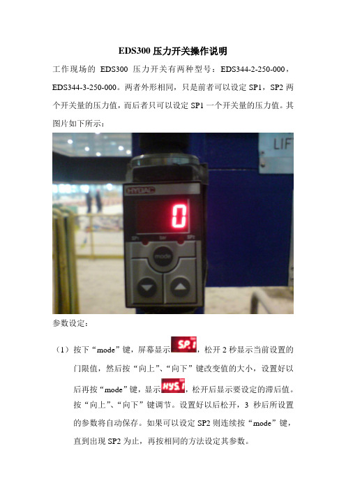
工作现场的EDS300压力开关有两种型号:EDS344-2-250-000,EDS344-3-250-000。
两者外形相同,只是前者可以设定SP1,SP2两个开关量的压力值,而后者只可以设定SP1一个开关量的压力值。
其图片如下所示:
参数设定:
(1)按下“mode”键,屏幕显示,松开2秒显示当前设置的门限值,然后按“向上”、“向下”键改变值的大小,设置好以
后再按“mode”键,显示,松开后显示要设定的滞后值。
按“向上”、“向下”键调节。
设置好以后松开,3秒后所设置
的参数将自动保存。
如果可以设定SP2则连续按“mode”键,直到出现SP2为止,再按相同的方法设定其参数。
(2)当参数设定完之后将“向上”、“向下”键同时按下5秒之后将显示,将对刚才所设定的参数进行保存,松开之后将
显示或,通过“向上”、“向下”键来选择,当显示为时按下“mode”键为解锁状态,即SP1
(SP2)的参数可以修改;当显示为时按下“mode”
键为锁定状态,即SP1(SP2)的参数不可以修改。
EDS300压力开关说明书
4 pole plug, M12x1
ON
OFF
SP = switching point HY = switch-back hysteresis RSP = switch-back point (switching point minus switch-back hysteresis)
2
Electrical accessories:
ZBE 01 Right-angled plug (3 pole + earth) to DIN 43650/ISO 4400 (supplied with the EDS 345 as standard)
34.20
MechaBE 06-02 (for EDS 346) Right-angled plug (4 pole, M12x1) with 2 m lead ZBE 06-05 (for EDS 346) Right-angled plug (4 pole, M12x1) with 5 m lead ZBM 14 connection adaptor G¼ female thread - G¼ male thread for optimum alignment of the pressure switch
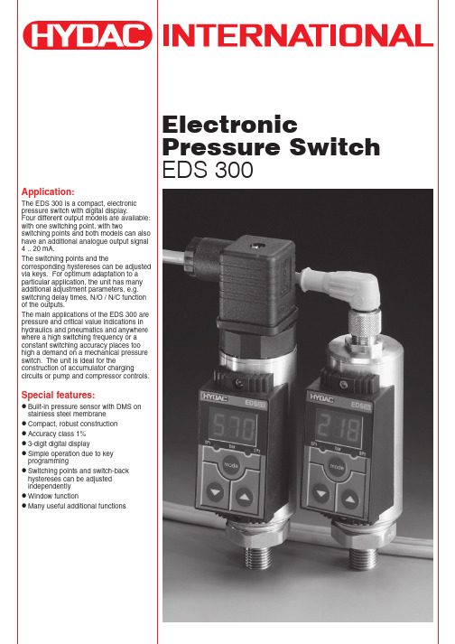
Special features:
Built-in pressure sensor with DMS on stainless steel membrane Compact, robust construction Accuracy class 1% 3-digit digital display Simple operation due to key programming Switching points and switch-back hystereses can be adjusted independently Window function Many useful additional functions
ES300使用说明书

ES300能源计量控制器产品说明书北京华控自动化系统有限责任公司ES300简介ES300 能源计量控制器采用 16 位高精度 A/D转换器,先进的微处理器及浮点数运算方式,有效的保证了整机的信号测量精度和流量计量精度。
产品为 128×64 图形点阵液晶显示器,通过简单的设置可以实现对饱和蒸汽、过热蒸汽、液体和混合气体流量等参量的计量,并可以实现压力补偿密度,温度补偿密度,温度、压力补偿密度等。
ES300 能源计量控制器具有多种网络通信方式,仪表地址及通信波特率可通过窗口参数调整。
同一条总线上可挂接多个仪表。
ES300 能源计量控制器可直接与多种流量计配套,操作简易,功能齐全,可靠性高。
ES300 主要性能指标1、流量输入信号:传感器:差压、涡街、电磁、涡轮信号类型:0~10mA、4~20mA、脉冲(1~5,000Hz)2、压力输入信号(补偿信号):传感器:压力变送器信号类型:0~10mA、4~20mA3、温度输入信号(补偿信号):传感器:温度变送器、铂电阻(三线制)信号类型:0~10mA、4~20mA、Pt100等数据更新周期:≤0.5s4、基本误差:频率信号输入:读数的 0.1%温度信号输入:±0.5℃(-200~560℃)电压电流输入:满量程的±0.1%补偿后流量显示:满量程的±0.2%5、通信功能:具有RS485、以太网通信接口。
6、具有多种流量运算模式,可程序设定组合。
7、具有密度自动补偿功能,可程序设定组合。
8、显示功能:可显示累积流量、瞬时流量、密度、压力、温度、电流、频率、当前时间、系统信息及停电记录。
9、断电保护功能:机内的运算结果和用户设定的数据在断电时不会丢失,保存时间在十年以上。
11、供电电压:24VDC±10%12、功耗:<5W13、工作温度:-20℃~+70℃14、储藏温度:-30℃~+80℃15、相对湿度:≤90%16、外观尺寸:145mm×90mm×57mm17、重量:0.35kg工作原理安装方式本仪表采用标准 DIN35导轨,只需安装好导轨,将仪表固定在导轨上即可。
贺德克压力开关EDS3000操作手册

操作手册EDS3000目 录1. 功能2. 安装3. 操作键4. 数显5. 输出功能5.1. 开关量输出5.1.1. 开关点设置5.1.2. 视窗功能设置5.2. 模拟量输出5.3. 开关点和延滞的设置, 视窗功能的开关值设置5.4. 开关量输出的设置范围6. 基本设置6.1. 基本设置的变更6.2. 基本设置的概要7. 编程锁定7.1. 更改工作状态下的编程锁定7.2. 更改总编程锁定8. 故障信息9. 线路图10. 技术参数10.1. EDS3000(陶瓷芯片); 绝对和相对压力≤16 BAR10.2. EDS3000(薄膜DMS芯片); 相对压力≥40 BAR11. 订货代号11.1. EDS3000(陶瓷芯片); 绝对和相对压力≤16 BAR 11.2. EDS3000(陶瓷芯片); 绝对和相对压力≤16 BAR符合DESINA®标准11.3.EDS3000(薄膜DMS芯片); 相对压力≥40 BAR11.4.EDS3000(薄膜DMS芯片); 相对压力≥40 BAR符合DESINA®标准12. 附件12.1. 用于电气连接12.2. 用于机械连接13. 安装尺寸通电后,该装置先短时显示“示。
通过按键显示最大值,并持续5. 输出功能5.1 开关量输出EDS 3000有1路或2路开关量输出。
在基本设置下,可对如下开关量进行设置:5.1.1 开关点设置(SP)每路开关量输出可设定一个开关点和一个延滞。
相应的输出会在达到预设开关点时切换并在压力下降到回复点以下时切换回复。
预设延滞决定开关回复点。
(开关回复点=开关点-延滞)缩记: “S.P.1”, “S.P.2” = 开关点1或2“H.Y.1”, “H.Y.2”= 延滞1或25.1.2 视窗功能设置(WIN)视窗功能可监测一定范围内的情况。
对于每路开关量输出而言,设置一个高位开关值和一个低位开关值,由该两个值确定监测范围。
当压力上升进入到低位开关值,则相应输出发生切换。
压力变送器详细操作指南
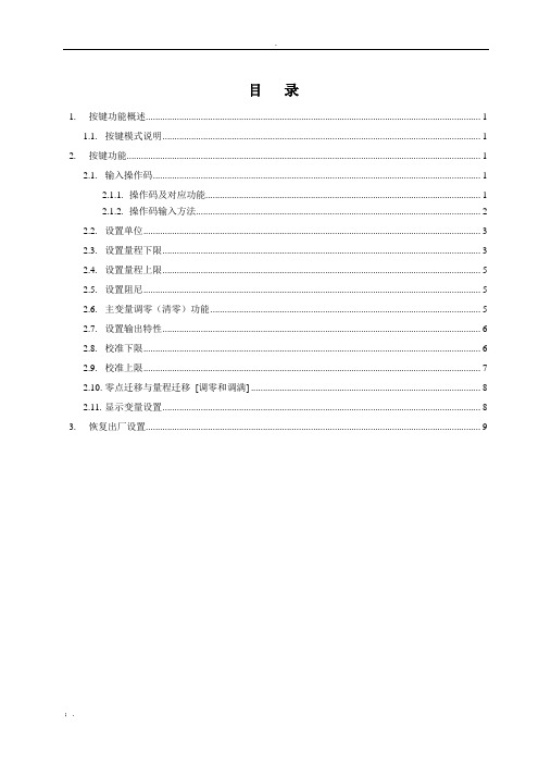
目录1. 按键功能概述 (1)1.1. 按键模式说明 (1)2. 按键功能 (1)2.1. 输入操作码 (1)2.1.1. 操作码及对应功能 (1)2.1.2. 操作码输入方法 (2)2.2. 设置单位 (3)2.3. 设置量程下限 (3)2.4. 设置量程上限 (5)2.5. 设置阻尼 (5)2.6. 主变量调零(清零)功能 (5)2.7. 设置输出特性 (6)2.8. 校准下限 (6)2.9. 校准上限 (7)2.10. 零点迁移与量程迁移[调零和调满] (8)2.11. 显示变量设置 (8)3. 恢复出厂设置 (9)按键详细操作指南1.按键功能概述1.1. 按键模式说明标准的H3051S和H3051T表头上都有三个按键,分别为“M”、“S”、“Z”。
也支持外部扩展干簧管接口,实现不开盖调整。
此时支持两个按键,分别为“S”、“Z”。
针对这两种应用,本产品支持“双按键”和“三按键”两种操作模式。
“三按键”操作模式:操作更快捷,适用于LCD上具备3个按键的产品。
➢Z键用于进入提示数据设置界面和移位;➢S键用于进入数据设置界面、增加数字和数据保存;➢M键用于数据保存。
注:在三按键模式下,任何时候都可以按下“M“键,保存当前的设置数据。
“双按键”操作模式:这种操作模式通常用于外部只有2个非接触按键的情况。
➢Z键用于进入提示数据设置界面和移位;➢S键用于进入数据设置界面、增加数字和数据保存。
注:在双按键模式下,输入数据时,必须等左下角的下箭头闪烁时,才能通过按下“Z”键保存设置数据。
2.按键功能2.1. 输入操作码2.1.1.操作码及对应功能现场使用按键组态时,LCD左下角“88”字符用于表示当前设置变量类型,也就是当前按键所执➢例如输入“5”,直接进入设置阻尼功能。
➢例如输入“8”,直接进入设置输出特性。
➢例如输入“9”,直接进入校准下限。
2.1.2.操作码输入方法图例说明:1.均以当前采集值1 kPa,量程为0~100kPa为例2.2. 设置单位2.3. 设置量程下限2.4. 设置量程上限2.5. 设置阻尼2.6. 主变量调零(清零)功能2.7.设置输出特性2.8.校准下限2.9.校准上限2.10.零点迁移与量程迁移[调零和调满]2.11.显示变量设置液晶显示屏能显示“电流”、“百分比”、“主变量”三种变量的一种或交替显示其中的两种(间隔时间4秒)。
- 1、下载文档前请自行甄别文档内容的完整性,平台不提供额外的编辑、内容补充、找答案等附加服务。
- 2、"仅部分预览"的文档,不可在线预览部分如存在完整性等问题,可反馈申请退款(可完整预览的文档不适用该条件!)。
- 3、如文档侵犯您的权益,请联系客服反馈,我们会尽快为您处理(人工客服工作时间:9:00-18:30)。
EDS300压力开关操作说明
工作现场的EDS300压力开关有两种型号:EDS344-2-250-000,EDS344-3-250-000。
两者外形相同,只是前者可以设定SP1,SP2两个开关量的压力值,而后者只可以设定SP1一个开关量的压力值。
其图片如下所示:
参数设定:
(1)按下“mode”键,屏幕显示,松开2秒显示当前设置的门限值,然后按“向上”、“向下”键改变值的大小,设置好以
后再按“mode”键,显示,松开后显示要设定的滞后值。
按“向上”、“向下”键调节。
设置好以后松开,3秒后所设置
的参数将自动保存。
如果可以设定SP2则连续按“mode”键,直到出现SP2为止,再按相同的方法设定其参数。