风速传感器说明书
Met One 010C 风速传感器用户手册说明书

MODEL010CWIND SPEED SENSOROPERATION MANUALMet One Instruments, IncCorporate Sales & Service: 1600 NW Washington Blvd. Grants Pass, OR 97526 Tel (541) 471-7111 Fax (541) 471-7116******************1.0 GENERAL INFORMATION1.1 The 010C Wind Speed Sensor uses a durable, three-cup anemometer assembly andsolid-optical link with a 40-slot chopper disk to produce a pulsed output whosefrequency is proportional to wind speed. An internal heater reduces moisture forextended bearing life. This sensor is usually used in conjunction with the 191 Cross arm Assembly. The sensor may be used with a translator module, or used directlywith a variety of data loggers.1.2 The Sensor Cable has a quick-connect connector with vinyl jacketed, shielded cable.Cable length is given in -XX feet on each cable part number. A 1953-XX cable isused with translators having terminal strip connections.Table 1-1Model 010C Wind Speed Sensor SpecificationsPerformance CharacteristicsMaximum Operating Range 0-60 meters/sec or 0-125 mphStarting Speed 0.27 meters/sec or 0.6 mphCalibrated Range 0-50 meters/sec or 0-100 mphAccuracy ±1% or 0.15 mphTemperature Range -50︒C to +85︒CResponse Distance constant less than 5 ft of flow**The distance traveled by the air after a sharp-edged gust has occurred for theanemometer rate to reach 63% of the new speed. Distant constant less than 15ft of flow with optional 010C-1 aluminum cupset.Electrical CharacteristicsPower Requirements 12 VDC at 10 mAOutput Signal 11-volt pulseOutput Impedance 100 ohms maximumHeater Power Requirement 12 VDC at 350 mAStandard Cable Length 300’ maximum (consult factory if longercable is to be used for special requirements) Physical CharacteristicsWeight 1.1 poundsFinish Anodized aluminumMounting Use with 191 CrossarmCabling 1953-XX Cable (XX is cable length in feet)Optional AccessoriesA. External heater and power supply for extreme low temperature operation.B. Ice Skirt for extreme icing environments.C. Aluminum cup assembly.2.0 INSTALLATION2.1 The 010C Wind Speed InstallationA. Mount the cup assembly and secure with the Allen head set screw, check to seethat the cup assembly rotates freely.B. Install the sensor in the end of the Model 191 Crossarm Assembly (the endwithout the bushing).C. Tighten the locking set screw. Do not over-tighten. Apply a small amount ofsilicone grease to set screws to prevent freezing in adverse environments.D. Connect the cable assembly to the keyed sensor receptacle and tape it to themounting arm.2.2 WiringA. The cable assembly contains five wires. Typical wiring hookup is shown inFigure 2-1.No Connection White/Brown ShieldElectrical ConnectorView looking at connector pins. (Pins are also identified on connector).2.3 Lightning ProtectionA. Weather sensors are sensitive to direct or nearby lightning strikes. A well-grounded metal rod or frame should be placed above the sensor installation. Inaddition, the shield on the signal cable leading to the translator must beconnected to a good earth ground at the translator end and the cable routeshould not be vulnerable to lightning.3.0 OPERATIONAL CHECK-OUT AND CALIBRATION3.1 010C Wind Speed Sensor Check-OutA. Spinning the anemometer cup assembly will produce a series of pulses (40pulses per revolution). To verify sensor output, monitor this signal with either thetranslator module, data logger, or an oscilloscope. (Refer to Frequency vs. WindSpeed Table 3-1). Spinning the hub of the wind speed transmitter without thecup assembly mounted and allowing it to coast to a stop will give a goodindication of threshold performance; a jerky or sudden stop indicates damage tobearings, bent drive shaft, or obstruction in the light chopper.B. Inspect the cup assembly for loose cup arms or other damage. The cupassembly cannot change calibration unless a mechanical part has come loose orhas been broken. If a cup arm is loose or broken the calibration of the sensormay be affected.C. If the sensor heater is used, check internal heater operation by sliding sensorcover down and touching the housing behind the printed circuit board. Thehousing should feel warmer than the adjoining metal parts. The sensor has abuilt-in heater that is designed to provide a raise in the internal temperature,providing a small amount of positive pressure. This heater requires as external12 V (@500ma) power supply.FREQUENCY vs WIND SPEED FOR 010 SENSORTABLE 3-1Transfer FunctionsMiles per hour: Meters per second:rpm = 16.767 * (V mph - 0.6) rpm = 37.522 * (V m/s - 0.27) V mph = (rpm / 16.767) + 0.6 V m/s = (rpm / 37.522) + 0.27 f Hz = (V mph - 0.6) / .08946 f Hz = (V m/s - 0.27) / 0.039976 V mph = V m/s * 0.44704 V m/s = V mph / 0.447044.0 MAINTENANCE AND TROUBLESHOOTING4.1 General Maintenance Schedule*6 – 12 Month Intervals:A. Inspect sensor for proper operation per Section 4.2.B. Replace wind speed sensor bearings in extremely adverse environments perSection 4.5.12 – 24 Month Intervals:A. Recommended complete factory overhaul of sensor.*Schedule is based on average to adverse environments.Table 4-1010C Wind Speed Sensor TroubleshootingSymptom Probable Cause Solution Refer toNo wind speed output Loss of supplyvoltage Check translator +12supply & connectingcablesFigure 2-1Faulty integratedamplifierReplace circuit board Section 4.5Faulty diodes,D1, D2Replace circuit board Section 4.5Faulty detector Replace detector Section 4.6No wind speed outputbelow 2-5 mphBad bearing(s) Replace bearing(s) Section 4.4Faulty detector Replace detector Section 4.6Wind speed signal drops ouas speed increasesFaulty detector Replace detector Section 4.64.2 010C Wind Speed Sensor: 6 – 12 Month Periodic ServiceA. At the crossarm assembly, disconnect the quick disconnect plug from the sensor(leave the cable secured to the crossarm) and remove the sensor from thecrossarm assembly.B. Loosen the set screw holding the cup assembly. Support the rotating hub of thesensor with one hand and pull the anemometer cup assembly free.C. Visually inspect the anemometer cups for cracks and breaks. Also, make surethat each arm is securely attached to the cup assembly hub.D. Slide the sensor cover down to expose the light-chopper disc assembly, lightsource, detector, and circuit board.E. Inspect the interior of the sensor for any signs of corrosion and/or dust buildup.F. Inspect the light-chopper for cracks, and make sure that all slots are free ofcorrosion.G. Inspect the signal-conditioning module for cracks and corrosion around solderedconnections.H. Rotate the sensor hub assembly to ensure that it turns freely and that the sensorbearings are not damaged. Make sure the light-chopper assembly is notcontacting the light source and detector.I. Apply a small amount of silicone lubricant. (Dow-Corning DC-33 or equivalent) tothe sensor O-ring seals; slide the cover up over the sensor and wipe off anyexcess lubricant.J. A moisture vent is located on the base of the sensor; make sure that this vent is clear.K. Re-install sensor according to installation procedure (Section 2.0); verify proper operation using procedures in Section 3.0.4.3 010C Wind Speed Sensor Maintenance (Refer to 010C Sensor Assembly Drawing)The following procedures require a relatively clean, dry work area, a source of 12VDC power at approximately 20 mA, and an oscilloscope (DC to 10 KHz minimumrange required.4.4 Sensor Bearing Replacement. (Refer to 010C Sensor Assembly Drawing)A. Remove sensor from tower and remove cup assembly (1). Refer to Section 4.2.B. Disassemble sensor and remove old bearings (6).1. Slide the sensor cover (16) down to expose the light-chopper discassembly (10), detector assembly (12) and circuit board (18).2. Loosen both special set screws on the shaft of the light chopper assembly(11).3. Support the light-chopper assembly (10) with one hand and slowly pullthe rotating hub/shaft assembly (2) out of the column (8).4. Remove the shield (4) and slinger (5) from the column (8).5. Remove the light-chopper assembly (10) from the sensor housing, beingcareful not to damage the slots located between the light-chopper holderand the lower bearing.6. Insert the lower end of the rotating hub/shaft assembly into the upperbearing, cock it slightly to one side and push out the lower bearing.7. Insert a right-angle type of tool, such as an Allen wrench, into the upperbearing; cock it slightly to one side and remove the bearing.8. Clean dirt from bearing bores, using a cotton swab and alcohol.C. Install the new bearings and assemble the sensor.1. Install new upper and lower bearings in the column (8). Bearings shouldslide easily into bearing bores.2. Install a slinger and shield (4, 5) on the column assembly. Use new partsif old ones are damaged or corroded.3. Insert the rotating hub shaft (2) into the column assembly (8), through theshield (4), slinger, and upper bearing, until it starts to protrude through thelower bearing.4. Support the light-chopper assembly (10) with one hand and slowly pushthe rotating hub shaft into it until the shaft almost touches the bottom.5. Tighten both special set screws on the light-chopper assembly; do notover tighten as the set screw tips will damage the shaft.6. Rotate the sensor hub assembly (2) to ensure that it turns freely and thatan endplay of about .005” exis ts.7. Hold sensor vertically and make sure that the light-chopper assembly (10)is not contacting the detector assembly (12).8. Apply small amount of silicone lubricant (Dow-Corning DC-33 orequivalent) to the sensor O-rings (9); slide the cover (16) up over thesensor and wipe off any excess lubricant.D. Replace cup assembly and re-install (refer to Section 2.0)4.5 1200-1 Circuit Board Assembly Replacement (Refer to 010C Assembly Schematic)A. Remove sensor from tower and remove cup assembly (refer to Section 4.2).B. Slide the sensor cover (16) down to expose the light-chopper disc assembly (10),detector assembly (12), and circuit board (18).C. Remove two screws (17) holding circuit board assembly (18) and lift circuit boardaway from sensor housing.D. Note color of wires and then unsolder wires to detector assembly from circuitboard and three wires from connector (19).E. Install new circuit board assembly by reversing above procedure.4.6 Detector Assembly Replacement Refer to 010C Assembly Schematic)NOTE: 010C sensors SN M10560 and later use 520253 photodetector. Oldersensors use 1074 photodetector assemblies.A. Remove sensor from tower and remove cup assembly. Refer to Section 4.2.B. Slide the sensor cover (16) down to expose the light-chopper disc assembly (10),detector assembly (12) and circuit board (18).C. Remove two screws (17) holding circuit board assembly (18) and lift circuit boardaway from sensor housing.D. Note color of wires and then unsolder wires to detector assembly from circuitboard (18).E. Remove two screws (20) holding detector assembly (12) and remove assembly.F. Install new detector assembly by reversing above procedures.4.7 010C Wind Speed Sensor Repair and Recalibration ServiceThe factory provides fast, economical service for the user. This repair andcalibration service includes disassembly and detailed inspection of all movingmechanical parts and electronic components.Service includes replacement of bearings, regardless of apparent condition, andfunctional test of sensor. Replacement of the following items is also included: O-rings, shield and slinger, shaft, set screws. Other components will be replaced as required. Only charges for additional materials will be added to the basic service charge.Table 4-2Replacement 010C Parts ListRef No.U Description Part No.1 Cup Assembly Lexan - 2672Aluminum – 2672-1 2 Hub/Shaft Assy. 26584 Shield 10095 Slinger 10106 Bearing 10559 O-ring 72012010 Chopper Wheel Assembly 220211 Set Screw 60125012 Photo Detector 520253*13 Heater Clamp 48010014 Heater 80508016 Sensor Cover 267517 PCBA Mounting Screws 60124018 PCBA 1200-120 Detector Assembly Mounting Screws 60127022 Standoff 86005023 Integrated Amplifier 62030024 Nut, Hex, Kep 4-40 60040025 Screw FH 82︒ 4-40 x 3/8 60133026 Screw FH 82︒ 4-40 x ¼ 601240NOTE: 010C sensors SN M10560 and later use the black 520253 photodetector. Earlier sensors use the white 1074 photodetector assemblies.。
风速仪使用说明书
风速仪使用说明书一、产品介绍风速仪是一种用于测量风速的仪器。
它采用先进的传感技术和精密的测量算法,可以准确地测量当前的风速,并提供相关的数据显示和功能操作。
二、产品特点1. 准确性:风速仪采用高精度传感器,能够提供可靠准确的风速测量结果。
2. 多功能:风速仪除了测量风速外,还具备其他功能,如温度测量、湿度测量等。
3. 操作简便:风速仪的界面设计简单直观,用户只需按照指示进行操作即可。
4. 轻便易携:风速仪体积小巧轻便,方便携带使用。
三、使用步骤1. 打开风速仪电源:按下电源按钮,风速仪将启动并显示相关信息。
2. 选择测量模式:风速仪支持多种测量模式,如即时测量模式、平均测量模式等。
根据实际需求,选择相应的测量模式。
3. 进行风速测量:将风速仪朝向所需测量的风口或空气流动方向,将风速仪保持稳定,并等待一段时间,待测量结果稳定后,记录当前的风速数值。
4. 其他功能操作:如果需要进行温度测量、湿度测量等功能操作,可按照相应功能按钮进行操作。
四、注意事项1. 防止碰撞:使用过程中避免将风速仪与其他硬物碰撞,以免影响仪器的正常工作。
2. 避免湿润环境:尽量避免在潮湿或有水滴的环境中使用风速仪,以免影响仪器的测量准确性。
3. 避免高温环境:风速仪在高温环境下可能会受到损坏,因此请避免将其暴露在过高温度的环境中。
4. 定期校准:为保证测量结果的准确性,建议定期对风速仪进行校准,可参考相关的校准方法和标准。
五、维护与保养1. 充分充电:使用前请确保风速仪已充满电,以免因电量不足影响仪器的正常使用。
2. 清洁保养:使用后请用清洁软布擦拭风速仪表面,避免灰尘和污渍影响仪器的使用效果。
3. 安全存放:在长时间不使用时,请将风速仪存放在干燥、通风的环境中,避免受潮或受损。
六、故障排除1. 无法正常启动:检查电池电量是否充足,如电池电量不足,请及时充电。
2. 测量结果异常:检查是否操作错误或环境异常导致,如确认操作正确且环境正常,可尝试重新测量或进行校准。
风力发电机的风速传感器说明书

风力发电机的风速传感器说明书感谢您购买我们的风力发电机风速传感器。
此说明书将为您提供有关传感器原理、安装及使用的详细信息。
在使用前,请仔细阅读本说明书。
若有任何疑问,请随时联系我们的技术支持部门。
一、传感器原理本传感器采用了先进的超声波技术来测量风速。
传感器内部的超声波发射器将信号发送到空气中。
超声波信号会撞击空气中的颗粒,并被反射回传感器内部的接收器。
通过测量超声波信号发送和接收之间的时间差,我们可以计算出空气中的风速。
二、安装为了确保传感器的测量结果准确,我们需要在安装传感器时注意以下事项:1.传感器应该安装在风力发电机的传动轴上方,并且距离传动轴至少50公分的位置。
这样可以避免传感器被风力发电机直接影响,从而影响测量结果。
2.传感器应该安装在离地面50公分的高度处,这样可以避免地面风向等因素对传感器的影响。
3.在安装传感器之前,请确保传感器配件齐备。
如有任何配件缺失或者损坏,请联系我们的客服部门。
三、使用本传感器具有自动校准功能,不需要手动校准。
在每次使用之前,请先进行一次预热。
预热时间约为30秒钟。
在使用时,请注意以下事项:1.传感器应该朝向风向。
如果传感器朝向错误,测量结果将会产生误差。
2.请勿将传感器安装在垂直风速较大的区域。
在一些气象条件下,会有上下行程的风,导致该区域的风速波动较大,从而影响测量结果。
3.传感器不能直接暴露在太阳下,必须加装遮阳罩,以确保测量结果的准确性。
四、维护本传感器无需特别维护。
如出现故障,请联系我们的客服部门进行维修。
五、注意事项1.请勿将传感器强行拆卸或修理。
如需进行维修,请联系我们的技术支持部门。
2.如使用过程中出现异常,请停止使用传感器并联系我们的客服部门。
3.请勿将传感器暴露在极端条件下。
如极端温度或湿度环境下使用传感器,可能会导致传感器出现故障。
希望本说明书可以为您的使用提供帮助。
如果您需要更多的技术支持或者有其他疑问,请联系我们的客服部门。
再次感谢您对我们的产品的信任和支持。
GFY15双向风速传感器说明书

(5) 复电点: 按遥控器面板上的“功能+”或“功能-”,使数码管显示“5 XXX”(出厂时设为 1.2),用户需要调整时,按“参数+”或“参数-”使数码管显示为用户要求值。
(7) 测试点: 测试功能主要是通过此功能检测其声光报警及输出是否正常。按遥控器面板上的 “功能+”或“功能-”使数码管显示“7 XXX”(0-15.0 可任意设置),用户需要调整时,按“参数+” 或“参数-”,使数码管显示为用户要求值。
注意:每次参数调整完毕后必须按“退出”键,以保证参数被有效的保存,如果没有按“退出” 键或其它键,30 秒后参数不保存自动退出到测量状态。 5 使用注意事项
上下左右晃动,距传感器 20m 范围内不能有遮挡物体存在,以免挡住风流,影响传感器的正常测量。
4.2 传感器接线
本传感器的外部接线采用航空插座方式,外配一个带航空插头的 1.5 米电缆线(型号 MHYVR-1×5× 7/0.3,外径约 8mm)。航空插头各引脚的定义及电缆芯线的对应关系如下:
1 号脚 -- 电缆红芯 --- 电源 + 2 号脚 -- 电缆白芯 --- 电源 3 号脚 -- 电缆蓝芯 --- 信号 + 4 号脚 -- 电缆绿芯 --- 信号 – 5 号脚 -- 电缆黄芯 --- NC(空) 4.3 传感器的使用
(4)传感器所接电缆要求:采用分布参数为(R≤12.8Ω/km、C≤0.06μF/km、L≤0.8mH/km)
的传输电缆时,传输距离不小于 2km。
11 附件及资料
风速传感器说明书

风向变送器STEWD-YM039说明书测量参数量 程:0~360°或16风向,“北”由传感器上箭头标志指定测量精度: ±5°或1个风向启动风速:0.2~0.5 m/S换算公式:电压型0-15=电压V*7.5(±40mV 误差区间)电流型0-15=(电流-4mA)/1.06666(±0.4mA 误差区间)使用环境:-30℃~70℃/0-100%RH(可轻度沙尘/凝露,结冰情况下不适用)电路参数 电压型 电流型 数字型 注意事项 附:十六风向表 工作电压12V(7-24V) 12/24V 12V(7-24V) 纹波<200mV 北、东北偏北、东北、东北偏东、东、东南偏东、东南、东南偏南、南、西南偏南、西南、西南偏西、西、西北偏西、西北、西北偏北 静态功耗8-15mA 15-30mA 8-15mA 浪涌防护不可替代引雷器或防雷器 输出方式0-2V/0-5V 4-20mA RS485(ModBus-04) 雷击浪涌 600W@1000uS 600W@1000uS 600W@1000uS 功能特点采用铝合金及不锈钢结构,铝阳极氧化表面处理与静电喷涂处理,精巧坚固,法兰式安装,使用方便 具备较为全面的防护措施及抗干扰能力,可在多种气候条件下使用数字型采用标准ModBus 协议,04号读寄存器指令,CRC16校验方式(指令格式请自行参阅有关资料) 引线定义红线 黄线 绿线 黑线 注意事项 电压/电流型电源正 信号正 信号负/地 电源负/地 信号负与电源负可并联合并 数字型 电源正 485-/A 485+/B 电源负/地 请勿对485信号线施加电压 注意事项(电流输出型默认输出匹配100欧下拉电阻,250欧请事先说明,仅限24V 供电!)如无特殊要求,信号输出将不具备反向保护及过压、过流保护功能,请勿将信号线接错,以防损毁! 传感器线缆屏蔽层一般情况下已与电源地线短路,接线时请妥善处理屏蔽线,防止电源短路或故障! 适用范围采用高性能磁敏元件,并运用独特的处理算法,可实现对环境风向角度的测量,并输出标准的信号。
风速传感器使用说明书

最高位,检查最低位;
4、如果最低位为 0:重复第 3 步(再次移位) 如 果 最 低 位 为 1 : CRC 寄 存 器 与 多 项 式 A001(1010 0000 0000 0001)进行异或;
5、重复步骤 3 和 4,直到右移 8 次,这样整个 8 位数据全部进行了处理;
L:风速测量范围(m/s))
电压型(0-2.5V):
W =V/2.5×L
(W:风速示值(m/s);V:电压信号(0-2.5V);
L:风速测量范围(m/s))
接线方法
传感器底部有一个 5 芯航空插头,其针脚对应 的管脚定义如图所示。
(1)若配备本公司生产的气象站,直接使用传感 器线将传感器与气象站上的相应接口相连即 可。
大树枝可折断。
树木可被吹倒,一般建筑物遭 10 狂风
破坏
大树可被吹倒,一般建筑物遭 11 暴风
严重破坏
13.9~17.l 17.2~20.7 20.8~24.4 24.5~28.4 28.5~32.6
12 飓风 陆上绝少,其催毁力极大
>32.6
4
5.5~7.9
清劲 有叶的小树摇摆,内陆的水面 5
风 有小波,高的草波浪起伏明显
8.0~10.7
大树枝摇动,电线呼呼有声,
6 强风
10.8~13.8
撑伞困难,高的草不时倾伏于地
全树摇动,大树枝弯下来,迎 7 疾风
风步行感觉不便
可折毁小树枝,人迎风前行感
8 大风
觉阻力很大
草房遭受破坏,屋瓦被掀起, 9 烈风
2
49 m m
风速传感器 V1.0 TR-FS02
风速传感器 说明书
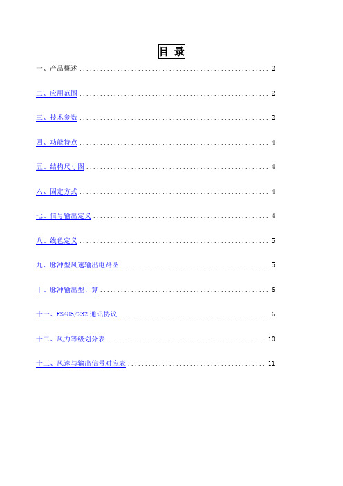
一、产品概述 (2)二、应用范围 (2)三、技术参数 (2)四、功能特点 (4)五、结构尺寸图 (4)六、固定方式 (4)七、信号输出定义 (4)八、线色定义 (5)九、脉冲型风速输出电路图 (5)十、脉冲输出型计算 (6)十一、RS485/232通讯协议 (6)十二、风力等级划分表 (10)十三、风速与输出信号对应表 (11)一、产品概述该三杯式风速传感器是我公司自主研发、生产的一款风速测量仪器,本品由壳体、风杯和电路模块组成,内部集成光电转换机构、工业微电脑处理器、标准电流发生器、电流驱动器等。
传感器壳体和风杯采用铝合金材料,使用特种模具精密压铸工艺,尺寸公差甚小表面精度甚高,内部电路均经过防护处理,整个传感器具有很高的强度、耐候性、防腐蚀和防水性。
电缆接插件为军工插头,具有良好的防腐、防侵蚀性能,能够保证仪器长期使用,同时配合使用风速传感器内部进口轴承系统说明书,确保了风速采集的精确性。
电路PCB采用军工级A级材料,确保了参数的稳定和电气性能的品质;电子元件均采用进口工业级芯片,使得整体具有极可靠的抗电磁干扰能力,能保证主机在-20℃~+50℃,湿度35%~85%(不结露)范围内均能正常工作。
二、应用范围本产品可广泛运用于工程机械(起重机、履带吊、门吊、塔吊等)领域,铁路、港口、码头、电厂、气象、索道、环境、温室、养殖、空气调节、节能监控、农业、医疗、洁净空间等领域风速的测量,并输出相应的信号。
三、技术参数□脉冲输出型:□ NPN输出□ PNP输出□ NPN输出带内部上拉(4.7KΩ)□RS485通讯型□电压输出型:□ 0-2VDC □ 0-5VDC □ 0-10VDC □电流输出型: 4-20mA电源:根据输出类型不同所需的电压源范围不同电流输出型: 12~24V电压输出型:输出0-2VDC:6~24V输出0-5VDC:6~24V输出0-10VDC:12~24V脉冲输出型:5~24V量程:□0-30m/s □0-60m/s负载能力: □其他□<500Ω□>2kΩ最大功耗(DC24V): 脉冲型MAX≤200mW;电压型MAX≤300mW;电流型MAX≤700mW;启动风力:0.4~0.8m/s 重量:≤0.5Kg四、功能特点该产品自投入市场以来,以其优异的质量,卓越的性能赢得广大用户的好评,具备以下特点:◆外观结构设计合理、美观大方,体积小,便于携带,安装简便。
30.5 风速传感器操作手册说明书

MODEL 30.5WIND SENSOROPERATION MANUALDocument No. 30.5-9800 Rev. AMet One Instruments, IncCorporate Sales & Service: 1600 NW Washington Blvd. Grants Pass, OR 97526 Tel (541) 471-7111 Fax (541) 471-7116 - ******************Copyright Notice30.5 Wind Sensor Manual© Copyright 2021 Met One Instruments, Inc. All Rights Reserved Worldwide. No part of this publication may be reproduced, transmitted, transcribed, stored in a retrieval system, or translated into any other language in any form by any means without the express written permission of Met One Instruments, Inc.Technical SupportThis manual is structured by customer feedback to provide the required information for setup, operation, testing, maintaining, and troubleshooting the 30.5 Weather Sensor. If additional support is required after consulting the printed documentation, please contact an expert Technical Service representative during normal business hours of 7:00 a.m. to 4:00 p.m. Pacific Time, Monday through Friday. In addition, technical information and service bulletins are often posted on . Please contact Met One Instruments and obtain a Return Authorization (RA) number before sending any equipment back to the factory. This allows for better tracking and scheduling of service work to expedite customer service. Please have the instrument’s serial number available when contacting the manufacturer.Voice: (541) 471-7111Fax: (541) 471-7116E-Mail: ******************Mail: Technical Services DepartmentMet One Instruments, Inc.1600 NW Washington BlvdGrants Pass, OR 97526Safety NoticeThe contents of this manual have been checked against the hardware and software described herein. Since deviations cannot be prevented entirely, full agreement cannot be guaranteed. However, the information in this manual is reviewed regularly and any necessary corrections are included in subsequent editions. Faultless and safe operation of the product presupposes proper transportation, storage, and installation as well as careful operation and maintenance. The seller of this equipment cannot foresee all possible modes of operation in which the user may attempt to utilize this instrumentation. The user assumes all liability associated with the use of this instrumentation. The seller further disclaims any responsibility for consequential damages.Electrical & Safety ConformityThe manufacturer certifies that this product operates in compliance with the following standards and regulations:FDA/CDRH This product is tested and complies with 21 CFR, Subchapter J, of the Health and Safety Act of 1968 US 21 CFR 1040.10Table of Contents1.Introduction & Overview – 30.5 Wind Sensor (6)1.1.Overview (6)2.Specifications (7)3.Unpacking & Installation (8)3.1.Unpacking (8)3.2.Deployment (9)Tripod / Pipe top Installation: (9)3.3.Input / Output Connections (10)3.4.Operational Checkout (11)3.5.Maintenance (11)3.6.Setting Magnetic Declination (11)er Selectable Options (12)er Interface (13)6.Standard Configuration (14)7.Appendix A (15)7.1.Terminal Mode Commands (15)7.1.1.H,h,? – Display Help Menu (15)7.1.2.AT – Ambient Temperature Printout Toggle On/Off (15)7.1.3.BV – Battery Voltage Printout Toggle On/Off (16)7.1.4.CV – Compass Measurement Printout Toggle On/Off (16)7.1.5.ID – View / Set Instrument ID (16)7.1.6.MA – View / Set Modbus Address (16)7.1.7.ME – Metric or English Units (17)7.1.8.SU –Wind Speed Units (17)7.1.9.TU –Temperature Units (17)7.1.10.MD –Magnetic Declination (18)7.1.11.OI –Output Interval (18)7.1.12.ST – Serial Trigger (19)7.1.13.RT – Output Record Type (19)7.1.14.RV – Software Version Number (19)8.Modbus (20)8.1.Modbus operation: (20)3X Registers (20)4X Registers (20)9.Appendix B (21)9.1.Theory of Operation (21)1. Introduction & Overview – 30.5 Wind Sensor1.1. OverviewThe 30.5 Wind Sensor provides measurements of wind speed and wind direction in a single, compact, rugged unit. It integrates a folded-path, low-power sonic anemometer. It also includes an internal compass that allows for automatic alignment of wind direction to magnetic north, regardless of the sensor’s orientation.The small footprint and power efficiency of the 30.5 make it ideal for remote regions, urban environments, air quality networks, construction/remediation sites, and other network applications. The sensor works well in permanent (cooperative weather networks, schools, public information dissemination) or temporary (emergency response, audit, research program support) installations.Designed for maximum portability and utility, the 30.5 is well suited for rapid deployment and use by one person under all conditions. The unit may be mounted on a tower, tripod, or vehicle mast. Data outputs are a serial, digital message as well as simple analog voltage outputs that can be interfaced to most data logging systems.2. SpecificationsPARAMETER SPECIFICATION Wind Speed Operating Range 0 to 60 m/s (0 to 134 mph)Wind Speed Accuracy Digital outputs:±0.5 m/s (1.1 mph) or 5% of reading, whichever is greater Analog output:Digital accuracy +/-1mVWind Speed Resolution 0.1 m/s (0.1 mph) Wind Speed Starting Threshold 0.1 m/s (0.1 mph) Wind Direction Range 0 to 360 degreesWind Direction Accuracy Digital outputs:±5° (including Compass) Analog output:Digital accuracy +/-1mVWind Direction Resolution 1.0°Alignment Compass Accuracy ±2°Alignment Compass Resolution 1°Measurement Rate Output 1 HzSignal Output Types RS-232, RS-485, and 0-1VDCMax Cable Lengths RS-232: 15M (50FT)RS-485: 1230M (4000FT) Analog: 100M (325FT)Power Supply 9-36 VDC, current draw 40mA @ 12 VDC typical Operating Temperature -40 to +60 °C (-40 to +140 °F)Operating Relative Humidity 0 to 100%Dimensions 6 inches (152 mm) diameter, 11 inches (279 mm) height Shipping Weight 6 pounds (2.72 kg) (including packaging)3. Unpacking & Installation3.1. UnpackingAny damages incurred to the equipment during shipping are the responsibility of the carrier. If any damage to the shipment is noticed before unpacking, a claim must be filed with the commercial carrier immediately. Please follow any special unpacking instructions provided by the carrier as items are carefully removed from the containers and inspected. It is recommended to document and photograph all damaged packages and items before, during, and after unpacking them.Unpack the 30.5 and accessories and make a visual inspection of the contents; contact the supplier if anything is missing. The 30.5 Weather Sensor ships with the following items:∙30.5 Wind Sensor.∙Calibration certificate.∙Operation manual (this document).Optional Accessories that may be purchased include:∙2954 ¾” IPS pipe vertical mounting adaptor∙WeatherView SoftwareThe required 10624 signal cable is sold separately. It is available in 5M, 12M and 25M lengths. Inquire with Met One Sales or Service groups for other length cables.Contact Met One Instruments (see the Technical Support section at the beginning of this manual) to arrange for any replacement items needed.Please keep the carton(s) and associated packing materials for reuse.3.2. DeploymentTripod / Pipe top Installation:The 30.5 can be quickly and easily deployed on top of a Met One 905 tripod or any other vertical ¾” IPS pipe using the optional 2954 vertical mount.3.3. Input / Output Connections10624 Cable Wire Color Designations:RED POWER POSITIVE (9-36VDC, 40mA nominal @ 12VDC)BLK POWER COMMONBLU ANALOG COMMONGRN SIGNAL COMMONWHT RS-232 TXBRN RS-232 RXYLW RS-485+GRY RS-485-ORN WIND SPEED ANALOG OUT 0-1VDCVIO WIND DIRECTION ANALOG OUT 0-1VDCWHT/BRN SHIELD (must be grounded for transient protection to function) Warning: Unused wires should be isolated and tied back. Take care that wires do not touch each other while power is applied or damage to sensor may occur.Maximum Cable Length Considerations:The maximum recommended cable length depends on the communication protocol to be used:RS-232 50FT maximumRS-485 4000FT maximumANALOG 300FT maximum3.4. Operational CheckoutConnect the 30.5 serial or analog signal wires to a data logger or recording device. Connect power to the sensor cable per wiring diagram in section 3.3. The 30.5 will automatically start measuring wind speed and direction and outputting data on both the serial and analog outputs. Any connected recording electronics should start displaying or recording measurements from the 30.5. Verify the data seems reasonable by comparing it to data from a local weather source. If the data looks OK, the unit is in operation. If data is questionable, contact Met One Instruments, Inc. Service Department for further guidance (see the Technical Support section at the beginning of this manual).3.5. MaintenanceThe unit has no moving parts and therefore requires no periodic maintenance for wear items. It is recommended that the data be checked every 6 -12 months to be sure there has been no failure of any of the electrical components. This can be done by placing a small container (at least 12inch diameter) over the sensor to zero check the wind measurement. The wind readings can be checked against a collocated wind sensor. The 30.5 sensor can also be returned to Met One for wind tunnel verification / calibration. 3.6. Setting Magnetic DeclinationThe internal compass automatically corrects the wind direction in the 30.5 to magnetic North. This means that the unit will not require directional alignment or orientation upon deployment.If it is necessary to measure wind direction referenced to True North it is important to understand and know the magnetic declination of the area in which the sensor is being operated. The declination in the 30.5 is factory set at zero degrees. To change this, refer to the MD command instruction in section 7.1.10 for setting the Magnetic Declination.4. User Selectable OptionsThe following User Defined Options can be set following the instructions detailed in Appendix A.AT Ambient Temperature Printout Toggle On/OffBV Battery Voltage Printout Toggle On/OffCV Compass Reading Printout Toggle On/OffID View / Set Instrument IDMA Set MODBUS AddressMD Set Magnetic DeclinationME Metric or English UnitsOI Set Output IntervalRT Output Record TypeRV Display Firmware Version NumberST Set Serial Trigger AddressSU Set Wind Speed UnitsTU Set Temperature UnitsQ Quit Terminal Mode and Save changes5. User InterfaceThe output of the 30.5 is a fixed length, comma delimited, serial data stream. The serial output is factory set for 9600 baud, no parity, 8 data bits, 1 stop bit, and no flow control. The output interval default is once per second. This may be changed using the OI command (see Appendix A). The data is easily viewed and can be displayed and captured using Met One Instruments’ Comet Software or other terminal communication program.An example of the standard output format is shown below:000.6,272,U0,*02257 CR/LFEach parameter is a fixed length with leading zeros separated by a comma. The string terminates with a Carriage Return and Line Feed. Field parameters are defined as: 000.6,272,+23.1,12.7,090,U0,*02257 CR/LFWS,WD,AT,BV,COMP,CONFIG,CheckSumNote thatThe wind speed and temperature units can be changed with the SU and TU terminal commands, respectively. Please refer to Appendix A for more information. NOTE: Ambient Temperature, Compass reading, and Battery Voltage values are OFF by default in the output string, and can be added using the AT, CV, and BV commands, respectively.; see Section 7.1.2 for details and an output string example.A check sum parameter is added to the end of the message (ex: *02257).The check sum is the addition of all the characters from the start of the message through the first character preceding the asterisk (*). The check sum is expressed as a decimal number. This is a 16-bit sum and should not overflow past 4 digits given the number of characters in the output string.Polled data mode (RS232 or RS485)The sensor can be set for polled data mode instead of continuous serial output by setting the OI command to Zero and using the serial trigger string to request a data string. Refer to the ST terminal command in Appendix A for instructions on setting the Serial Trigger.6. Standard ConfigurationSerial InterfaceThe serial interface is fixed at 9600 Baud and configured for No Parity, 8 Data Bits and 1 Stop Bit, with no flow control.Analog InterfaceThe analog outputs for Wind Speed and Wind Direction are fixed at 0-1VDC.Wind SpeedThe Wind Speed unit choices are m/s or mph. The default is M/S. The Speed range for M/S is 0-60. The Speed range for MPH is 0-134.TemperatureThe Temperature unit choices are Degrees C or Degrees F. The default is Degrees C. The range for Degrees C is -40 to +60, the range for Degrees F is -40 to +140.7. Appendix A7.1. Terminal Mode CommandsRS232 / RS485 Terminal Mode CommandsTerminal mode is activated by entering three carriage return characters within a 2 second period. Terminal mode times-out after 2 minutes of inactivity.Successful entry into Terminal Mode will return an asterisk prompt:7.1.1. H,h,? – Display Help MenuAT - Temperature Printout Toggle On/OffBV - Battery Voltage Printout Toggle On/OffCV - Compass Heading Printout Toggle On/OffID - View / Set Instrument IDMA - Set MODBUS AddressMD - Set Magnetic DeclinationME - Metric or English UnitsOI - Set Output IntervalRT - Output Record TypeST - Set Serial Trigger AddressSU - Set Speed UnitsTU - Set Temperature UnitsRV - Display Firmware Version NumberQ - Quit command mode and save any changesNOTE: The commands noted in this appendix will change both the RS232 and RS485 outputs.7.1.2. AT – Ambient Temperature Printout Toggle On/OffThis command enables or suppresses the Battery Voltage reading in the serial string output. COMMAND RESULTAT<cr> Report current settingAT0<cr> Ambient Temperature Measurement removed from serial output000.0,000,M0,*02112AT1<cr> Ambient Temperature Measurement enabled in serial output000.0,000,+024.5,M0,*023447.1.3. BV – Battery Voltage Printout Toggle On/OffThis command enables or suppresses the Battery Voltage reading in the serial string output. COMMAND RESULTBV<cr> Report current settingBV0<cr> Battery Voltage Measurement removed from serial output000.0,000,+024.5,045,0970.5,000.00,0000,M0,*02112BV1<cr> Battery Voltage Measurement enabled in serial output000.0,000,+024.5,045,0970.5,000.00, 0000,12.0,M0,*023447.1.4. CV – Compass Measurement Printout Toggle On/OffThis command enables or suppresses the Compass Reading in the serial string output. COMMAND RESULTCV<cr> Report current settingCV0<cr> Compass Measurement removed from serial output000.0,000,+024.5,045,0970.5,000.00, 0000,12.0,M0,*02344CV1<cr> Compass Measurement enabled in serial output000.0,000,+024.5,045,0970.5,000.00, 0000,12.0,240,M0,*02547.1.5. ID – View / Set Instrument IDRead or Set the Instrument IDCOMMAND RESULTID<cr> Report the Instrument ID setting (provides help)ID XX<cr> Set Instrument ID to number from 1 to 997.1.6. MA – View / Set Modbus AddressRead or Set the Modbus AddressCOMMAND RESULTMA<cr> Report the Modbus Address setting (provideshelp)MA XX<cr> Set Instrument ID to number from 1 to 247.Setting this value to 0 will disable Modbus.7.1.7. ME – Metric or English UnitsThis command will set all units in the serial port’s output to Metric or English COMMAND RESULTME<cr> Report Units settingME0<cr> Set Units to Metric (Default):WS: m/sAT: Deg CME1<cr> Set Units to English:WS: MPH,AT: Deg F7.1.8. SU –Wind Speed UnitsRead or Set this serial port’s output Units for Wind SpeedCOMMAND RESULTSU<cr> Report Units settingSU0<cr> M/SSU1<cr> MPH7.1.9. TU –Temperature UnitsRead or Set this serial port’s output Units for TemperatureCOMMAND RESULTTU<cr> Report Units settingTU0<cr> FahrenheitTU1<cr> Celsius7.1.10. MD –Magnetic DeclinationThe automatic alignment compass in the 30.5 sensor provides Wind Direction automatically adjusted to MAGNETIC north. Software in the Interface allows the setting of a declination angle to correct the Wind Direction output to TRUE north. It is recommended that this procedure be done in the lab but can be done in the field as well. Once the declination angle is set in the sensor, it is stored in non-volatile memory, and does not have to be reset each time the sensor is fielded. The declination angle must be reset only if the system is used in a different geographical location separated by many miles from the location where the declination was originally set.It is suggested that the magnetic declination be determined before performing this calibration. Visit the following web site for help in determining the correct declination for the installation site:/geomag/declination.shtmlClick “Compute your declination”. On the next page, enter either zip code, or select country and city, then click “Get Location” and then “Calculate”. Alternatively, longitude and latitude can be entered, and then click “Calculate”. Declination is reported in Degrees, Minutes and Seconds. Divide minute’s value by 60 to get decimal fraction of degrees (I.E. 50 minutes = 0.8 degrees). If the declination needs to be adjusted, please use the MD command as shown below.Read or Set the Magnetic DeclinationCOMMAND RESULTMD<cr> Report Magnetic Declination settingMDXX.X<cr> Set Declination to XX.X DegreesNote: West declination values are entered and reported as negative values.7.1.11. OI –Output IntervalRead or Set the Output Interval for this serial portCOMMAND RESULTOI<cr> Report Output Interval settingOI0<cr> For Serial Trigger (Address must be set with ST command).OI1<cr> Sensor Output every 1 second (Default)OI2<cr> Sensor Output every 2 secondsOI3<cr> Sensor Output every 5 secondsOI4<cr> Sensor Output every 15 secondsOI5<cr> Sensor Output every 30 secondsOI6<cr> Sensor Output every 60 seconds7.1.12. ST – Serial TriggerRead or Set the Serial Trigger character string (Poll command) COMMAND RESULTST<cr> Report Serial Trigger string setting (provides help)ST XXXXXX<cr> Set Serial Trigger7.1.13. RT – Output Record TypeRead or Set the Output Record type.COMMAND RESULTRT<cr> Report Output Record TypeRT1<cr> Set Output Record Type to Met Record format (default). RT2<cr> Set Output Record Type to AIO format for compatibilitywith legacy AIO 102780 systems.7.1.14. RV – Software Version NumberReport the current Software Version NumberCOMMAND RESULTRV<cr> Report current Software Version8. Modbus8.1. Modbus operation:The 30.5 can be queried for data using the Modbus RTU protocol. The 30.5 will automatically detect a Modbus data request via its standard RS-232 or RS-485 interface, and will change to Modbus mode, ready to send out data as requested by a connected Modbus Master.If the 30.5 is to be used as a Modbus device, it is recommended to set the Output Interval (OI) command to 0 (zero) to turn off the 1/second output, as shown in section 7.1.11. This will prevent any serial traffic conflicts.The 30.5 can be assigned a Modbus address between 1 to 247, which allows it to be addressed on a multiple device network. Setting the Modbus address to 0 will disable the Modbus functionality of the 30.5. The 30.5’s current measurement data can be polled via Modbus using the 3X and 4X register addresses: 3X RegistersModBus Name Addr Type PointsMB_123456 = 0 float 2 Known value for easier Byte Order configurationMB_SN = 2 Char 5 Serial Number StringMB_Revision = 7 char 20 39 Char + Zero Terminator word aligned to 40 bytesMB_WS = 100 float 2 Wind SpeedMB_WD = 102 float 2 Wind DirectionMB_AT = 104 float 2 Ambient TemperatureMB_Batt = 114 float 2 Supply VoltageMB_Comp = 116 float 2 Compass Heading4X RegistersModBus Name Addr Type PointsMB_Byte_Order = 0 Int 1 1 thru 49. Appendix B9.1. Theory of OperationWindThe Met One 30.5 sonic anemometer operates on the principal that the speed of the wind affects the time it takes for sound to travel from one point to a second point. If the sound is traveling in the direction of the wind, the transit time is decreased. If the sound is traveling in a direction opposite the wind, the transit time is increased. This is used to measure air movement in two perpendicular axes, which are used to calculate Wind Speed and Wind Direction.Ambient TemperatureThe temperature sensor in the 30.5 measures air temperature for the purpose of calculating the wind measurements only. It is not designed to comply with EPA or WMO ambient temperature measurement guidelines.Automatic Alignment CompassThe internal compass module is low power and compact. It employs a pair of magneto-resistive sensors, which change with varying magnetic field strengths, to sense the Earth’s magnetic field.The 30.5 microprocessor measures the output of the internal compass and then corrects the wind direction data for the orientation of the sensor. The output of the 30.5 wind direction is relative to magnetic North. A user programmable value of Magnetic Declination may optionally be entered through terminal mode. This enables wind direction output relative to True rather than Magnetic North.。
- 1、下载文档前请自行甄别文档内容的完整性,平台不提供额外的编辑、内容补充、找答案等附加服务。
- 2、"仅部分预览"的文档,不可在线预览部分如存在完整性等问题,可反馈申请退款(可完整预览的文档不适用该条件!)。
- 3、如文档侵犯您的权益,请联系客服反馈,我们会尽快为您处理(人工客服工作时间:9:00-18:30)。
一、产品概述 (2)
二、应用范围 (2)
三、技术参数 (3)
四、功能特点 (4)
五、结构尺寸图 (4)
六、固定方式 (4)
七、信号输出定义 (4)
八、线色定义 (5)
九、脉冲型风速输出电路图 (5)
十、脉冲输出型计算 (5)
十一、RS485/232通讯协议 (6)
十二、风力等级划分表 (8)
十三、风速与输出信号对应表 (9)
一、产品概述
该三杯式风速传感器是我公
司自主研发、生产的一款风速测量
仪器,本品由壳体、风杯和电路模
块组成,内部集成光电转换机构、
工业微电脑处理器、标准电流发生
器、电流驱动器等。
传感器壳体和风杯采用铝合金材料,使用特种模具精密压铸工艺,尺寸公差甚小表面精度甚高,内部电路均经过防护处理,整个传感器具有很高的强度、耐候性、防腐蚀和防水性。
电缆接插件为军工插头,具有良好的防腐、防侵蚀性能,能够保证仪器长期使用,同时配合使用风速传感器内部进口轴承系统说明书,确保了风速采集的精确性。
电路PCB采用军工级A级材料,确保了参数的稳定和电气性能的品质;电子元件均采用进口工业级芯片,使得整体具有极可靠的抗电磁干扰能力,能保证主机在-20℃~+50℃,湿度35%~85%(不结露)范围内均能正常工作。
二、应用范围
本产品可广泛运用于工程机械(起重机、履带吊、门吊、塔吊等)领域,铁路、港口、码头、电厂、气象、索道、环境、温室、
养殖、空气调节、节能监控、农业、医疗、洁净空间等领域风速的测量,并输出相应的信号。
三、技术参数
□脉冲输出型:□ NPN输出□ PNP输出
□ NPN输出带内部上拉(4.7KΩ)
□RS485通讯型
□电压输出型:□ 0-2VDC □ 0-5VDC □ 0-10VDC
□电流输出型: 4-20mA
电源:根据输出类型不同所需的电压源范围不同
电流输出型: 12~24V
电压输出型:输出0-2VDC:6~24V
输出0-5VDC:6~24V
输出0-10VDC:12~24V
脉冲输出型:5~24V
量程:□0-30m/s □0-60m/s
负载能力: □其他□<500Ω□>2kΩ
最大功耗(DC24V): 脉冲型MAX≤200mW;
电压型MAX≤300mW;
电流型MAX≤700mW;
启动风力:0.4~0.8m/s 重量:≤0.5Kg
四、功能特点
该产品自投入市场以来,以其优异的质量,卓越的性能赢得广大用户的好评,具备以下特点:
◆外观结构设计合理、美观大方,体积小,便于携带,安装简便。
◆测量精度高,量程范围宽,稳定性好。
◆有较强的防腐蚀性和耐候性。
◆动态特性好,抗外界干扰能力强,测量精度高。
◆功耗低,电路寿命长,能长期稳定工作;
◆电源适应范围宽,数据信息线性度好,信号传输距离长。
五、结构尺寸图
六、固定方式
传感器应水平安装,确保风向数据的准确性;采用法兰安装方式,传感器下方安装法兰直径Ф60mm,四个安装孔为Ф6.6mm,四个安装孔均匀分布再Ф47mm的圆周上,安装使用法兰固定安装,安装尺寸如下:
七、信号输出定义
电压型和电流型输出定义如下
RS485输出定义
八、线色定义
线型常用颜色备用颜色电源线色红色
地线线色黑色
信号线色蓝色--------A+
黄色---------B-
九、脉冲型风速输出电路图
PNP输出电路图如下:(最大输出电流Icmax=100mA)
当用电压信号时,
需要连接电阻R L
NPN输出电路图如
下:(最大灌电流
Icmax=20mA)
当用电压信号时,
需要连接电阻R L
内部带上拉电阻NPN输出电路图如下:(R=4.7KΩ)
十、脉冲输出型计
算
风速=单位时间内的脉冲数X系数;
公式中:单位时间内指的是1S;
型号尾缀为4CM,则系数为0.3
型号尾缀为8CM,则系数为0.15
型号尾缀为12CM,则系数为0.1
型号尾缀为16CM,则系数为0.075
十一、RS485/232通讯协议
采用了MODBUS-RTU协议的命令子集,使用读寄存器命令(03)(06)。
1、数据传输方式:
8位数据位,1位停止位,无校验位。
2、数据传输速率:
缺省波特率为9600bps,不可修改,用户希望使用其他波特率时,请在定货时声明。
支持波特率:9600bps,4800bps,2400bps,1200bps。
3、数据报文格式
⑴功能码0x03---查询从设备寄存器内容
⑵功能码0x06---对从设备寄存器置数
注:1、CRC检验码低位在前、高位在后,寄存器地址, 寄存器个数,数据均为高位在前、低
位在后; 2、寄存器字长为16bit(两个字节);
4、寄存器说明与命令格式
(1)参量数据寄存器定义表
提示:自2013年12月20日起所有485风速传感器风速值寄存器地址全部修改为0x002A,老客户使用过的风速值寄存器地址0x0010、0x0002、0x0000,修改后的协议仍然支持上述地址,客户无需做修改。
(2)命令举例:
命令中所有寄存器地址字节、寄存器个数字节、数据字节高位在前,低位在后;CRC校验码低位字节在前,高位字节在后;
读取风速值:
(从设备地址02号,波特率为9600,N,8,1)
从设备回应:
修改设备地址:
(从设备地址02号,修改为03号)
从设备回应:
十二、风力等级划分表
十三、风速与输出信号对应表
风速(m/s)电流输出
4-20mA
电压输出
(0-5V)
电压输出
(1-5V)
电压输出
(0-2V)
1 4.5
2 0.17 1.1
3 0.07
2 5.08 0.3
3 1.27 0.13
3 5.6 0.5 1.
4 0.2
4 6.12 0.67 1.53 0.27
5 6.68 0.83 1.67 0.33
6 7.2 1 1.8 0.4
7 7.72 1.17 1.93 0.47
8 8.28 1.33 2.07 0.53
9 8.8 1.5 2.2 0.6
10 9.32 1.67 2.33 0.67
11 9.88 1.83 2.47 0.73
12 10.4 2 2.6 0.8
13 10.92 2.17 2.73 0.87
14 11.48 2.33 2.87 0.93
15 12 2.5 3 1
16 12.52 2.67 3.13 1.07
17 13.08 2.83 3.27 1.13
18 13.6 3 3.4 1.2
19 14.12 3.17 3.53 1.27
20 14.68 3.33 3.67 1.33
21 15.2 3.5 3.8 1.4
22 15.72 3.67 3.93 1.47
23 16.28 3.83 4.07 1.53
24 16.8 4 4.2 1.6
25 17.32 4.17 4.33 1.67
26 17.88 4.33 4.47 1.73
27 18.4 4.5 4.6 1.8
28 18.92 4.67 4.73 1.87
29 19.48 4.83 4.87 1.93
30 20 5 5 2
十四、维护和保养
本仪器属精密的电子产品,正确的的维护和保养有助于保护仪器性能、延长仪器的使用寿命,请注意以下几点:
1、请依据使用说明书的要求正确使用说明书,接钱有误有可
能导致仪器损坏。
2、不要用挥发性液体擦拭仪器,否则可能导致仪器变色变形;
软布擦拭,避免仪器外部保护膜划伤,延长仪器使用寿命。
3、仪器应轻拿轻放,不得摔落或重压,否则将导致仪器变形、
内部电路板损坏。
4、不要在仪器带电的情况下触摸感应部位,以影响量结果或
导致仪器内部电路的损坏。
5、请勿私自拆卸和改装本仪器,以免对仪器造成损坏。
6、仪器使用时应用螺丝牢固固定,否则有可能损坏仪器。
7、定期检查仪器电源电压,确保仪器正常运行。