威科混水中心温控器说明书
温控器说明书

温控器说明书尊敬的用户:感谢您选择使用我们的温控器产品。
为了确保您能正确并方便地使用该产品,我们特别为您撰写了以下说明书。
请在使用前仔细阅读本说明书,并按照操作指南正确操作。
一、产品概述我们的温控器是一款先进的智能控制设备,可实现对温度的精确控制和调节。
采用先进的技术,具备稳定可靠、操作简便的特点。
二、产品特性1. 温度调节范围广泛:本温控器支持调节范围为-10°C至80°C,满足不同环境下的温控需求。
2. 精确度高:采用高精度传感器,温度控制精度可达到±0.5°C,确保温度稳定性。
3. 显示直观:液晶显示屏可直观显示当前温度、设定温度以及相关操作信息。
4. 多种工作模式:支持手动模式和自动模式切换,可根据实际需求进行选择。
5. 时钟功能:具备定时启动和关闭功能,提供更加便利的使用体验。
6. 报警功能:当温度达到设定的上下限值时,温控器会发出警报提醒,确保温度安全。
三、安装步骤1. 请将温控器正确安装在所需控制的设备上,并确保电源连接正常。
2. 打开电源开关,温控器将自动进入工作状态。
3. 根据实际需求,设置温度范围、工作模式以及定时功能。
四、功能操作1. 温度调节:通过旋转控制按钮可以调节设定温度,逆时针旋转降低温度,顺时针旋转提高温度。
2. 工作模式切换:通过长按控制按钮,可实现手动模式和自动模式间的切换。
3. 定时功能设置:按下定时设置键,并依照提示进行相应设置,可以实现定时启动和关闭功能。
五、注意事项1. 请确保温控器的安装牢固,避免受到外力的振动或碰撞。
2. 请勿将温控器接触到水、油等液体,以免损坏设备。
3. 在进行温度调节时,请根据实际需求适度调整,避免过度升温或过度降温。
4. 请勿在高温或湿度较大的环境中使用温控器,以免影响性能和寿命。
5. 请勿随意拆卸温控器,否则会造成设备损坏或安全隐患。
六、故障排除1. 温控器无法启动:请检查电源是否接通,电源线是否连接正常。
温控器使用说明书
一周编程电子智能室内温控器LOGIC 578001使用指南引言感谢您选择了我们的产品及对我们的信任与支持。
本装置是电子式定时恒温器,可设置一星期为周期的运行程序。
通过该装置,可对安装环境内的温度进行十分精确的调节控制,满足用户对创造一个舒适生活环境的要求。
符合标准:符合欧盟法令:EN 60730-1 标准及其修订内容欧盟 B.T.73/23/EEC号法令EN 60730-2-7 标准欧盟 E.M.C.89/336/EEC号法令及93/68/EEC修改法令EN 60730-2-9 标准产品规格:电源:二节LR6型1.5V碱性电池温度调节范围:10至35℃显示屏显示之环境温度:0至40℃(分辩率0.1℃)温度修正频率:每分钟一次微分:0.2至0.4K探针传感器:NTC3%保护等级:IP20绝缘等级:热梯度:1K/15分输出:转换继电器触点容量:8(2.5)A250V~作用类型:1BU绝缘条件:正常环境最大工作温度:50℃储存温度:0-60℃防冻温度:6℃恒定运行程序:以一星期为周期设置软件等级:A液晶显示屏夏季/冬季(采暖/空调)切换程序设置中的最小增减允许时间:1小时安装:壁式安装安装及连接:安全预防措施在进行定时恒温器的连接之前,请确认受其控制的设备系统(采暖锅炉、泵和空调系统等)电源已断开,并需检查这些设备的使用电压是否与定时恒温器底座上表明的电压相符(最大250V~).(图4)安装位置定时恒温器须安装在远离热源(暖气装置、阳光、厨房)和门窗之处,安装高度离地面约1.5米。
(图5)安装见图6-7-8电气连接将受定时恒温器控制的设备系统电线与定时恒温器的1号及2号接线柱连接见接线图10所示U=受定时恒温器控制的设备1=共用接线柱2=常开接线柱3=常闭接线柱重要事项:请务必严格遵照相关现行法律的规定及安全规范安装定时恒温器。
电池更换:当在显示屏上闪烁显示“”标志时,定时恒温器还可正常工作约一个月左右,然后将会停止工作并固定显示“”。
温度控制器的使用说明书
温度控制器的使用说明书一、产品简介温度控制器是一种用于调节温度的装置。
它通过感知环境温度的变化,并根据设定参数来控制加热或制冷设备的工作状态,以达到温度控制的目的。
本使用说明书旨在帮助用户正确操作和使用温度控制器,提供详细的使用指南和注意事项。
二、产品外观1. 温度控制器的外观设计简洁美观,采用灰色塑料外壳,具有良好的手感和耐用性。
2. 正面面板采用液晶显示屏,可清晰显示当前温度、设定温度以及其他相关信息。
3. 控制按钮位于正面面板下方,用户可通过按钮进行参数设置和操作。
三、使用方法1. 安装a) 在使用温度控制器之前,请先确保断电状态,并按照产品手册提供的安装步骤进行正确安装。
b) 将温度控制器固定在合适的位置,并确保其与被控制的设备连接牢固、接线正确。
2. 参数设置a) 打开温度控制器电源,系统将自动启动并显示当前温度。
b) 按下设置按钮进入参数设置模式,并使用上下按钮选择要设置的参数。
c) 通过加减按钮调节参数数值,确认后按下确认按钮保存设置并退出设置模式。
d) 确保设定的温度范围和控制模式与实际需求相匹配。
3. 运行控制a) 在参数设置完成后,温度控制器将自动开始工作。
在正常工作状态下,控制器将根据设定温度和当前温度进行判断,并控制相关设备的启停。
b) 温度控制器具备过温保护功能,当探测到温度超过设定范围时,控制器将自动切断电源,避免设备过热。
四、注意事项1. 使用前请阅读并确保理解本使用说明书的所有内容,遵循说明书提供的正确操作方法和注意事项。
2. 请勿将温度控制器暴露在恶劣的环境条件下,如强烈阳光直射、高温、潮湿或腐蚀性气体影响的场所等。
3. 温度控制器仅适用于指定的电压和电流范围,请勿使用超过规定的电源供应。
4. 如需更换温度探头,请关闭电源并按照说明书提供的步骤进行更换,以免发生触电或其他意外伤害。
5. 若长时间不使用温度控制器,请将其断电并保存在干燥通风的地方,以延长使用寿命。
温度控制器(KSW-6-16)使用说明书
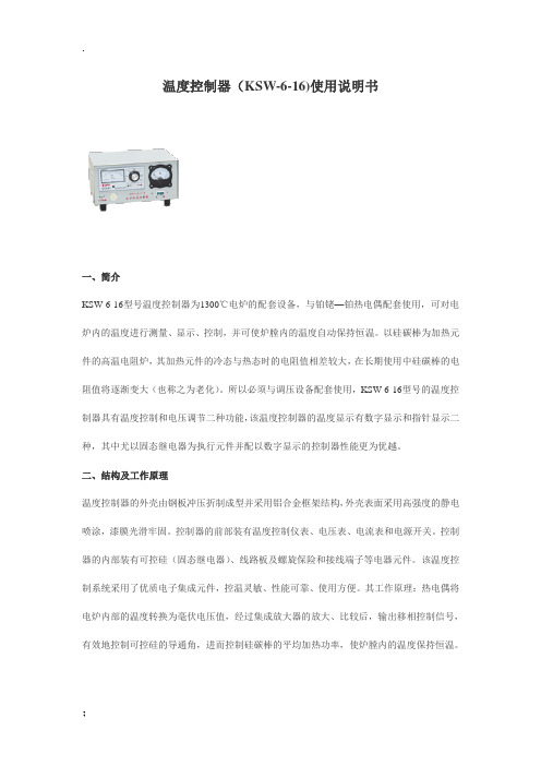
温度控制器(KSW-6-16)使用说明书一、简介KSW-6-16型号温度控制器为1300℃电炉的配套设备,与铂铑—铂热电偶配套使用,可对电炉内的温度进行测量、显示、控制,并可使炉膛内的温度自动保持恒温。
以硅碳棒为加热元件的高温电阻炉,其加热元件的冷态与热态时的电阻值相差较大,在长期使用中硅碳棒的电阻值将逐渐变大(也称之为老化)。
所以必须与调压设备配套使用,KSW-6-16型号的温度控制器具有温度控制和电压调节二种功能,该温度控制器的温度显示有数字显示和指针显示二种,其中尤以固态继电器为执行元件并配以数字显示的控制器性能更为优越。
二、结构及工作原理温度控制器的外壳由钢板冲压折制成型并采用铝合金框架结构,外壳表面采用高强度的静电喷涂,漆膜光滑牢固。
控制器的前部装有温度控制仪表、电压表、电流表和电源开关。
控制器的内部装有可控硅(固态继电器)、线路板及螺旋保险和接线端子等电器元件。
该温度控制系统采用了优质电子集成元件,控温灵敏、性能可靠、使用方便。
其工作原理:热电偶将电炉内部的温度转换为毫伏电压值,经过集成放大器的放大、比较后,输出移相控制信号,有效地控制可控硅的导通角,进而控制硅碳棒的平均加热功率,使炉膛内的温度保持恒温。
三、设备的安装及使用3.1 设备安装前应将电炉温度控制器放在平整的工作台上,先进行外观的检查:外观应无破损,仪表外观应完好,电源开关完好,使用说明书、合格证齐全。
安装使用前应仔细阅读产品使用说明书并按其要求进行安装与操作。
3.2 指针式温度控制仪表的设定与使用:指针式温度控制仪表应先观察仪表指针是否指在零位,如不在零位,可左右轻微地调节仪表的机械调零螺钉,使之对正即可。
根据不同的工作温度,将设定温度旋钮上的白色标记指到相应的温度上。
红灯亮表示停止加热,绿灯亮表示加热,红绿灯交替亮灭表示进入时间比例加热段或恒温段。
该仪表最高控制温度为1600℃。
3.3 数字式温度控制仪表设定与使用:数字式温度控制仪表不需要调零,将测量/设定开关拨到设定位置后,旋转设定旋钮,温控仪表显示的数字即设定的工作温度。
温控器说明书
温湿度控制器一、产品概述温湿度控制器,主要应用于需要对被测环境进行自动温湿度调节的场合,用户可通过按键分别调整温湿度的上、下限值来控制加热或排风实现自动控制,显示方式为数码管显示。
二、基本功能:2.1 温度测量范围:-25℃~+80℃±1℃;2.2 湿度测量范围:相对湿度RH: 0%~99% 精度±3%RH;2.3 控制方式:温度采用上、下限和回差控制,湿度采用上、下限控制,所有参数均可设置;2.4 输出控制类型:两组继电器触点,分别为加热和排风,每路最大负载AC250V /3A,均为有源输出。
三、技术指标:3.1电源:AC 220V±20%3.2 工作环境:温度:-25℃~+55℃,相对湿度:<95%RH3.3控制设定范围:温度:0℃~80℃,相对湿度:50%RH~99%RH3.4 本机功耗:<3W3.5自检功能:若数码管显示“–––”,则为检测到传感器故障;若加热或排风运行过程中相应指示灯熄灭,则检测到加热或排风故障。
四、工作原理:4.1 温度控制:当被测环境温度低于设定温度下限时,本仪器启动电加热设备开始加温,此时加热指示灯亮,温度升至比下限温度设定值高回差值时,即:W测≥W下限+回差,停止加温。
当被测环境温度高于设定温度上限时,本仪器启动降温设备(如风机或空调)开始降温,此时排风指示灯亮,温度降至比上限温度设定值低回差值时,即:W测≤W上限-回差,停止降温。
4.2 湿度控制:当被测环境湿度超过设定湿度上限时。
如果当前温度较高,即:W测≥W下限+(W上限-W下限)×3÷4,采用降温(或排风,视具体地区采用不同设备)抽湿,此时排风指示灯亮;抽湿过程中,如果温度低于下限温度+2度后,自动转为加热降湿;当降湿过程中温度高于上限温度-2度后,自动转为降温抽湿,直至湿度低于设定下限值为止。
当被测环境湿度超过设定湿度上限时。
如果当前温度较低,即:W测<W下限+(W上限-W下限)×3÷4,采用加热降湿,此时加热指示灯亮,降湿过程中,如果温度高于上限温度-2度后,自动转为降温抽湿;当温度低于下限温度+2度后,自动转为加热降湿,直至湿度低于设定下限值为止。
3WIA-0B2700-030壁挂式 外气式温控器说明书
感謝您購買本公司的產品!為使產品能正常運作,請您詳閱使用手冊,並請依照說明操作。
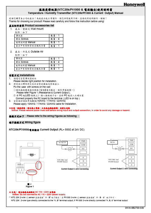
謝謝!Thanks for choosing our product! Please read carefully and follow this instruction before using!產品附件清單 Product accessories list 1. 產品:壁掛式 Wall mount附件:如下 傳訊器 數量:1 螺絲 Screws 數量:4 使用說明書 Manual 數量:1 產品中有害物質的名稱及含量 數量:12. 產品:外氣式Outside Air 附件:如下傳訊器數量:1螺絲Screws數量:4 使用說明書Manual數量:1 產品中有害物質的名稱及含量數量:1安裝方式Installations1. 請選定安裝傳訊器的位Please decide right position for installation. 2. 將底座以螺絲固定在欲安裝的牆面或裝線盒上Fix the b ase with screws on the wall○1請依接線圖連接訊號線 (電阻&電流輸出,請參考接線圖一) Please refer Figure 1 (Resistance & Current Output ).○2 將PC 板(LED 面朝上),插入接線端子台,並將PC 板崁入正確位置 Connect properly the PC board to the terminal ( LED is on top ) 3. 安裝線材請採用隔離線(15AWG / 17AWG / 22AWG)Please apply 15AWG / 17AWG / 22AWG cable for installation.*注意:接線前後,請勿接上電源,以免造成機板損壞,或發生危險Notice: Please remove power from unit before wiring input and output connection, in order to avoid any damage or hazard.接線方式如下:Please refer to the wiring Figures as following :端子接線方式Wiring figureNTC20k/Pt1000&電流輸出 Current Output (RL< 500Ω at 24V DC)圖一 Figure 1* 注意: 請勿接線或碰觸到AC 110 ~ 220V 的電源Notice: Do not connect to AC 110 ~ 220V power supply.** NTC 20K 2-wire 式sensor 直接連接”A ,B ” 端子輸出;若Pt1000 3-wire 式sensor 直接連接”A ,B ,b ”端子即可。
[方案]温控阀说明书2
![[方案]温控阀说明书2](https://img.taocdn.com/s3/m/447ff239b5daa58da0116c175f0e7cd184251822.png)
eEAST-WKS2系列室内恒温控制器使用说明书一、产品图片及描述EAST-WKS2系列室内恒温控制器是一款大屏幕液晶显示温控器,主要用于水采暖系统。
造型精美、性能可靠、操作简单。
采用微型处理器,运用人工智能的模糊逻辑控制,LCD大液晶显示,设备的运行状态及环境温度一目了然。
通过设定房间所需温度,温控器根据所设定的温度自动开启和关闭阀门,从而达到调节房间温度的目的,让温度控制更加方便、高效、舒适、节能。
二、功能介绍◆室内温度设定、测量并显示◆掉电设定数据存储功能◆睡眠功能◆时钟12/24小时显示、星期显示,掉电记忆◆四时段温度编程可控功能◆低温保护◆背光功能◆温度校准三、技术参数指标◆温度传感器:热敏电阻◆电源电压:DC +5V,2A◆设定温度范围:0.5~30.0℃(内置传感器)◆电路负载:2A阻性◆测量精度:±1℃◆自耗功率:<2W◆显示精度:±0.5℃◆外壳:PC+ABS阻燃◆显示方式:LCD ◆防护等级:IP30◆背景:蓝色或白色半透背光◆外形尺寸:88×88×22mm◆工作环境:0~45℃◆安装孔距:标准86盒四、操作说明★开/关机:长按“”键关机,液晶屏不显示;再长按此键直至液晶屏显示,开机。
★工作状态选择:温控器有4种工作状态,分别是实时模式“”、睡眠模式“”、防冻模式“”和编程模式“”,可通过按“”键切换,当选择到所需模式时,模式图标闪烁,长按“”键,直到图标不闪烁,启动所选择的模式。
◆实时模式:该模式可通过实时设置温度来调节室内温度。
当开机后,系统默认为实时模式,按一次“”设置温度闪烁,按“↑”键升高设置温度,按“↓”键降低设置温度,每按键一次设置温度变化0.5℃,设置完毕后,按一次“”,返回到初始界面。
◆睡眠模式:该模式是在晚上睡眠的时候,温控器自动运行的一种模式。
这种模式可以减少环境温度与设置温度的差值,让电动球阀容易停机,达到省电目的。
HONEYWELL温控器HCE60

StoreyControllerHCE 60 Mounting and OperationOverview C ONTENTSOverview3 Application3 Procedure during the installation4 Assigning zones and actuators4 Mounting4 Configuration and installation4 Configuration4 Creating a zone plan5 Specifying temperature zones5 Filling out the zone plan6 Mounting9 Wall mounting10 DIN rail mounting11 Mounting the Hometronic heating components11 Configuration and installation12 Opening the housing13 Cabling connections15 Configuration24 Preparing the configuration24 LED display at the storey controller26 Operating modes of the storey controller27 Buttons281OverviewAssigning zones and room names29 Example: Assigning an HCW 22 setpoint adjuster to Zone 130 Example: Assigning the room name LIVING to Zone 131 Assigning a remote setpoint adjuster HCU 30 to a temperature zone33 Assigning a setpoint adjuster of type HCW 23 to a zone33 Reversing the assignment34 De-installing room names at the Hometronic Manager35 Saving settings at the Hometronic Manager36 Checking the configuration36 Checking the radio transmission37 Checking the assignment of the room names37 Displaying faults38 Terminating the configuration39 Resetting the storey controller to the state of delivery40 Appendix41 Glossary41 Help for problems42 Overview of the Hometronic heating components45 Zone plan46 2Overview OverviewFor your informationTechnical terms are explained in the glossary (page 41). They are identified in the text by an *.ApplicationThe storey controller HCE 60 receives specifications for the room temperature from the setpoint adjusters* and the Hometronic Manager*. The storey controller controls the boiler regression*, the pump relay and the thermal actuators* (refer to page 45, Hometronic heating components) on the basis of these specifications.It disposes of a self-teaching control function (fuzzy logic) which adapts itself automatically to the environmental conditions. The desired room temperature is reached rapidly and held constant.In order to provide a rapid overview of the display and operation there is a sticker on the rear of the instructions which can be stuck onto the housing of the storey controller.3Overview 4Procedure during the installationAssigning zones and actuators• Specify which heating circuits* are controlled by the storey controller.Mounting• Mount the Hometronic heating components.Configuration and installation• Set the storey controller to the actuator type, cable the connections and interconnect the components.Configuration• Assign setpoint adjusters to the temperature zones.• If appropriate, assign room names at the Hometronic Manager.• If appropriate, assign the time program of the remote setpoint adjuster HCU 30 to the temperature zones.Creating a zone plan 5Creating a zone plan*A temperature zone is an area of the building – e.g. a room – in which the setpoint temperature* is set by means of a setpoint adjuster. The storey controller controls all the thermal actuators of a temperature zone to the same value.5 temperature zones can be set up per storey controller. The extension module HCS 60 increases the number of temperature zones per storey controller to 8. A maximum of 3 actuators can be connected in each zone.The total number of actuators which can be controlled by one storey controller is thus limited to 24.Specifying temperature zonesCaution Danger of damage through external equipment! The storey controller is designed only for components which have been authorized by Honeywell!► Only use actuators of the type H 200 BG (no-load closed) or H 200 BO (no-load open).► Combine all the actuators (type and location) which are managed by the storey controller.► Combine all the actuators which are controlled by a setpoint adjuster in a temperature zone.Creating a zone plan 6In case of more than 8 temperature zones or 24 actuators:► Determine the number of storey controllers required additionally in accordance with the following table:Temperature zones (maximum)Actuators (maximum)Number of storey controllers82411648224723T he example at the end of this section shows a zone division with the corresponding zone plan.Filling out the zone plan► Copy the sample zone plan (see Appendix page 45) as a reserve.► Enter the type and installation location of the corresponding actuator in each temperature zone.► Assign a setpoint adjuster to every temperature zone.► If appropriate, assign a room name.► After the installation hand the zone plan over to the customer.Creating a zone plan 7• The living area is covered by 6 temperature zones. The supplementary module HCS 60 is required for this subdivision .• A total of 8 actuators are controlled by the storey controller.Up to 8 temperature zones can be controlled with the supplementary module HCS 60. The planned temperature zones are grayed.T he room names of every temperature zone are entered at the Hometronic Manager.Creating a zone plan 8The following zones result for the subdivision:Temperature zone Actuator (type, location)Setpoint adjuster (location)Room name at HCM 200Heating loop 1(living room)Living room"Living"Zone1Heating loop 2(living room)Heating loop 3(living room)Zone2Heating loop 1(dining room)Dining room"Dining"Zone3Heating loop 1(kitchen)Kitchen"Kitchen"Zone4Heating loop 1(bedroom)Bedroom"Bedroom"Zone5Heating loop 1(WC)WC"WC"Zone6Heating loop 1(bathroom)Bathroom"Bath"Mounting MountingC aution!T he storey controller has a radio receiver whose function can be impaired by metallic objects and radio devices!►When selecting the operating site ensure that there is sufficient distance to metallic objects and radio devices.►If the radio interference cannot be eliminated select a different mounting site.The storey controller is intended to be mounted in the distribution box. If the space is insufficient, select the location so that the storey controller can communicate without interference by radio with the setpoint adjusters against humidity and moisture.The storey controller can be fastened by 2 means:• Wall mounting• DIN rail mountingMountingWall mountingThe storey controller has 4 mounting holes with a diameter of 4.2 mm.O bserve the mounting height of 60 mm of the storey con-troller! If the storey controller is mounted upright, the trans-former has to be at the top so that the heat can dissipate.►Draw, drill and dowel the fastening holes.►Screw the storey controller.Mounting DIN rail mounting►Place the housing frombelow against the DIN rail(1).►Press the housing upwardsand latch it in (2).Mounting the Hometronic heating components►Mount the components in accordance with the enclosed mounting instructions.Configuration and installationDanger D anger to life through electric shock!E lectrical contacts (outputs of the actuators, power fuse and transformer) which are live lie free while the device is being cabled. Touching a live contact causes critical injuries.►All work may only be carried out by authorized specialized personnel.►Pull out the power plug before opening the housing.C aution!D amage to components lying open!T he electronic components of the storey controller and of the plug-in module can be destroyed by electrostatic discharges!►Do not touch the components.►Touch a grounded metal part in order to discharge yourself.Configuration and installation Opening the housing►Loosen the screw at thefront (1).►Press both snaps inwards(2).►Remove the housing coverupwards (3).Plugging in the extension module (optional)The extension module HCS 60 increases the possible number of►Plug the extension moduleinto the provided slot.Configuration and installationSetting the actuatorO nly one type of actuators can be connected at a storey controller. If both no-load open and no-load closed actuators are to be operated, two storey controllers with the respective control system are required.1. Switch for configuration(O = Open, C = Closed)2. Setpoint temperatureceramic fuse (type:230 V AC; 2.5 A, fast;5×20 mm)T he actuators are protected by the ceramic fuse.►Check which type the actuator is.►Set the switch in accordance with the following table.Configuration and installationCabling connectionsPermitted cable types and lengthsCable (designation)Connection betweenstorey controller HCE 60and Maximum permitted lengthJE-LiYCY 2×2×0.8Setpoint adjuster HCW 23100 m CY 2×2×0.14Setpoint adjuster HCW 23100 m JE-Y(St)Y 2×2×0.8Setpoint adjuster HCW 23100 mMCR precontrol100 mPump relay HREL1100 m 1.5 mm2Thermal actuatorsH200 BO and H200 BG100 mCable harness Thermal actuatorsH200 BO and H200 BG 1 m (3 m)Cable harness Antenna HRA1 1.2 mConfiguration and installationO nly use cables with cable cross-section areas up to 1.5mm2. We recommend the cable type JE-Y(St)Y 2×2×0.8. Usethe enclosed connector types and sufficiently long cable.1. Connectors (1...12)2. Connections for extensionmodule HCS 603. Antenna connector4. Connectors of theactuators for Zone 1 to 8.Up to 3 actuators can be connected to Zone 1, only one actuator at all other zones.T he cable harness of the thermal actuators can be extendedfrom 1 m to 3 m. This cable is available with integral plug astype HCV 2.Configuration and installationDanger D anger to life through electric shock!E lectrical contacts (outputs of the actuators, power fuse and transformer) which are live lie free while the device is being cabled. Touching a live contact causes critical injuries.►All work may only be carried out by authorized specialized personnel.3 actuators can be connected for Zone 1, 1 actuator each for Zones 2 to 5. 1 connection each is available for Zones 6 to 8 for the extension module.If more than 8 actuators are to be connected to the storey controller, the cables of the actuators have to be wired in a distribution box.The storey controller can control up to 24 actuators. However, a maximum of 3 actuators per zone can be connected.T he cable harness of the actuators can be extended from 1 mto 3 m. This cable is available with integral plug astype HCV 2.►Lay the cables of the actuators to the distribution box.►Wire the conductors of the actuators.►Use the cable HCV 2 to extend the cable to the storey controllerConfiguration and installation►Insert the plugs of the actuatorconnecting cables into the sockets of the corresponding zones.►Clamp the cables in the strain relief device.►Use a diagonal cutter to break out openings at the housing for the cables.Configuration and installation Connecting a setpoint adjuster HCW 23Through their wiring the setpoint adjusters of type HCW 23 have a fixed assignment to the Zones 1 and 2.I f the remote controller HCW 23 is removed, the assignmenthas to be removed as well. Refer to "Reversing theassignment" on page 34.►Use cables in accordance with the table on page 15.►Connect the connectors of the setpoint adjusters to the connectors of the storey controller.1. Setpoint adjuster 12. Setpoint adjuster 23. Zone 14. Zone 25. Bus (not activated)6. Boiler regression7. Pump relay HREL 1TW Input temperatureselectorRF Input room sensor⊥GroundConfiguration and installationConnecting the boiler regression and pump relayBoiler regression is possible at the controllers MCR 200, MCR 35 and MCR 40 :At the MCR 200 controller the temperature selection and ground input lie at different terminals, depending on the respective design.►Connect the inputs in accordance with the enclosed instructions.At the controllers MCR 35 and MCR 40 the temperature selection and ground input lie at the following terminals:Configuration and installation Boiler regressionIf control cables to the heating ("boiler regression“) and to the pump relay exist:►Use cables in accordance with the table on page 15.►Connect the boiler regression and the pump relay to the storey controller in accordance with the following scheme:Configuration and installation Installing the antennaA n antenna has to be connected to each storey controller!Take the antenna function into consideration when selectingthe operation site.►Install the antenna (1) outsidemetal housings, e.g. switchcabinets (4).►Do not extend the antennacable.►Mount the antenna at a suit-able position near the storeycontroller (3).The radio connection to the set-point adjuster (2) has to be en-sured.►Plug the antenna cable into the antenna socket of the storey controller.Closing the housing of the storey controller►Place the lid on the housing.►Snap in the snaps on the left and right.►Tighten the screw at the front.ConfigurationConfigurationDuring configuration setpoint adjusters – if appropriate the time program* of the remote setpoint adjuster HCU 30 – are assigned to the temperature zones of the storey controller. A room name is specified for each temperature zone at the Hometronic Manager. Preparing the configuration►Set the adjusting dial toPosition 0.Opening the housing:►Press in the snap (1) andremove the housing lid (2).Configuration►Insert 2 Mignon batteriesLR06 each 1.5 Volt.►Ensure that the polarity iscorrect.1)Sending button(required for configuration).Commissioning the storey controller►Plug in the power plug.The LED for the mains voltage lights up.Taking the setpoint adjuster HCU 30 into operation►Refer to the instructions for the setpoint adjuster HCU 30.Taking the room temperature sensor HCF 22 into operation►Refer to the instructions for the room temperature sensor HCF 22.ConfigurationLED display at the storey controllerThe LEDs of the storey controller provides information on the operating modes of the storey controller and the installed temperature zones.Meaning of the 3 LEDs on the left:Flashes Device displayThe LEDs 1..8 are assigned to the temperature zones and can light up green, yellow and red. The meaning of the colors depend on the selected operating mode.Configuration Operating modes of the storey controllerNormal modeIn normal mode the LEDs 1..8 provide information on the position of the actuators:Green Thermal actuator openedOff Thermal actuator closedFault modeIn fault mode the status displays provide information on a fault in the individual temperature zones.Refer to the section "Displaying faults" on page 37.Installation modeIn installation mode you assign temperature zones to the setpoint adjusters and the Hometronic Manager.Refer to the section "Example: Assigning an HCW 22 setpoint adjuster to Zone 1" on page 30.Device displayThe device display informs you on the configuration of your Home-tronic System, i.e. about the assignment of setpoint adjusters to the temperature zones of room names at the Hometronic Manager. Refer to the section "Checking the configuration" on page 36.ConfigurationButtons• FaultWhen the fault button is pressed, the storey controller changes to the fault display. Refer to the section "Displaying faults" on page 37.• Installation button:When the installation button is pressed, the storey controller changes to installation mode or to the device display.Assigning zones and room namesThe following section describes how setpoint adjusters and room temperature sensors are assigned to a temperature zone. The procedure is identical for both device types and is therefore only explained on the basis of the setpoint adjuster.Example: Assigning an HCW 22 setpoint adjuster to Zone 1 In the following example the setpoint adjuster HCW 22 is assigned to Zone 1.Subsequently the room name "Living" is assigned to Zone 1 in the►►seconds.of Zone 1 flashes red.The storey controller is in instal-lation mode and waits for thesignal of a setpoint adjuster.n order to assign a setpoint adjuster to a different zone, pressuntil the LED of the desired zone ►Press the send button of the setpoint adjuster.The LED of the selected zone lights continuously red.I f no Hometronic Manager is installed, the storey controlleroperates with a basic value of 20 °C. For information on howthe configuration is checked please refer to page 36.►The LED of the selected zone flashes green. The storey controller waits for a signal from the Hometronic Manager. The standard text is displayed at the Hometronic Manager (example):HOMETRONICWE 29.10.1999 11:15 no lifestyle active LIVING 20.0 C►Press the Dial button.The following text is displayed:MENUSET DATE/TIME ACTIVATE LIFESTYLE LIVING 20.0 C►Turn the Dial button to the right until "Menu" is selected.MENUSET DATE/TIME ACTIVATE LIFESTYLE LIVING 20.0 C►Press the Dial button.The following text is displayed:LIFESTYLES TIME PROGRAMS SETTINGS VERSION►Select the "Settings" submenu and press the Dial button.The following text is displayed:INSTALLATIONDE-INSTALLATION FUNCTION EXTENSION SENSOR FUNCTION►Select the "Installation" submenu and press the Dial button.The following text is displayed:HEATING SHUTTERS DEVICES/LIGHT SENSOR►Select the "Heating" submenu and press the Dial button.A list of the room names (possibletemperature zones) is displayed:LIVING DINING KITCHEN BEDROOM►Turn the Dial button at the Hometronic Manager until "Living" is selected an press the Dial button.An * is displayed..LIVING * DININGKITCHENBEDROOMThe LED of Zone 1 at the storey controller flashes green. The room name is assigned to the temperature zone 1.►Enter the room name in the zone plan.►Repeat the steps until a room name is assigned to all the temperature zones.►The storey controller is back in normal mode.I f the installation button is not pressed for longer than 4minutes, the storey controller changes to normal mode.The assigned temperature zones remain stored in the storeycontroller, even after a power failure.Assigning a remote setpoint adjuster HCU 30 to a tempe-rature zoneThe operating instructions of the remote setpoint adjuster describe how to assign the remote setpoint adjuster HCU 30 to a temperature zone.Assigning a setpoint adjuster of type HCW 23 to a zone Through their wiring the setpoint adjusters of type HCW 23 have a fixed assignment to the Zones 1 and 2.I f the remote controller HCW 23 is removed, the assignmenthas to be removed as well. Refer to "Reversing theassignment" on page 34.Reversing the assignmentReverse the assignment of the setpoint adjuster to the tempe-rature zone►►►until the LED of the temperature zone extinguishes.The assignment of the setpoint adjuster for the temperature zone is reversed.Reversing the assignment of the room name or time program to the temperature zone►►until the LED of the temperature zone extinguishes.The assignment of the room name or of the time program for the temperature zone is reversed.De-installing room names at the Hometronic Manager ►Change to the "Settings" submenu as described on page 31. The following text is displayed:INSTALLATIONDE-INSTALLATIONFUNCTION EXTENSIONSENSOR FUNCTION►Select the "De-installation" submenu and press the Dial button.The following text is displayed:HEATING SHUTTERS DEVICES/LIGHT SENSOR►Select the "Heating" submenu and press the Dial button.A list of the assigned room names(temperature zones) is displayed:LIVING * DINING * KITCHEN * BEDROOM *►Select the room name (here Living) and press the Dial button.The * symbol behind the room name disappears in the display:LIVINGDINING * KITCHEN * BEDROOM *The assignment is deleted and can be carried out again.Saving settings at the Hometronic ManagerBefore configuration is terminated the settings have to be saved at the Hometronic Manager.For information on saving the settings please refer to the "Adapting" chapter in the operating instructions of the Hometronic Managers.►The storey controller is in the device display.The colors of the LED 1...8 now provides information on the configuration of the temperature zones.Off No device installedRed Setpoint adjuster is installedGreen Hometronic Manager or remote setpoint adjuster HCU 30 is installedYellow The setpoint adjuster and Hometronic Manager areinstalledChecking the radio transmission►Press the send button at the setpoint adjuster.The LED 1..8 of the assigned zone flashes red. The radio transmission is established.Checking the assignment of the room names►Change the setpoint temperature at the Hometronic Manager (refer to the Hometronic Manager instructions)The LED 1..8 of the assigned zone flashes green. The assignment is correct.The storey controller terminates the device display after approx. 60 seconds and changes back to normal mode.zone.►display.The colors of the LED 1...8 now provides information on a fault in the temperature zones.Off No faultRed Cable break / no connection to the setpoint adjusterGreen No connection to the Hometronic Manager or remotesetpoint adjuster HCU 30Orange No connection to the setpoint adjuster and Hometronic ManagerThe storey controller terminates the fault display after approx. 60 seconds and changes back to normal mode.Assigning zones and room names39Terminating the configurationClosing the setpoint adjusters► Put on the lid and latch in at both snaps.Handing out the zone plan► Pass on the filled out zone plans together with the mounting instructions to the customer. Both documents are important if changes are to be carried out later at the system.Assigning zones and room names40Resetting the storey controller to the state of deliveryA ll current assignments are lost if the storey controller is reset to the state of delivery. The storey controller retains its confi-guration after a power failure.►►►The LED of Zone 1 is extinguished. The LED of Zone 2 is illuminated.► ► Pull the plug of the storey controller again and plug it in again.The storey controller is reset to the state of rmation for the fitterAfter the storey controller has been configured you should inform your customer about the Hometronic System.► Familiarize your customer with the operation of the Hometronic.► Explain the manual operation of the components.► Point out particular features and extension possibilities of the re-spective customer installation.Appendix41AppendixGlossarySetpoint adjusterDetects the actual temperature,changes the setpoint tempe-rature. Is mounted in every zone at a user-friendly location Heating circuitArea which is controlled by a setpoint adjuster.Hometronic ManagerCentral operating device of the Hometronic System Boiler regressionHometronic controls the heating boiler via an analog control device of Honeywell.Setpoint temperatureRoom temperature which is to be reachedThermal actuatorOpens and closes a heating circuit. Is controlled by the storey controller.Time programDefined combination of setpoints and switching points at the Hometronic Manager.Zone planOverview of the temperature zones of the storey controller.Appendix42Appendix43Appendix44AppendixOverview of the Hometronic heating componentsA Setpoint adjuster HCW 22Controls the setpoint temperature per temperature zoneB Remote setpoint adjuster HCU 30Controls the setpoint temperature per temperature zone via thesetpoint adjuster. Defines the time programs for the comfort andeconomy temperaturesC Room temperature sensor for storey controller HCF 22Transfer the room temperature to the story controllerD Hometronic ManagerCentral operating device of the home automation systemE Setpoint adjuster HCW 23 (wired)Controls the setpoint temperature per temperature zone via thesetpoint adjusterF Story controller HCE 60Controls the actuators of the floor heatings/radiators. Communi-cates with setpoint adjusters and room temperature sensorsG AntennaH Boiler regression HS 30I Pump relayJ Thermal actuators45Appendix46Zone planZone Actuator(type, location)Setpoint adjuster (location)Room name12345Appendix47Limitations at the configuration• Maximum of 5 (8) zones per story controller • Maximum of 3 connections per zone• Maximum of 24 actuators per story controller• Only one type of thermal actuators per story controller (no-load open or no-load closed)• Either heating loops (underfloor heaters) or radiators.Honeywell AGBöblinger Straße 17D – 71101 SchönaichTelephone (+49) 7031 637-300This company is certificated toThe right is reserved to make modifications. This document is definitive for the enclosed product and replaces all previous publications.No. 7157521EN1H-0134 GE51R0301。