RIPv2配置实例
实验24 RIPv2 验证的配置

实验24 RIPv2 验证的配置
【背景知识】
教材5.4.5内容。
理解RIPv2的验证原理,掌握RIPv2的验证配置方法。
【实验拓扑】
实验线路连接图8-32所示,实验时使用GNS模拟器完成拓扑结构搭建。
GNS 是一款比Cisco Packet Tracer 5.2更为强大的模拟软件,详细的使用说明见教材附录2。
图8-32 实验24线路连接图
【实验内容】
(1) 在GNS3 模拟器环境中,添加两台C3620 路由器,关闭电源后分别添加NM-4T 模块,添加位置为插槽1,然后手工添加两台路由器之间Serial 接口连接,启动路由器。
分别选择路由器R1 和R2,鼠标右键选择Console 进行带外管理。
(2) 分别在各台路由器上完成Serial 接口和Loopback 接口IP 地址配置,并且路由器之间相互ping 通。
Serial 接口可使用默认HDLC 封装,即不需要进行封装的配置。
(3) 参阅教材5.4.5中内容,首先在各台路由器上配置RIP验证和RIP路由协议,要求RIP版本为2、无自动汇总、RIP 验证为明文。
(4) 在各台路由器上使用show ip route查看路由表,查看是否学习到对端路由器的路由信息。
若没有学习到,查看RIP验证配置是否正确。
(5) 完成以上配置内容后,改用RIP密文验证的配置,并查看路由表是否学习到对端路由器。
【实验问题】
1.RIPv2的验证过程是怎么样的?
2.比较GNS与Cisco Packet Tracer5.2的优缺点。
【实验报告】
截屏命令行输出并回答实验问题。
《RIPv2的配置、认证和汇总》

R1:
R2:
用debug ip rip查看验证结果:
实验内容与步骤
MD5验证:
R2:
R3:
debug ip rip查看验证:
测试网络的连通性:、
网络通畅!
4.在R1上手工汇总4个环回地址。
R1汇总前R3上的路由表:
R1汇总后R3上的路由表:
第三页
实验内容与步骤
从R3上ping172.16.0.1:
网络畅通!
实验总结
通过此次实验,我掌握了RIPv2的基本配置;RIPv2的明文和密文认证;RIPv2的自动汇总和手工汇总。
教师评定
签字:年月日
2014学年学期第一页实验题目实验6ripv2的配置认证和汇总实验目的1掌握ripv2的基本配置
2013 —— 2014学年第二学期
第一页
实验题目
实验6RIPv2的配置、认证和汇总
实验目的
1、掌握RIPv2的基本配置;
2、掌握RIPv2的明文和密文认证;
3、掌握RIPv2的自动汇总和手工汇总;
实验内容与步骤
一、实验拓扑图及相关接口的ip
二、实验步骤
1.路由器的基本设置:
R1:2协议并关闭自动汇总。
R1:
R2:
R3:
第二页
实验内容与步骤
测试网络:
R1 ping 172.16.4.1
R1 ping 172.16.4.1 source 172.16.0.1
3.在各个路由之间配置认证,R1和R2间采用明文验证,R2和R3间采用MD5认证,并用命令debug ip rip查看验证。
实验8 基本的RIP V2配置

实验名称基本的RIP V2配置。
实验目的掌握在路由器和三层交换机上配置RIP V2。
实现功能通过RIP2协议实现网络的互连互通,从而实现信息的共享和传递。
实验设备锐捷R2624路由器2台,网线2根,V35线缆1对。
背景描述一个公司总部和销售公司分处在两个地方,现为了搭建公司的OA系统,需要将两地的网络连在一起。
本实验以两台R2624路由器为例来模拟该环境,路由器1和2通过V35线缆连接。
PC1连着Router1,PC2连着Router2.PC1的网络地址为192.168.11.0/24,两个路由器的串口地址为192.168.12.0/24,PC2的网络地址为192.168.13.0/24.实验步骤1.对Router1进行基本配置:configure terminalhostname Router1interface fa1/0ip address 192.168.11.1 255.255.255.0no shutdowninterface S1/2ip address 192.168.12.1 255.255.255.0clock rate 64000no shutdownexitshow ip interface brief2.对Router2进行基本配置:configure terminalhostname Router2interface fa1/0ip address 192.168.13.1 255.255.255.0no shutdowninterface S1/2ip address 192.168.12.2 255.255.255.0no shutdownexitshow ip interface brief3.对Router1配置路由协议rip2:Configure terminalRouter rip(开启RIP路由协议)Version 2(定义RIP路由协议的版本为2)Network 192.168.11.0(定义与本路由器相连的关联网络)Network 192.168.12.0(定义与本路由器相连的关联网络)EndShow ip route(显示路由表)4.对Router2配置路由协议rip2:Configure terminalRouter ripVersion 2Network 192.168.12.0Network 192.168.13.0EndShow ip route5.测试网络的连通性,将两台计算机的IP地址设为所属网段的地址,网关设为所连路由器的以太网口的地址。
RIPv2 基本配置实验
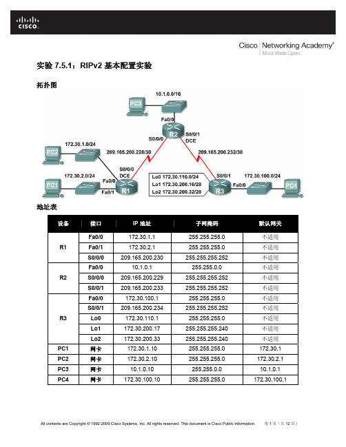
CCNA Exploration 路由协议和概念:RIPv2
步骤 3:将以下脚本加载到 R3。
hostname R3 ! ! ! interface FastEthernet0/0
ip address 172.30.100.1 255.255.255.0 duplex auto speed auto no shutdown ! interface Serial0/0/1 ip address 209.165.200.234 255.255.255.252 no shutdown ! interface Loopback0 ip address 172.30.110.1 255.255.255.0 ! interface Loopback1 ip address 172.30.200.17 255.255.255.240 ! interface Loopback2 ip address 172.30.200.33 255.255.255.240 ! router rip passive-interface FastEthernet0/0 network 172.30.0.0 network 209.165.200.0 ! line con 0 line vty 0 4 login ! end
up
Serial0/0/1
209.165.200.233 YES manual up
up
Vlan1
unassigned
YES manual administratively down down
All contents are Copyright © 1992-2009 Cisco Systems, Inc. All rights reserved. This document is Cisco Public Information. 第 4 页(共 12 页)
实验23 RIPv2的配置
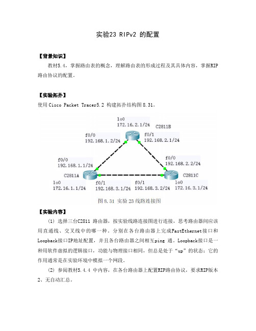
实验23 RIPv2 的配置【背景知识】教材5.4,掌握路由表的概念,理解路由表的形成过程及其具体内容,掌握RIP 路由协议的配置。
【实验拓扑】使用Cisco Packet Tracer5.2 构建拓扑结构图8.31。
【实验内容】(1) 选择三台C2811 路由器,按实验线路连接图进行连接,思考路由器间应该用直通线、交叉线中的哪一种。
分别在各台路由器上完成FastEthernet接口和Loopback接口IP地址配置,并且各台路由器之间相互ping 通。
Loopback接口是一种用软件虚拟的逻辑接口,功能与物理接口相同,但总是处于“up”的状态;它的作用通常是在实验环境中模拟一个网段。
(2) 参阅教材5.4.4 中内容,在各台路由器上配置RIP路由协议,要求RIP版本2、无自动汇总。
(3) 在各台路由器上使用show ip route查看路由表,详细理解路由表的内容。
在各台路由器上使用show ip protocol查看路由协议RIP运行情况。
【实验问题】1.关闭C2811A的f0/1端口,观察路由器C2811A、C2811B、C2811C路由表的变化。
可以用debug ip rip查看路由信息交互过程,若需关闭可以用undebug all(简写u all)命令。
2.用Show ip route查看路由表,解释路由条目各信息的含义,尤其是要解释其中的路由更新时间的含义。
3.在路由器C2811A上用show ip route查看路由表,可以发现到达192.168.2.0网段有2条路由,为什么?如何路由器C2811A在转发数据包时,如何使用这2条路由?【实验报告】截屏命令行输出并回答实验问题。
实验9 动态路由(RIPV2)

动态路由(RIP V2)的配置一.实验目的和要求掌握在路由器上配置RIP V2二.实验环境计算机网络实验室提供进行正常的网络实验设备和相应的软件环境。
实验室有24套计算机设备,接入路由器12台,接入交换机12台以及与各种网络实验相关的配件资料和设施,可满足20-30人同时进行网络实验的需求。
三.实验的内容和要求1.常用命令模式掌握路由器命令模式间的进出2.动态路由的配置方法掌握动态态路由的配置步骤3.RIP协议的作用深刻理解RIP的作用及其工作原理四.实验设备:1.2台R26242.计算机(至少2台)3.标准网线若干、V35DTE线缆(1根)、V35DCE线缆(1根)五.实验步骤1.实验拓扑(V35DCE端联RA)R2624-A>enable !进入特权模式R2624-A#config terminal !进入全局配置模式R2624-A(config)#interface fastethernet0 !进入路由器接口配置模式R2624-A(config-if)#ip address 172.16.10.1 255.255.255.0 !配置接口F0的IP地址R2624-A(config-if)#no shutdown !开启路由器fastethernet0接口R2624-A(config)#end !返回进入特权模式3. 在路由器RA上配置广域网口的IP地址和时钟频率R2624-A#config terminalR2624-A(config)#interface serial 0 !进入接口S0配置模式R2624-A(config-if)#ip address 172.16.80.1 255.255.255.0R2624-A(config-if)#clock rate 64000R2624-A(config-if)#no shutdownR2624-A(config-if)# end4. 在RA上配置动态路由R2624-A#config terminalR2624-A(config)#router rip !配置动态路由R2624-A(config)#Version 2 !定义版本2R2624-A(config-router)#network 172.16.0.0 !定义直连网络5. 在路由器RB上配置快速以太网口的IP地址R2624-B>enable !进入特权模式R2624-B#config terminal !进入全局配置模式R2624-B(config)#interface fastethernet0 !进入路由器接口配置模式R2624-B(config-if)#ip address 172.16.90.2 255.255.255.0 !配置接口F0的IP地址R2624-B(config-if)#no shutdown !开启路由器fastethernet0接口R2624-B(config)#exitR2624-B(config)#interface serial 0 !进入接口S0配置模式R2624-B(config-if)#ip address 172.16.80.2 255.255.255.0R2624-B(config-if)#no shutdownR2624-B(config-if)# endR2624-B#show ip interface brief !显示端口IP的情况6. 在RB上配置动态路由R2624-B(config)# router rip !配置动态路由R2624-B(config)#Version 2 !定义版本2R2624-B(config-router)#network 172.16.0.0 !定义直连网络R2624-B(config)#end7. 验证RA和RB上的RIPV2路由表,请记录得到的路由信息R2624-A#show ip routeR2624-B#show ip route8. 用PING测试网络的互联互通性用ping 172.16.90.22 –r 4来测试,请记录路由情况。
实验09 RIPv2的基本配置
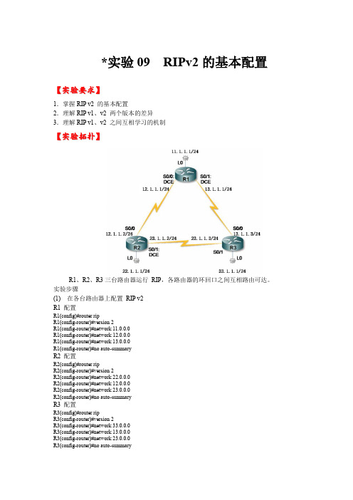
*实验09 RIPv2的基本配置【实验要求】1.掌握RIP v2 的基本配置2.理解RIP v1、v2 两个版本的差异3.理解RIP v1、v2 之间互相学习的机制【实验拓扑】R1、R2、R3三台路由器运行RIP,各路由器的环回口之间互相路由可达。
实验步骤(1) 在各台路由器上配置RIP v2R1 配置R1(config)#router ripR1(config-router)#version 2R1(config-router)#network 11.0.0.0R1(config-router)#network 12.0.0.0R1(config-router)#network 13.0.0.0R1(config-router)#no auto-summaryR2 配置R2(config)#router ripR2(config-router)#version 2R2(config-router)#network 22.0.0.0R2(config-router)#network 12.0.0.0R2(config-router)#network 23.0.0.0R2(config-router)#no auto-summaryR3 配置R3(config)#router ripR3(config-router)#version 2R3(config-router)#network 33.0.0.0R3(config-router)#network 13.0.0.0R3(config-router)#network 23.0.0.0R3(config-router)#no auto-summary(2) 在各台路由器上分别查看路由表 R1#show ip route rip33.0.0.0/24 is subnetted, 1 subnetsR 33.1.1.0 [120/1] via 13.1.1.3, 00:00:26, Serial0/123.0.0.0/24 is subnetted, 1 subnets R 23.1.1.0 [120/1] via 13.1.1.3, 00:00:26, Serial0/1[120/1] via 12.1.1.2, 00:00:10, Serial0/022.0.0.0/24 is subnetted, 1 subnetsR 22.1.1.0 [120/1] via 12.1.1.2, 00:00:10, Serial0/0R2#show ip route rip33.0.0.0/24 is subnetted, 1 subnetsR 33.1.1.0 [120/1] via 23.1.1.3, 00:00:06, Serial0/111.0.0.0/24 is subnetted, 1 subnetsR 11.1.1.0 [120/1] via 12.1.1.1, 00:00:14, Serial0/0 13.0.0.0/24 is subnetted, 1 subnetsR 13.1.1.0 [120/1] via 23.1.1.3, 00:00:06, Serial0/1 [120/1] via 12.1.1.1, 00:00:14, Serial0/0R3#show ip route rip22.0.0.0/24 is subnetted, 1 subnetsR 22.1.1.0 [120/1] via 23.1.1.2, 00:00:05, Serial0/1 11.0.0.0/24 is subnetted, 1 subnetsR 11.1.1.0 [120/1] via 13.1.1.1, 00:00:08, Serial0/0 12.0.0.0/24 is subnetted, 1 subnetsR 12.1.1.0 [120/1] via 23.1.1.2, 00:00:05, Serial0/1 [120/1] via 13.1.1.1, 00:00:08, Serial0/0(3) 把R3 的RIP 改为 v1 版本,R1、R2 保持v2 版本R3(config)#router ripR3(config-router)#no version 2 //残留的no auto-summary 不生效分别在 R1、R2、R3 上查看路由表 R1#show ip route rip23.0.0.0/24 is subnetted, 1 subnetsR 23.1.1.0 [120/1] via 12.1.1.2, 00:00:23, Serial0/0 22.0.0.0/24 is subnetted, 1 subnetsR 22.1.1.0 [120/1] via 12.1.1.2, 00:00:23, Serial0/0 R2#show ip route rip11.0.0.0/24 is subnetted, 1 subnetsR 11.1.1.0 [120/1] via 12.1.1.1, 00:00:23, Serial0/0 13.0.0.0/24 is subnetted, 1 subnetsR 13.1.1.0 [120/1] via 12.1.1.1, 00:00:23, Serial0/0R3#show ip route rip22.0.0.0/24 is subnetted, 1 subnetsR 22.1.1.0 [120/1] via 23.1.1.2, 00:00:14, Serial0/1 11.0.0.0/24 is subnetted, 1 subnetsR 11.1.1.0 [120/1] via 13.1.1.1, 00:00:11, Serial0/0 12.0.0.0/24 is subnetted, 1 subnetsR 12.1.1.0 [120/1] via 23.1.1.2, 00:00:14, Serial0/1 [120/1] via 13.1.1.1, 00:00:11, Serial0/0R2#debug ip rip events*Mar 1 01:28:44.419: RIP: ignored v1 packet from 23.1.1.3 (illegal version) //视为非法更新 *Mar 1 01:28:44.851: RIP: sending v2 update to 224.0.0.9 via Serial0/1 (23.1.1.2)(4) 使R1、R2的RIP v2 能学习R3 的RIP v1 路由更新 配置R2,不要配置R1R2(config)#int S0/1R2(config-if)#ip rip receive version 1 2 //使运行RIP v2的 R2能接收 v1、v2的 RIP 更新在各台路由器上查看路由表R1#show ip route ripR 33.0.0.0/8 [120/2] via 12.1.1.2, 00:00:09, Serial0/023.0.0.0/24 is subnetted, 1 subnetsR 23.1.1.0 [120/1] via 12.1.1.2, 00:00:13, Serial0/022.0.0.0/24 is subnetted, 1 subnetsR 22.1.1.0 [120/1] via 12.1.1.2, 00:00:13, Serial0/011.0.0.0/8 is variably subnetted, 2 subnets, 2 masks R13.0.0.0/8 is variably subnetted, 2 subnets, 2 masksRR2#show ip route ripR 33.0.0.0/8 [120/1] via 23.1.1.3, 00:00:27, Serial0/111.0.0.0/8 is variably subnetted, 2 subnets, 2 masksR 11.1.1.0/24 [120/1] via 12.1.1.1, 00:00:07, Serial0/0 R 11.0.0.0/8 [120/2] via 23.1.1.3, 00:00:27, Serial0/113.0.0.0/8 is variably subnetted, 2 subnets, 2 masksR 13.1.1.0/24 [120/1] via 12.1.1.1, 00:00:07, Serial0/0 R 13.0.0.0/8 [120/1] via 23.1.1.3, 00:00:27, Serial0/1 R3#show ip route rip33.0.0.0/8 is variably subnetted, 2 subnets, 2 masksR 33.0.0.0/8 [120/3] via 13.1.1.1, 00:00:03, Serial0/022.0.0.0/24 is subnetted, 1 subnetsR 22.1.1.0 [120/1] via 23.1.1.2, 00:00:04, Serial0/111.0.0.0/8 is variably subnetted, 2 subnets, 2 masksR 11.1.1.0/24 [120/1] via 13.1.1.1, 00:00:03, Serial0/0 R 11.0.0.0/8 [120/4] via 13.1.1.1, 00:00:03, Serial0/012.0.0.0/24 is subnetted, 1 subnetsR 12.1.1.0 [120/1] via 23.1.1.2, 00:00:04, Serial0/1[120/1] via 13.1.1.1, 00:00:03, Serial0/013.0.0.0/8 is variably subnetted, 2 subnets, 2 masksR 13.0.0.0/8 [120/3] via 13.1.1.1, 00:00:03, Serial0/0。
RIPv2协议配置

实验五RIPv2协议配置一、实验目的通过本实验,可以掌握以下技能:●配置接口IP地址。
●配置RIPv2协议。
●验证RIPv2协议配置。
二、设备需求●Cisco路由器3台,分别命名为twins、sa和gill。
其中twins具有2个以太网接口;sa具有2个以太网接口;gill具有2个以太网接口。
●2条交叉线序双绞线。
●1台access server,及用于反向Telnet的相应电缆。
●1台带有超级终端程序的PC机,以及Console电缆及转接器。
三、拓扑结构及配置说明实验的拓扑结构如图实验4所示,地址如下。
通过2对交叉线序双绞线分别把twins和sa连接起来、twins和gill连接起来。
各路由器使用的接口及其编号见图的标注。
各接口IP地址分配如下:●twins:E0:192.168.10.1 E1:192.168.11.1●sa:E0:192.168.10.2 E1:192.168.12.1●gill:E0:192.168.11.2 E1:192.168.15.1四、实验配置1.基本网络配置路由A:Router>enableRouter#config tRouter(config)#inetrface fastethernet 0/0RouterA(config-if)#ip address 192.168.10.1 255.255.255.0RouterA(config-if)#no shutdownRouter(config)#inetrface fastethernet 0/0RouterA(config-if)#ip address 192.168.12.1 255.255.255.0RouterA(config-if)#no shutdown同理,可配置路由B,路由C2.配置RIP协议路由A:Router(config)#router ripRouter(config-router)#version 2RouterA(config-router)#network 192.168.10.1 RouterA(config-router)#network 192.168.12.1 同理,可配置路由B,路由C五、验证RIPv2协议配置:1.show ip protocols2.show ip route该命令显示路由器的IP路由选择表,详细指出了路由器是如何获悉网络和发现路由。
- 1、下载文档前请自行甄别文档内容的完整性,平台不提供额外的编辑、内容补充、找答案等附加服务。
- 2、"仅部分预览"的文档,不可在线预览部分如存在完整性等问题,可反馈申请退款(可完整预览的文档不适用该条件!)。
- 3、如文档侵犯您的权益,请联系客服反馈,我们会尽快为您处理(人工客服工作时间:9:00-18:30)。
RIPv2配置实例1.用户需求:某企业总部计划和它的2个分公司联网。
计划采用2条数字链路连接总部和分公司,并要求总部和分公司的IP网络段不能相同,并且划分广播域隔离广播;不采用三层交换设备;两个分公司联网后能够互相访问;总部和分公司联网后路由器能够自动学习。
2.方案分析与解决:不采用三层交换技术,但要求采用数字链路,可以考虑用路由器。
3.网络拓扑:4.规划网络地址:PC1:192.168.3.2 255.255.255.0 192.168.3.1PC2:192.168.3.3 255.255.255.0 192.168.3.1PC3:192.168.4.2 255.255.255.0 192.168.4.1PC4:192.168.5.2 255.255.255.0 192.168.5.1总部路由器A:F0/0:192.168.3.1 255.255.255.0S1/0:192.168.1.1 255.255.255.0S1/1:192.168.2.1 255.255.255.0分公司路由器B:F0/0:192.168.4.1 255.255.255.0S1/0:192.168.1.2 255.255.255.0分公司路由器C:F0/0:192.168.5.1 255.255.255.0S1/1:192.168.2.2 255.255.255.05.路由器配置:总部A:Router>enRouter#conf tEnter configuration commands, one per line. End with CNTL/Z.Router(config)#hostname routerArouterA(config)#int f0/0routerA(config-if)#ip add 192.168.3.1 255.255.255.0routerA(config-if)#no shutdown%LINK-5-CHANGED: Interface FastEthernet0/0, changed state to up%LINEPROTO-5-UPDOWN: Line protocol on Interface FastEthernet0/0, changed state to uprouterA(config-if)#int s1/0routerA(config-if)#ip add 192.168.1.1 255.255.255.0routerA(config-if)#clock rate 64000routerA(config-if)#no shutdown%LINK-5-CHANGED: Interface Serial1/0, changed state to downrouterA(config-if)#int s1/1routerA(config-if)#ip add 192.168.2.1 255.255.255.0routerA(config-if)#clock rate 64000routerA(config-if)#no shutdown%LINK-5-CHANGED: Interface Serial1/1, changed state to downrouterA(config-if)#exitrouterA(config)#router riprouterA(config-router)#version 2routerA(config-router)#network 192.168.3.0routerA(config-router)#network 192.168.1.0routerA(config-router)#network 192.168.2.0routerA(config-router)#endrouterA#%SYS-5-CONFIG_I: Configured from console by consolerouterA#wrBuilding configuration...[OK]routerA#routerA#show ip routeCodes: C - connected, S - static, I - IGRP, R - RIP, M - mobile, B - BGPD - EIGRP, EX - EIGRP external, O - OSPF, IA - OSPF inter areaN1 - OSPF NSSA external type 1, N2 - OSPF NSSA external type 2E1 - OSPF external type 1, E2 - OSPF external type 2, E - EGPi - IS-IS, L1 - IS-IS level-1, L2 - IS-IS level-2, ia - IS-IS inter area* - candidate default, U - per-user static route, o - ODRP - periodic downloaded static routeGateway of last resort is not setC 192.168.1.0/24 is directly connected, Serial1/0C 192.168.2.0/24 is directly connected, Serial1/1C 192.168.3.0/24 is directly connected, FastEthernet0/0R 192.168.4.0/24 [120/1] via 192.168.1.2, 00:00:00, Serial1/0R 192.168.5.0/24 [120/1] via 192.168.2.2, 00:00:10, Serial1/1routerA#分公司B:Router>enRouter#conf tEnter configuration commands, one per line. End with CNTL/Z.Router(config)#hostname routerBrouterB(config)#int f0/0routerB(config-if)#ip add 192.168.4.1 255.255.255.0routerB(config-if)#no shutdown%LINK-5-CHANGED: Interface FastEthernet0/0, changed state to up%LINEPROTO-5-UPDOWN: Line protocol on Interface FastEthernet0/0, changed state to uprouterB(config-if)#int s1/0routerB(config-if)#ip add 192.168.1.2 255.255.255.0routerB(config-if)#clock rate 64000routerB(config-if)#no shutdown%LINK-5-CHANGED: Interface Serial1/0, changed state to uprouterB(config-if)#exit%LINEPROTO-5-UPDOWN: Line protocol on Interface Serial1/0, changed state to up routerB(config)#router riprouterB(config-router)#version 2routerB(config-router)#network 192.168.4.0routerB(config-router)#network 192.168.1.0routerB(config-router)#endrouterB#%SYS-5-CONFIG_I: Configured from console by consolerouterB#wrBuilding configuration...[OK]routerB#routerB#show ip routeCodes: C - connected, S - static, I - IGRP, R - RIP, M - mobile, B - BGPD - EIGRP, EX - EIGRP external, O - OSPF, IA - OSPF inter areaN1 - OSPF NSSA external type 1, N2 - OSPF NSSA external type 2E1 - OSPF external type 1, E2 - OSPF external type 2, E - EGPi - IS-IS, L1 - IS-IS level-1, L2 - IS-IS level-2, ia - IS-IS inter area* - candidate default, U - per-user static route, o - ODRP - periodic downloaded static routeGateway of last resort is not setC 192.168.1.0/24 is directly connected, Serial1/0R 192.168.2.0/24 [120/1] via 192.168.1.1, 00:00:18, Serial1/0R 192.168.3.0/24 [120/1] via 192.168.1.1, 00:00:18, Serial1/0C 192.168.4.0/24 is directly connected, FastEthernet0/0R 192.168.5.0/24 [120/2] via 192.168.1.1, 00:00:18, Serial1/0routerB#分公司C:Router>enRouter#conf tEnter configuration commands, one per line. End with CNTL/Z.Router(config)#hostname routerCrouterC(config)#int f0/0routerC(config-if)#ip add 192.168.5.1 255.255.255.0routerC(config-if)#no shutdown%LINK-5-CHANGED: Interface FastEthernet0/0, changed state to up%LINEPROTO-5-UPDOWN: Line protocol on Interface FastEthernet0/0, changed state to uprouterC(config-if)#int s1/1routerC(config-if)#ip add 192.168.2.2 255.255.255.0routerC(config-if)#clock rate 64000routerC(config-if)#no shutdown%LINK-5-CHANGED: Interface Serial1/1, changed state to uprouterC(config-if)#exitrouterC(config)#router riprouterC(config-router)#version 2routerC(config-router)#network 192.168.5.0routerC(config-router)#network 192.168.2.0routerC(config-router)#endrouterC#%SYS-5-CONFIG_I: Configured from console by consolerouterC#wrBuilding configuration...[OK]routerC#routerC#show ip routeCodes: C - connected, S - static, I - IGRP, R - RIP, M - mobile, B - BGPD - EIGRP, EX - EIGRP external, O - OSPF, IA - OSPF inter areaN1 - OSPF NSSA external type 1, N2 - OSPF NSSA external type 2E1 - OSPF external type 1, E2 - OSPF external type 2, E - EGPi - IS-IS, L1 - IS-IS level-1, L2 - IS-IS level-2, ia - IS-IS inter area* - candidate default, U - per-user static route, o - ODRP - periodic downloaded static routeGateway of last resort is not setR 192.168.1.0/24 [120/1] via 192.168.2.1, 00:00:17, Serial1/1C 192.168.2.0/24 is directly connected, Serial1/1R 192.168.3.0/24 [120/1] via 192.168.2.1, 00:00:17, Serial1/1R 192.168.4.0/24 [120/2] via 192.168.2.1, 00:00:17, Serial1/1C 192.168.5.0/24 is directly connected, FastEthernet0/0routerC#6.拓展知识:如果用PC终端连接到路由器上,要连路由器的Console口,连PC的RS 232接口。