宏碁MS2347拆机攻略
宏基上网本拆机图解
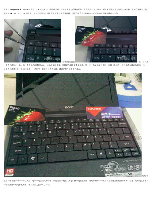
新买的Kingston DDR3 1333 -2G内存,150块钱买的:开始动手啦,拆卸是从上方的键盘开始。
首先观察一下上网本,可以看到键盘上方有几个小卡销,整体位置偏右上边,分别在F4、F8、F12、Del键上方;左上方比较空,因此先从左上方下手开始撬。
用两个小启子互相配合一点点小心的将键盘撬起一个角:一开始只能撬起一点,此时用一个启子撬住左上角,另一个启子将离最近的F4上方的卡销往里推,使撬起的部分更多更松动;整个左上角撬起后马上用一张硬卡片垫住,使之保持在撬起的状态:此时一边用启子将其它几个卡销往里推,一边用另一张卡片往右边刮撬,最后把整个键盘上方撬起;此时键盘左右还各有一个卡口卡住键盘,这个不是活动式的卡销,只能用点力硬撬,撬起后整个键盘就松了,此时从屏幕方向就能将整个键盘轻轻抽拿出来;注意,此时键盘下方有一个数据排线还连在机器上,千万别用力拉弄坏了排线。
这是键盘底下连着机器的排线:下一步是拆下排线(如果怕麻烦可以不拆这个排线,不过后面的步骤就需要时时非常小心以避免损坏排线)。
注意图片中卡住排线的那个插座,上方黑色部分是焊在机器的电路板上的,下面白色部分是连在上面的卡子,可活动的,往上推到顶可以把排线紧紧压在插座上,这是安装好的状态;用启子轻轻的将卡子左右的两个卡脚往下拨(见红箭头),这样白色的卡子就推下来了,排线就松了,轻轻的就拔了出来。
拔去排线后的插座,注意,白色的卡子已经推到了下方。
拆去键盘后的下面景象。
接下来用十字螺丝刀拆下四个标注“1”的螺丝;然后用螺丝刀对准标注为“2”的孔伸进去朝下推,稍微用点力,可以把上网本的底部整体盖板推下来;注意要先把整个上网本抱住左右两侧端起来,不要压住底盖,否则推不动的。
侧面看去,看到没,底盖一个角已经被推开了,顺势把整个底盖掰下来吧。
拆开底盖后的AspireOne522,内存条、硬盘一目了然;呵呵,此时想干啥就干啥吧。
换好内存后,机器拆下来的东西原样装回去就是,不再多叙述了;装键盘排线的时候要小心点,装好后别急着扣紧键盘,可先试试看好不好。
宏碁笔记本怎么拆机清理

宏碁笔记本怎么拆机清理
电脑使用久了就会堆积一些灰尘,影响使用。
下面就让店铺教大家宏碁笔记本怎么拆机清理吧。
宏碁笔记本拆机清理的方法
先翻过来背面,拆掉螺丝,取下电池。
揭开背面的盖子之后,拆掉内存条。
取掉螺丝,硬盘取得时候用力往左推。
取网卡的时候按住网卡的两个点就很容易的取下来了。
把背面的螺丝都卸下。
再把电脑翻过来,准备取键盘。
取得时候注意后面的排线。
一定要轻一些,用力过大容易导致连接的地方坏掉。
抠排线的时候,先把两头黑色的部分退出去,然后再取排线。
取出风扇的部分,卸下风扇就可以清理了。
按照步骤把电脑装回去,做开机测试。
宏碁TM_4730_4630系列计算机拆解教程

TravelMate 4730/4732Series Extensa 4630 SeriesDisassembly Instruction elMachine Disassembly and ReplacementThis chapter contains step-by-step procedures on how to disassemble the notebook computer formaintenance and troubleshooting.Disassembly RequirementsTo disassemble the computer, you need the following tools:•Wrist grounding strap and conductive mat for preventing electrostatic discharge•Flat screwdriver•Philips screwdriver•Plastic flat screwdriver•Plastic tweezersNOTE: The screws for the different components vary in size. During the disassembly process, group the screws with the corresponding components to avoid mismatch when putting back the components.General InformationPre-disassembly InstructionsBefore proceeding with the disassembly procedure, make sure that you do the following:1.Turn off the power to the system and all peripherals.2.Unplug the AC adapter and all power and signal cables from the system.3.Place the system on a flat, stable surface.4.Remove the battery pack.Disassembly ProcessThe disassembly process is divided into the following stages:•External module disassembly•Main unit disassembly•LCD module disassemblyThe flowcharts provided in the succeeding disassembly sections illustrate the entire disassembly sequence.Observe the order of the sequence to avoid damage to any of the hardware components. For example, if you want to remove the main board, you must first remove the keyboard, then disassemble the inside assembly frame in that order.External Module Disassembly ProcessExternal Modules Disassembly FlowchartThe flowchart below gives you a graphic representation on the entire disassembly sequence and instructs you on the components that need to be removed during servicing. For example, if you want to remove the main board, you must first remove the keyboard, then disassemble the inside assembly frame in that order.Removing the Battery Pack1.Turn computer over.2.Slide the battery lock/unlock latch to the unlock position.3.Slide and hold the battery release latch to the release position (1), then slide out the battery pack from the mainunit (2).12Removing the SD dummy card1.Push the SD dummy card all the way in to eject it.2.Pull it out from the slot.Removing the NewCard dummy card1.Push the NewCard eject button to eject it, then push it all the way in to eject the NewCard dummy.2.Pull it out from the slot.Removing the Lower Covers1.See “Removing the Battery Pack”2.See “Removing the SD dummy card”3.See “Removing the NewCard dummy card” .4.Loosen the five captive screws in the Memory, HDD, and WLAN bays as shown.5.Carefully open the memory cover.6.Remove the HDD cover as shown. HDD Cover Memory CoverWLANCover7.Remove the WLAN cover as shown.Removing the DIMM Modules1.See “Removing the Battery Pack” .2.Remove the Memory Module cover See “Removing the Lower Covers” .3.Push out the release latches on both sides of the DIMM socket to release the DIMM module.4.Remove the DIMM module.5.Repeat steps for the second DIMM module.Removing the WLAN Module1.See “Removing the Battery Pack” .2.Remove the WLAN cover. See “Removing the Lower Covers”3.Remove the adhesive tape and disconnect the antenna cables from the WLAN board.4.Move the antenna cables away and remove the two screws on the WLAN board to release the WLAN board.Step Size Quantity Screw Type WLAN Module M2*3 (NL)25.Detach the WLAN board from the WLAN socket.NOTE: When re-attaching the antenna to the WLAN board, make sure the cables are arranged under the WLAN bracket.Removing the Hard Disk Drive Module1.See “Removing the Battery Pack”.2.Remove the HDD cover, See “Removing the Lower Covers”e the mylar tab to slide and lift up the hard disk drive module to remove.NOTE: To prevent damage to device, avoid pressing down on it or placing heavy objects on top of it.4.Remove the HDD holder by easing the sides outward to clear the carrier.5.Remove the four screws securing the hard disk to the carrier.6.Remove the HDD from the carrier.StepSize QuantityScrew TypeHDD Carrier M3*3.5 (NL)4Removing the Optical Drive Module1.See “Removing the Battery Pack” .2.Remove the Memory cover. See “Removing the Lower Covers”3.Remove the screw securing the ODD module.ing a screw driver, push the ODD module through the chassis and pull to remove it from the main unit.StepSize QuantityScrew TypeODD Module M2.5*5(NL)15.Remove the three screws securing the ODD bracket and remove the ODD bracket from the ODD module.6.Insert a pin in the eject hole of the ODD to eject the ODD tray.7.Press down on the locking catch to release the ODD cover and remove.Step Size Quantity Screw Type ODD Bracket M2*3 (NL)3Main Unit Disassembly Process Main Unit Disassembly FlowchartRemoving the Switch CoverCAUTION: Using tools to remove the Switch Cover may cause damage to the outer casing. It isrecommended that only fingers are used to remove the Switch Cover.1.See “Removing the Battery Pack”2.Locate and remove the five securing screws as shown.3.Turn the computer over and open the LCD module fully to expose the Switch Cover.IMPORTANT:The LCD module must be fully open in the horizontal position to remove the switch cover.4.Lift the Switch Cover as shown, rightside first.5.Lift the Switch Cover clear of the chassis.StepSizeQuantity Screw Type Switch CoverM2.5*35Removing the Keyboard1.See “Removing the Battery Pack”2.See “Removing the Switch Cover”3.Remove the two screws securing the keyboard to the upper case.4.Lift the keyboard as shown to remove from the chassis.5.Turn the keyboard over and pull back the securing latch to release the FFC.StepSizeQuantity Screw TypeKeyboard M2*326.Remove the keyboard from the chassis.Removing the Power Board1.See “Removing the Battery Pack” .2.See “Removing the Keyboard” .3.Disconnect the Power Board cable from the mainboard.4.Remove the two securing screws from the Power Board.NOTE: The left hand securing screw is shared by the eKey Board.Removing the Launch Board1.See “Removing the Battery Pack” .2.See “Removing the Keyboard”3.Disconnect the Launch Board cable from the mainboard.4.Remove the two securing screws from the Launch Board.NOTE: The right hand securing screw is shared by the Power Board.StepSizeQuantityScrew TypePower BoardM2*32Removing the Antenna1.See “Removing the WLAN Module”2.Remove the Antenna Cables from the securing guides as shown.3.Turn the computer over, remove the adhesive tape and disconnect the FCC cables to expose the antennacables underneath.Step SizeQuantity Screw TypeLaunch BoardM2*324.Secure the FFC cable out of the way using the adhesive tape.5.Turn the computer over and push the cables through the underside of the chassis.6.Turn the computer over, and remove the cable from the mainboard as shown.7.Remove the Antenna Cables from the housing well as shown.NOTE: Place the cables to one side to avoid damage.Removing the LCD Module1.Remove the Battery Pack. See “Removing the Battery Pack”2.Remove the Lower Covers. See “Removing the Lower Covers”.3.Remove the WLAN Module. See “Removing the WLAN Module”4.Remove the Antenna. See “Removing the Antenna”5.Remove the two securing screws from the bottom of the chassis.6.Turn the computer over. Disconnect the LCD cable from the top panel.StepSizeQuantityScrew TypeLCD ModuleM2.5*8(NL)27.Remove the four securing screws (two on each side) connecting the LCD module.8.Carefully remove the LCD module from the chassis.StepSizeQuantity Screw TypeLCD Module (Red callout)M2.5*92LCD Module (Blue callout)M2.5*52Removing the Upper Cover1.See “Removing the Battery Pack” .2.See “Removing the LCD Module” .3.Turn the computer over. Remove the sixteen screws on the bottom panel.Step Size Quantity Screw Type Upper Cover M2.5x9164.Turn the computer over and disconnect the seven cables from the mainboard as shown.Disconnect A as shown. If necessary, remove FFC Gbefore beginning.Pull back the securing strip and disconnect B and C as shown.Remove the antenna cables from the housing andpull back away from the upper cover.Release the securing latches and disconnect E asshown.BE FG ADCBC5.Remove the single screw on the top panel.Disconnect the Power Board FFC (E) first beforeremoving FFC D. Pull back the locking latches torelease D.Release the securing latches and disconnect F asshown.Release the securing latches and disconnect G as shown.Step Size Quantity Screw TypeUpper Cover M2.5*9 (NL)16.Grasp the top left corner first and pry the cover off.7.Continue moving from left to the right corner and pry it off the lower cover.8.Move to the bottom right corner and pry it up.9.The Upper Cover can now be removed from the lower base.Removing the Finger Print Reader1.See “Removing the Upper Cover”2.Remove the securing screw from the Finger Print Reader board, and ensure the FFC is free of the upper cover.Step Size Quantity Screw Type finger print reader M2.5*3 (NL)13.Remove the board bracket from the Upper Cover.IMPORTANT:Do not throw away the Bracket Pad. Remove and replace on new bracket.Bracket Pading your fingers, gently lift the Finger Print Reader board from the Upper Cover.5.Pull the Finger Print Reader FFC through the touchpad bracket taking care not to fray the cable.Removing the Touch Pad Bracket1.See “Removing the Upper Cover”2.Peel back the Finger Print Reader FFC to expose the Touch Pad connector.3.Disconnect the Touch Pad FFC from the Touch Pad board.4.Lift up the covering and remove the securing screw.Step Size Quantity Screw Type Touch Pad Bracket M2.5*3 (NL)25.Remove the Touch Pad bracket.IMPORTANT:The Touch Pad cannot be removed individually. To replace the Touch Pad, replace the entire Upper Cover.Removing the Left Speaker Module1.See “Removing the Upper Cover”2.Peel back the adhesive strip to expose the speaker cabling.3.Remove the two securing screws.4.Grasp both ends of the mylar cover and carefully pull back to expose the speaker cable.StepSizeQuantity Screw TypeLeft SpeakerModule M2.5*3 (NL)2Removing the Right Speaker Module1.See “Removing the Upper Cover”2.Remove the two securing screws from the speaker module.3.Grip the Speaker Module and remove.StepSizeQuantity Screw TypeRight SpeakerModule M2.5*3 (NL)22.Remove the adhesive strip to expose the Bluetooth cable.3.Disconnect the bluetooth cable as shown.4.Lift the corner of the module up, then grasp to remove.2.Disconnect the RJ-11 cable as shown.3.Remove the two (2) securing screws.4.Lift the module and remove from the lower cover as shown.StepSize QuantityScrew TypeModem Module M2*3 (NL)2Removing the Mainboard1.See “Removing the LCD Module” .2.See “Removing the Upper Cover” .3.See “Removing the Modem Module”4.Turn the lower base over on a clean surface, and disconnect the DC-IN cable as shown.IMPORTANT:Ensure the cable can easily pass through the lower cover during mainboard disassembly.5.Turn the base rightside up, and disconnect the bluetooth cable from the bottom right of the mainboard asshown.6.Remove the two securing screws from the Mainboard.7.Lift the mainboard to expose the DC-IN jack and USB cable.8.Remove the DC-IN jack and USB cable as shown.StepSize Quantity Screw TypeMainboard M2.5*9 (NL)Green Call out 1Mainboard M2.5*3 (NL)Red Call out 19.Grasp the mainboard by both sides and pivot upwards to remove.CAUTION: Ensure the I/O ports at the bottom of the mainboard are clear of the bottom base to prevent damage to the mainboard.1.Remove the mainboard. See “Removing the Mainboard” .2.Remove cable from the USB board.3.Remove the two securing screws from the USB board and lift clear of the chassis.1.See “Removing the Mainboard”2.Disconnect the RJ-11 cable from the modem module.3.Grasp the cable and gently lift it out of the housing well.4.If necessary insert tweezers in the RJ-11 jack, lift the RJ-11 jack from the base.Removing the Thermal Module1.See “Removing the Battery Pack” .2.See “Removing the LCD Module”3.See “Removing the Upper Cover”4.See “Removing the Mainboard”5.6.Disconnect the fan module cable from mainboard.Step Size Quantity Screw Type CPU ThermalModule(red call out)M2*6.54VGA ThermalModule(blue call out)M2*347.Lift the Thermal Module clear of the Mainboard.Removing the CPU1.See “Removing the Battery Pack”2.See “Removing the Upper Cover” .3.See “Removing the Mainboard” .4.See “Removing the Thermal Module”.ing a flat screwdriver, turn the CPU socket latch counter-clockwise 180° to release the CPU.6.Lift the CPU clear of the Mainboard.Removing the VGA Module1.Remove the mainboard. See “Removing the Mainboard” .2.Remove the two securing screws from the VGA Module.3.The VGA module lifts automatically from the mainboard. Remove the VGA Module as shown.StepSizeQuantity Screw TypeVGA Module M2*4-NI (NL)2LCD Module Disassembly Process LCD Module Disassembly FlowchartRemoving the LCD Bezel1.Remove the LCD module. See “Removing the LCD Module” .2.Remove the two upper and two lower bezel screw caps. Remove the four securing screws from the LCDmodule.3.Lift up the bezel, topside first, and remove it from the LCD Module.Step SizeQuantity Screw TypeLCD Bezel M2.5*5 (NL)42.Remove the securing tapes from the left and right sides of the Inverter board as shown.3. Remove the two securing screws from the Inverter board and lift the board clear of the LCD Module.4.Remove the Inverter Board from the LCD Module.StepSize Quantity Screw TypeInverter Board M2.5*6 (NL)22.Disconnect the Camera Module cable as shown.3.Remove the two securing screws from the Camera Module bracket.Step Size Quantity Screw Type Camera ModuleM2*3 (NL)2。
acer拆机重点步骤

这款本儿的三种螺丝,左起从小到大。
红色圈内的是最大的那种螺丝,黄色三角的是中号。
很容易区分,下文在再不做特殊标记。
后盖容易去下,拧松螺丝后,在凹陷处一撬即可开启。
拧掉图示中的螺丝。
把无线网卡上的白色排线拔掉。
硬盘,照图示箭头插入起子一类的即可轻松撬开。
最难拆的是键盘部分,留意F4,F8,F12处的活动卡扣。
找东西将卡扣顶进去,任意两个卡扣顶进去后,键盘就会微微翘起。
三个卡扣处理好后,就如下图所示↓↓↓↓↓注意,在键盘左右两侧,各有两个不活动的卡扣(Esc,Tab;Del,Pg up键位旁)。
此时需要稍微用点力气将键盘“取”下来,只要多注意,用巧劲,不是很难。
键盘脱离上述卡扣束缚后,照图示使键盘微微水平向前,使底端4个嵌入式卡扣脱离。
慢慢抬起,可以看见键盘排线,此处小心,据说很多人第一次都拉断了。
如图示方向,向上拉起黑色“保险”。
那个黑色卡条具体学名也不太清楚,鄙人就叫它"保险“了,见笑。
红色标识的螺丝拧下,黄色标识的排线取下。
排线取法:将两边的黑色保险照图示箭头方向拉下。
抓住塑料片,按照图示方向即可轻松取下。
方法同上,黑色保险朝上拉。
用针一类的东西,如图插入,打开光驱。
此处有两颗螺丝,位置很隐蔽,一一取下。
现在就可以开始取c面了。
从右侧光驱位置开始,按顺时针,循序渐进,用起子慢慢撬至左侧,切不可操之过急!这一步很重要,也是本机第二难拆的部位。
用力一定要适度,否则内侧卡扣很容易被撬断,切记~~~切记~~~~c面取下。
黄色圆圈处的螺丝取下,红色方框处的排线取下。
光驱照图示方向从左端轻推即可取出。
主板已无束缚,从右侧轻拉,即可取下。
主板正面,风扇上的4个螺丝就是本机最小规格的。
时间:2012-03-10 14:28:07 快门:1/29 光圈:F/2.8 焦距:4毫米感光度:114涂硅脂一定要尽量少而均匀(网上说的“薄如蝉翼”),切不可一味求多,那样只会适得其反,切记~~CPU,芯片表面涂薄薄一层即可,一定要均匀,GPU也一样。
ThinkPad 系列笔记本拆机教程
最近天气变暖,颇有点夏天的味道了。
上午玩了会游戏,网页版的,cpu直接冲到50+,显卡更是飙到小70.说到这里,我就知道有问题了。
我的小e,是a64版本的,买的时候是10年的11月份,貌似说已经过保。
当时由于我的cq41-204tx刚刚摔了,所以买的这个机器。
直到现在从未有过清灰的经历。
正好昨天店里面没有什么事情(个人是做正骨的,所以什么棉签,什么酒精都是现成的),下午出去买了点硅脂,袋装的,上面写着超频三,神马pccooler的东西,两元一包,买了两包,用了一个,里面是白色的硅脂,个人感觉有点稀,但是在这种地方买不到什么好的(青岛西元庄,有需要的同学可以来找我,免费给你们清灰哦...)。
又花了两块五买了一个毛刷,一个小盒的缝纫机油。
回来后,开始拆机!以前机器加过内存,所以后盖那块很容易就拆下来了,螺丝+卡口的组合,从上面直接拿掉。
高潮来了...打开了cpu上的四个螺丝,显卡上面的两个,以为应该可以拿掉散热器模块的,可是实际上是各种难拿,由于纯铜做的导热,不敢硬来,变形了之后cpu和显卡的贴合会不是那么好。
到这里索性一不做,二不休,全拆了!上图!器材:三星B5510(GALAXY Y PRO)[三星手机]时间:2012-04-08 快门:1/14 光圈:F/2.6 焦距:2毫米感光度:125器材:三星B5510(GALAXY Y PRO)[三星手机]时间:2012-04-08 快门:1/19 光圈:F/2.6 焦距:2毫米感光度:125器材:三星B5510(GALAXY Y PRO)[三星手机]时间:2012-04-08 快门:1/11 光圈:F/2.6 焦距:2毫米感光度:160器材:三星B5510(GALAXY Y PRO)[三星手机]时间:2012-04-08 快门:1/13 光圈:F/2.6 焦距:2毫米感光度:125器材:三星B5510(GALAXY Y PRO)[三星手机]时间:2012-04-08 快门:1/17 光圈:F/2.6 焦距:2毫米感光度:125器材:三星B5510(GALAXY Y PRO)[三星手机]时间:2012-04-08 快门:1/30 光圈:F/2.6 焦距:2毫米感光度:80器材:三星B5510(GALAXY Y PRO)[三星手机]时间:2012-04-08 快门:1/18 光圈:F/2.6 焦距:2毫米感光度:125器材:三星B5510(GALAXY Y PRO)[三星手机]时间:2012-04-08 快门:1/30 光圈:F/2.6 焦距:2毫米感光度:100器材:三星B5510(GALAXY Y PRO)[三星手机]时间:2012-04-08 快门:1/15 光圈:F/2.6 焦距:2毫米感光度:125器材:三星B5510(GALAXY Y PRO)[三星手机]时间:2012-04-08 快门:1/11 光圈:F/2.6 焦距:2毫米感光度:125器材:三星B5510(GALAXY Y PRO)[三星手机]时间:2012-04-08 快门:1/21 光圈:F/2.6 焦距:2毫米感光度:125器材:三星B5510(GALAXY Y PRO)[三星手机]时间:2012-04-08 快门:1/11 光圈:F/2.6 焦距:2毫米感光度:125器材:三星B5510(GALAXY Y PRO)[三星手机]时间:2012-04-08 快门:1/30 光圈:F/2.6 焦距:2毫米感光度:100手机拍的,不是很清楚,莫怪。
笔记本屏幕拆机教程-acer
ACER-5520笔记本拆解之-屏幕篇时间:2010-11-0314:26来源:艾瑞笔记本拆解网作者:chaichai点击:680次前几天我们拆解了这款5520笔记本的主机(/thread-4343-1-1.html),今天我们有空继续将这台NB的液晶屏幕拆解并出一个小的教程,供大家学习参考!宏基系列笔记本主机比较难拆,但是屏幕都是公认非常好拆的,不论什么系列的笔记前几天我们拆解了这款5520笔记本的主机(/thread-4343-1-1.html),今天我们有空继续将这台NB 的液晶屏幕拆解并出一个小的教程,供大家学习参考!宏基系列笔记本主机比较难拆,但是屏幕都是公认非常好拆的,不论什么系列的笔记本,ACER基本上都是是这样的屏框设计。
下面就是详细的屏幕拆机过程图片:按照艾瑞拆解网的习惯我们还是拆机前来张整机ACER5520的照片我们将笔记本电脑关闭,然后看到下面红圈标注的位置,就是屏幕外壳固定的4个螺丝使用小刀或者其他工具将保护的橡胶垫取出来,一共四个都需要弄出来我们从右边动手,如图中,右上角慢慢的取出屏幕框上面全部取出来后,继续将液晶屏幕下面的部分取出来注意最下面的这个位置,别弄断了这个转轴上面的塑料片这样我们就可以将宏基5520的屏幕框拆下来了这里中间位置是笔记本电脑的屏幕高压电路,是给屏幕以及灯管供电的,最左右段的螺丝是用来固定屏幕的以及屏幕最上方,有一个摄像头的数据线,我们按照箭头符号拔出线头慢慢的将屏幕放置到键盘上面,如下图中:屏幕背面有链接的屏线,一般上面有个小的塑料片粘在上面,取出来后,拔出排线如下面图片中,撕开胶带的时候特别小心点,别把线弄断了以及最下面有个屏幕的供电线路,按照箭头符号拔出来即可液晶屏幕的左右两端还有几个螺丝固定,如图中ACER5520的轴固定了几个螺丝还有左边的几个完成上面的工作后,你就能将ACER5520笔记本的屏幕取出来了这个是液晶屏幕的配件编号以上就是本次ACER5520笔记本的拆机更换屏幕的全部教程。
宏碁笔记本拆机教程

宏碁笔记本拆机教程
如果您想了解如何拆解宏碁笔记本,我们将为您提供一个简单的教程。
拆解笔记本可能会对硬件造成损坏,因此,请您在拆解之前确保备份所有重要数据,并在确保了解自己的操作能力后进行操作。
在拆解之前,您需要准备一些必要的工具,如螺丝刀、塑料刮板和细小的夹子。
第一步是关闭电脑并断开电源连接。
确保您已经关闭了电源并拔掉电源适配器。
同时,还需要将电池拆卸掉,以避免电流对您造成伤害。
第二步是使用细小的螺丝刀在笔记本的底部找到所有的螺丝。
这些螺丝通常带有一个小图标,用以表示该螺丝应该拧松。
使用螺丝刀拧松它们并将它们放在一个安全的地方,以防丢失。
第三步是使用塑料刮板或相似的工具来慢慢弯曲和拆卸笔记本的外壳。
通常情况下,外壳被固定在一起,需要小心地将其揭开。
利用塑料刮板贴近外壳,然后轻轻地用力将其撬开。
需要注意的是,在撬开过程中要避免使用过大的力量,以免导致外壳、电路板或其他硬件的损坏。
第四步是拆卸内部硬件。
首先,在拆卸之前要先熟悉笔记本的内部结构和硬件组件的位置。
通常来说,硬盘、内存、无线网卡和风扇都是常见的内部硬件组件。
运用夹子轻轻地拆下这些硬件,确保不要损坏金属接头或电缆。
最后,将拆解的过程倒过来,重新组装笔记本。
确保将每个硬
件部件正确地插入到相应的插槽或接口中,然后将外壳盖好并用螺丝刀拧紧螺丝。
总结:拆解宏碁笔记本需要小心和耐心,确保在拆卸和组装过程中不损坏硬件。
如果您对自己的操作能力不确定,强烈建议联系专业技术人员来进行拆解和维修。
宏基ACERV3-772G拆机图.
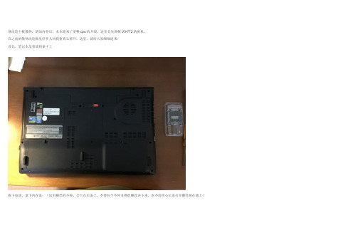
继改造主板散热,增加内存后,本本迎来了更换cpu的升级。
这里首先讲解V3-772的拆机。
在之前的散热改造贴里好多人问我要真么拆开,这里,就给大家细细道来:首先,笔记本反着放到桌子上拆下电池,拿下内存盖:(这里螺丝拆不掉,会卡在后盖上,不要拧个不停非得把螺丝弄下来,也不用担心后盖打开螺丝掉在地上)打开后,我们就看到了内部,接下来,取下 1内存 2硬盘 3光驱 4网卡 5电源线:取网卡记得先拔下天线,记得拔下电源线:然后拧下外壳螺丝,这里所有螺丝必须拧下来,保管好,这些螺丝不会卡在外壳上,反过来就都掉下来了哦~~全部拧完了后,反过来电脑,正常姿势打开我一般从右下动手慢慢抬起,如果觉得力量挺大,有明显弯曲说明有螺丝没有松开,正常的有点儿力气这里就开了,然后挑开排线开关:像这样,不要直接拔,先把黑片挑起来:然后拿下前盖,这里只有右边一个螺丝要拆:然后慢慢从右边抬起键盘,左边有卡扣,注意稍微向右拉点儿,不要太猛直接拽下来,你就可以买新键盘了:然后不要直接掀开,要从后面掀起来,如图:然后排线在另一侧,站起来从上面卸掉:键盘就拿下来了:(键盘背面爆照)接下来开始拆主板,螺丝有4个(貌似是,大排线没有拆记得拆),拔下来显示器线,如箭头所示直接提着塑料绳抬起来就好:这里注意的是,主板因为螺丝孔很多,只有少部分是固定主板的螺丝,都会用三角标出,例如:大家装的时候记得只上这些带三角的螺丝,不然外壳螺丝有可能就没有地方拧了,然后导致全部返工。
然后慢慢从右端抬起主板:抬起直到接近75度(这里如果电源线和WIFI天线没有拔,会被扥住,所以务必记得拔下来)。
这里差不多这个角度就可以顺利拿下来主板了:来一张全家福,主板上还可以看到我上次改造的南桥散热片~~~~~:然后开始拆开散热,根据个人需求,换散热硅脂,清理风扇等:更换CPU:拆下散热后看到GPU:和CPU。
这里用六角螺丝刀T-8,拧开这里的锁扣:取下CPU(小心翼翼),新老CPU对比:这里我们简单介绍下,v3 772采用的是i7 4702MQ,是这里最低的处理器,直接上最高的散热怕有问题,那么同等47w的情况下,要最高的,恩,所以我换的是4900MQ(这里只能换47W的,因为没有37W的了)。
- 1、下载文档前请自行甄别文档内容的完整性,平台不提供额外的编辑、内容补充、找答案等附加服务。
- 2、"仅部分预览"的文档,不可在线预览部分如存在完整性等问题,可反馈申请退款(可完整预览的文档不适用该条件!)。
- 3、如文档侵犯您的权益,请联系客服反馈,我们会尽快为您处理(人工客服工作时间:9:00-18:30)。
宏碁拆机清灰攻略
小编是动手一族,自从从前段时间对照着百度图文攻略拆掉自己的LenovoV470的机子后就已发不可收拾,琢磨着自己也做一些其他机型的拆机图文攻略。
最近网购了一套拆机工具就一直在拆机,但都没有整理。
今天帮同事的宏碁MS2347重装了win7的系统后发现机子特别烫。
他说机子用了三年一直没拆过,所以就本着帮助他人成就自己的想法拆了机子,做了这个图文,希望对喜欢动手的朋友有帮助。
下面是拆机过程中拍的重要部位的特写:
机子A面(显示器背面)及logo
机子C面(电源键、键盘、触控板)
开工,首先拆掉固定光驱的一颗螺丝,抽出光驱
接下来拆掉硬盘后盖的三颗螺丝及电池
比较简单,硬盘后盖只有三颗螺丝,拆掉之后就可以把后盖抠下来就可以看到内部。
本机只有一个2G的内存条,不卡才怪。
果断先拿下内存条!
接下来是拆掉硬盘的一颗固定螺丝(表示对于硬盘只用一颗螺丝固定有些
担忧)。
拔掉无线网模块的黑白线插头,拆掉螺丝无线网模块就会自动弹起来。
将拆下来的电池、硬盘、内存条、无线网卡先放到一边。
接下来拆掉D面能见到的所有螺丝,忘记拍照片了,也比较简单所以这里就不啰嗦了。
拆完所有螺丝接下来就是拆键盘啦,键盘上有5个卡扣,用镊子
逐个拨开,就可以把键盘抠起来。
要注意的是键盘下面有排线,千万不要太大力把排线弄坏了。
把排线接头的黑色压条抠起来,抽出排线就OK啦。
把键盘先放到一边,可以看到排线下面有一颗螺丝,果断拆掉它。
先别着急,还有两个排线要拔掉,他们就是触控板排线和电源键及音响排线。
拔掉排线就可以拿下C面面板了。
我们看看面板里面长什么样。
拿掉C面面板后就可以看到内脏了,主板。
华硕的机子大都采用这种大板+小板布局,中间用排线连接的方式。
拆掉固定主板的最后一颗螺丝,拔下显示器排线
为了给硬盘留出空间,另外做了一个麦克风,耳机、及一个USB外接模块,用排线连接到主板上。
拔掉这个小模块于主板的链接排线。
拔除了能看到的所有排线,拆掉了最后一颗螺丝就可以拿下主板了,让我们仔仔细细看看主板。
再反过来看一下
拆掉上图中的7颗固定螺丝,拔下散热器的电源线就可以把整个散热系统拿下来。
看一下拿掉散热系统后的主板
拆掉风扇盖板上的三颗小螺丝。
让我们看一看风扇内部结构。
这是本次核心工作,让小编把他清理干净。
清理到这里就差不多了,后面就是擦掉CPU、GPU上干掉的的导热硅胶涂上新的导热硅胶,然后按照拆机的顺序逆向一步一步组装起来就OK了,这里就不细说了。
就拆机整体而言,难度不是很大,有几个需要注意的点:一是拆C面(键盘)面板时一定要先拆掉排线,二是装机时一定要记得插上风扇的电源线(小编就忘了)。
切记不要赶时间,一步一步来,尤其是新手。
希望帖子对广大动手一族有帮助。
编辑:志超。