TB-4同步控制器使用说明
[整理版]同步控制器使用说明书
![[整理版]同步控制器使用说明书](https://uimg.taocdn.com/e3633ee6f80f76c66137ee06eff9aef8941e489a.webp)
同步控制器使用说明书
一、产品特点:
◆ 按键控制光源的变化效果。
智能存储客户最后使用的信息。
◆ 控制器可控制10种效果。
可长时间实现同步控制效果。
◆ 同步控制中,调节默认主控可改变其他从控制器的效果。
二、产品图片:
三、按键及功能说明:
SW-SET 为功能速度键,短按SW-SET 键调节速度(在渐变、跳变过程中有效),长按SW-SET 键调节控制器的控制模式。
模式共有10种,分别为:红、黄、绿、青、蓝、紫、白、渐变、跳变、自动。
四、控制器参数表
五、单机接线图:
六、主从同步接线图:
七、注意事项:
1、通电之前,请测量使用工作电压是否正确。
2、请确定负载电流在控制器额定输出电流范围内。
八、常见故障排查:
1、如遇红灯未亮请确定输入电压是否正常。
2、开机后红灯亮但未见负载工作,请检查同步信号输入是否正确。
3、连机过程中,如遇不同步现象(主控制器调节后,分控制器有一周期的不同步现象),请检查从主控制器与下一级分控制器之间的同步线(注:两机之间同步线最大距离为20M ),如果正常请依次检查前者从控制器的输出与下一级从控制器的输入之间的同步线。
天津核奥达门机控制器操作说明
HAD-YCB型矢量控制永磁同步变频电梯门机控制器使用说明书天津市核奥达新技术开发有限公司目录重要提示!一.安全规程1.安全注意事项2. 使用注意事项二.产品介绍1.指标及规格1.1.环境1.2.结构1.3.输入、输出1.4.保护功能1.5.版本说明2.安装接线2.1.安装尺寸2.2.端子说明3.门机控制器接线图4.操作面板说明5.电源和自动手动开关6.参数表三.门机调试及注意事项1.注意事项1.1.F45、F46、F47、F56、F57、F58、F59、F60参数说明1.2.偏移量学习说明2.门机调试2.1.同步带调整说明2.2.对于门的滑动程度要求2.3.新购买门机调试说明2.4.参数如何修改2.5.如何学习偏移量2.6.如何确定同步门刀收刀位置2.7.如何完成门机自学习2.8.多段速曲线图及说明2.9.学习完成后如何进入正常模式重要提示:1.轿厢运行前给出关门指令!2.轿厢运行中必须始终给出关门指令3.开关门控制信号必须是无源触点!4.厅轿门联动,不管门处于何种位置,水平关门方向不大于150牛顿力作用于门扇时,门应能够正常关闭。
5.显示E01表示编码器未工作或者是门开不动或关不动。
6.矢量控制永磁同步变频门机使用4096磁电编码器。
7.对于同步门刀门机必须保证收刀后,再接通副门锁以确保电梯安全运行。
8.电机外壳、门机控制器外壳、AC220电源的地线,必须可靠接地一.安全规程1.安全注意事项1.1.不能安装在含有易燃、易爆性气体的环境里(除专用防爆变频器),否则引起爆炸的危险。
1.2.必须由具有专业资格的人员进行接线作业,否则有触电危险。
1.3.确认输入电源处完全断开的情况下,才可进行接线操作,否则有触电危险。
1.4.必须将变频器的接地端子可靠接地,否则有触电危险或者造成门机不能正常工作。
1.5.操作及安装时应注意不能有金属、水、油或其他异物,否则损坏变频器或造成变频器不能正常工作。
2.使用注意事项2.1.在布线过程中始终注意信号线及控制线(弱电)与强电(36V以上)之间必须保持一定距离,不可混在一起布线,否则造成不能正常工作。
环希工业 240说明书(1)
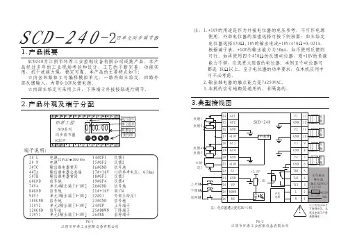
端子说明:
运行指示 单元指示 数据指示
操作按钮
1# L 2# N 3#TC 4#TA 5#TB 6#GND 7#V4 8#GND 9#V3 10#GND 11#V2 12#GND 13#V1
电电源源220VAC±20%50Hz 输出继电器常开 输出继电器公共端 输出继电器常闭 信号地 单元4输出端[0-10V] 信号地 单元3输出端[0-10V] 信号地 单元2输出端[0-10V] 信号地 单元1输出端[0-10V]
N 1 1A 250V 50Hz
注:电位器建议使用2K-10K
P6-2 江阴市环希工业控制设备有限公司
以上灰色区域为
! 可接强电区,本 机其他端子严禁
接触强电.
参数表
参数号 F01 F02 F03 F04 F05 F06 F07 F08 F09 F10 F11 F12 F13 F14 F15 F16 F17 F18 F19 F20 F21 F22 F23 F24 F25 F26 F27 F28 F29 F30 F31 F32 F33
14#GF1 15#GF2 16#GND 17#+10V 18#GF3 19#GF4 20#GND 21#+10V 22#G1 23#GND 24#UP 25#DOWN 26#RS
反馈1 反馈2 信号地 +10V参考电压,≤50mA 反馈3 反馈4 信号地 同17# 外部主给定1 信号地 上升端子 下降端子 启停端子
0:解锁 ቤተ መጻሕፍቲ ባይዱ:锁定 给定从0升到10V所需时间
范围0-100秒 范围0-13*
! 按ENT则参数恢复出厂值**
范围0.00-10.00
端子26闭合时:0:无动作1:G0=F22 0.01:最慢 4.00:最快
同步控制器使用手册
安全须知无论在任何情况下,如操作、清洁或保养,请务必遵守以下所规定的安全守则,若有因违反,而造成超出原设计、制造的安全顾虑,本公司将不予以负责。
当地若另有其它的安全规范,则请一起遵守。
警告:请在本设备允许的操作和储存环境条件下使用。
·任何情况下,无专业人员指导,切勿拆卸或碰触内部零部件;·维修设备时,严禁带电操作;·切勿使金属、液体等异物掉入设备内,以免设备损坏;·设备安装尽量远离干扰源(例如:接触器、变频器等)或采取相应的屏蔽措施;·信号线、电源线最好分开走线,以免产生干扰;·本设备与接触器不可共享一个电源,否则会有干扰产生;·本设备专门为本公司生产的VFD系列变频器配套使用而设计,使之能够发挥最佳性能,但不能保证与其它品牌变频器的匹配。
储存本品在安装之前必须置于其包装箱内,若该机暂不使用,为了使该品能够在本公司的保修范围内以及日后的维护,储存时务必注意下列事项:☞必须置于无尘垢、干燥之位置。
☞储存位置的环境温度必须在0℃到+65℃范围内。
☞储存位置的相对湿度必须在5%到90%范围内,且无结露。
☞避免储存于含有腐蚀性气、液体之环境中。
☞最好适当包装并存放在架子或台面上。
操作环境☞环境温度0℃-+50℃,若环境温度超过40℃以上时,请置于通风良好之场所。
☞相对湿度15%-+95%RH,避免安装与任何发生结露、冰冻或要接触任何液体之场所。
☞不要安装一任何有以下情况的场所:阳光直晒、浓灰尘、腐蚀性气体或油雾、易燃性气体、液体。
☞震动小于5.9米/妙(0.6g)。
SLC系列同步控制器拥有完善的功能,在技术上处于国内领先水平,在性能上可与国外同类产品相媲美。
广泛适用于由多台调速系统组成的各种机械设备上,如电力、钢铁、造纸、纺织、印染、电缆光纤、塑料等行业。
可对线速度、位移、张力、距离等进行控制,是机器设备的最佳选择。
一、型号说明SLC 04C22 (A)B 为反馈电压为0-10VA 为反馈电压为±5V控制器输出路数4路控制器系列号1、主要特点A、数字化SLC04C22A(B)控制器采用单片计算机控制,可对控制器进行多种参数设置,设置参数时通过数码显示。
超同步45P5GH1B说明书
GH DRIVERCTB资料编号:Z L-14-808-I B C NB E I J I N GC T B S E R V O C O.,L T D.GH DRIVER使用说明书交流伺服驱动器型号:BKSC-□□□□GHX400V级 1.5~315KW (2.5~460KVA)请将此使用说明书,交给最终用户,并妥善保存CTB TECHNOLOGY北京超同步伺服股份有限公司序 言感谢您惠购北京超同步伺服股份有限公司生产的GH系列交流伺服驱动器。
GH系列交流伺服驱动器是北京超同步伺服股份有限公司研制、开发生产的高品质、多功能、低噪音的交流伺服驱动器。
G H系列交流伺服驱动器是交流感应电机(I M)及交流永磁同步电机(PM)的交流伺服驱动器,可对各种交流伺服电机的位置、转速、加速度和输出转矩方便地进行控制,G H系列交流伺服驱动器采用双32位C P U,配置丰富的控制功能模块,可以实现各种机床的控制功能。
标配的控制接口可以和国内外各种数控系统方便地连接,使数控系统的功能得以充分地发挥。
配置G H系列交流伺服驱动器的机床,其力矩特性、加减速特性、精度特性以及效率特性都将表现非凡,并可以轻松地实现准停、C轴、刚性攻丝、电子换挡、多轴同步等功能。
G H系列交流伺服驱动器,可广泛应用于数控铣床、立式加工中心、卧式加工中心、数控镗床、数控车床、立车、重型卧车、龙门机床等产品的驱动,是各种机床动力轴的首选驱动产品。
在使用G H系列交流伺服驱动器之前,请您仔细阅读该手册,以保证正确使用。
错误使用可能造成驱动器运行不正常、发生故障或降低使用寿命,乃至发生人身伤害事故。
因此使用前应反复阅读本说明书,严格按说明使用。
本手册为随机发送的附件,务必请您使用后妥善保管,以备日后对驱动器进行检修和维护时使用。
01本说明书中与安全有关的内容,使用了下述符号,标注了安全符号的语句,所叙述的都是重要内容,请一定要遵守。
如果未按安全内容要求,使用该产品可能会造成产品使用不正常,甚至损坏产品,严重的可能会引起危险、造成人身伤亡。
Victron Energy Hub-4模式2和3操作指南说明书
Hub-4 mode 2 and 3This page explains how to use a Multi/Quattro as a bidirectional inverter operating parallel to the grid, integrated into a customer designed system (PLC or other). In mode 2, Advanced, or more 3, Custom.Note that it is also possible to run a Victron grid parallel storage system without designing and implementing your own control loop, logic or measurements. See the Hub-4 manual.Note that though this page mentions Hub-4, which is deprecated, it also applies to ESS.1. Overview of Hub-4 operating modes1.1 Mode 1 - StandardThe system runs automatically, and uses excess energy harvested during the day to fill the gaps when there is not enough PV power available. Typically in the evening and night. Easy configuration in Assistants and on the Color Control GX. For details refer to the main hub-4 manual.1.2 Mode 2 - AdvancedSame as standard operating mode, but customer adds custom control doing time shifting, load management or other energy management optimization algorithms. The required components in the system, as well as the general software setup, is 100% equal to the default, Mode 1. The available control points are:Grid power setpointMaximum charge percentageMaximum discharge percentageThere are two ways access those control points:Send commands to the CCGX via ModbusTCP, from an external control module, a PLC for 1.example.2.Run self-implemented scripts on the CCGX, same functionality, but then it is not needed to adda PLC to the system.For more information, see the Mode 2 details.1.3 Mode 3 - CustomCustomer self implements their control loop and grid measurements, and uses the MultiPlus and/or Quattros as simple, remote controllable, bidirectional inverter/chargers that can be set to either charge or discharge an x amount of Watts. Note that the point of control is the AC-input, not the charger itself.update:system_integration:hub4_grid_parallel_external_control_loop https:///live/system_integration:hub4_grid_parallel_external_control_loop 2019-01-2210:16Power to/from AC-input = Power to/from battery + Power to/from AC-output Necessary Victron equipment:1.Multi or Quattro inverter/charger2.Color Control GX3.Note that there is no AC sensor necessary, since the inverter/charger will act as a 'dumb' bi-directional inverter/charger. It will act on the external command given, which can for example be 'take 2000W from AC in, or feed back 100W through AC in'.Available control points:Switch (on, charger-only, inverter-only, off)Power setpoint in Watts: regulates the power on the ac-input.Disable charge flagDisable feedback flagFor more information, see the Mode 3 details.2. Details of operating mode 2 - Advanced2.1 Available control pointsa) Grid power setpoint - Modbus-TCP register 2700Positive: take power from grid.Negative: send power to grid.Default: 0W.b) Max charge current (fractional) - Modbus-TCP register 2701Reduces the charge current relative to the maximum charge current. Note that this settings has a higher priority than the Grid power setpoint.0%: disable charging. This setting may be used for time shifting. For example by disablingcharging the battery when feeding back to the grid is profitable, and leaving battery capacity for later.100%: unlimited charging. Battery, VEConfigure settings, and BMS permitting.>0% and <100%: The maximum allowed AC-In power ismax charge percentage * max charge current * battery voltage / 100The maximum charge current is taken from the settings on the Multi (which can be changed using VE configure).Because this setting limits the power taken in on the Ac-In of the multi, it may give unexpected results when the AC-Out of the Multi is also in use.c) Enable discharge - Modbus-TCP register 2702Though presented as a percentage, it is really a on/off mechanism. Setting the percentage below 50% will disable discharge. And setting it equal to or above 50% will enable discharge.See the Modbus-TCP excel sheet for scaling and datatypes, available here.2.2 Accessing the control pointsA) Via ModbusTCPSee above mentioned register numbers. Use ModbusTCP unitid 100.B) Via MQTTRecently we have added MQTT to the protocols on the CCGX. For more information, see the developer mailing list as well as the mqtt github repo.C) Running your own scriptson the CCGXStart reading here.The Hub-4 related D-Bus paths are:com.victronenergy.hub4 /AcPowerSetpointcom.victronenergy.hub4 /MaxChargePercentagecom.victronenergy.hub4 /MaxDischargePercentage2.3 BackgroundIn standard mode the Hub-4 control system tries to keep the power flowing through the grid meter at 0 Watt (so no power is taken in from the grid, nor is any power fed back to the grid). Mode 2 means you set the target for the grid power. Setting the target to 100 Watt means that the system tries to take 100 Watt from the grid. The power will be used to feed the loads or charge the battery. Similar, a negative value will instruct the system to feed back power to the grid. This will be PV power when possible, otherwise the battery will be discharged. Reset the setpoint back to 0 Watt, and you are back in standard mode again.In addition you can also control battery charge and discharge. This allows you to control when the battery is charged and discharged.2.4 NotesThe above settings are intended for power management, and will be overridden by batteryupdate:system_integration:hub4_grid_parallel_external_control_loop https:///live/system_integration:hub4_grid_parallel_external_control_loop 2019-01-2210:16safety mechanisms. For example: if the multi is in sustain mode - because the battery is almost empty - it will start charging the battery, event if the grid power setpoint is negative or themaximum charge percentage is set to zero.Sustain will always remain in operation. Disabling charge will not disable sustain. Note that this was added to the Hub-4 Assistant released in january 2016 (version 154).In mode 2 the CCGX will change the Multi's AC-In power setpoint (see Mode 3) continuously, so it does not make sense to change the setpoint in this mode.See modbustcp excel sheet for scaling and data types, available here.3. Details of operating mode 3 - Custom3.1 OperationMode 3 means you take direct control of the Multi itself by setting the power it should take/feed back on its AC input. It allows for easy control of the power flowing to the battery. The power flowing to the batter (or more precise: to DC system attached to the Multi) is equal to the AC-In power minus the AC-Out power. In mode 3 you have to create your own control loop, and update set setpoint frequently.When the grid is available, the Multi will be connected to the grid. You can control its operation with the Power setpoint. When positive, energy will flow to the grid. When negative, energy will be taken from the grid. Some examples:When set to +400W, it will feed 400W back through its input. This energy will be takenfrom the battery. If there is also a 200W AC load connected to AC output the total energytaken from the battery will be 600W. The batteries will always be discharged when thesetpoint is positive.When set to -400W, it will take 400W from the AC input. When the load on the output islower than 400W, it will charge the battery with the difference. When the load on the ACoutput is higher, it will discharge the battery with the difference. So with a negativesetpoint charge/discharge depends also on the connected loads.Important note: When using the CCGX to communicate with the HUB-4 assistant (seefurther on) you should bear in mind that the CCGX inverts the setpoint. So positivebecomes negative and vice versa.Note that it will always remain within battery and maximum inverter power limits: when thebattery is full, or when the maximum charge current as configured in VEConfigure is already met, it will not draw more power. And when instructed to discharge with 10000 watt, while it isa 2500W inverter, it will discharge with 2500W, until the battery is empty.To force the Multi to Inverter Mode, set the switch to Inverter-only. Note that when you do that, there will be no grid assist, meaning that on an overload the Inverter will switch off, signalling overload alarm. Instead of switching back to grid.When no grid is available, it will automatically switch to inverter mode (seamless), unless the switch is set to charger-only. While in inverter mode, the Power setpoint is in-effective.3.2 NotesIf no new value is sent to the Multi for longer than 500 periods (= 10 seconds at 50 Hz), the Multi will automatically fall back to 'bypass' that is: No charge/No discharge. The internal transfer relay isclosed when AC input is available. In that case any loads on the AC output are fed by the AC input. If there is no AC input available, the unit will switch to inverter mode. (Unless it is set to 'Charger Only' or receives a 'low cell' signal from the VE.Bus BMS).Send a target value to the CCGX via ModbusTCP:unit-id 246 (= CCGX VE.Bus port)register-id 37 (= /Hub4/AcPowerSetpoint)Important: The CCGX inverts the value of the setpoint. So use a positive value to instructcharging and a negative one to tell it to discharge. The unit is Watts.register-id 38 (= /Hub4/DisableCharge)Value 0: charge enabled, Value 1: charge disabled.Important: Disabling charge will also disable feedback.register-id 39 (= /Hub4/DisableFeedback)Value 0: feedback enabled, Value 1: feedback disabled.If feedback is disabled, the battery will not discharge. In case of grid failure, thisparameter will be ignored and power will be supplied to AC Out.Note that it can very well be that the Multi does not do what you want it to do, because thebattery is either empty, or full for example. Therefore, for your control algorithm, read theactual power back from the Multi, unit-id 246 and register-id 12.See modbustcp excel sheet for scaling and data types, available here.Note that the mechanism is slow, which to our opinion is not perfect, but also no problem.The 'VE.Bus to VE.Can interface' does not yet support reading and writing the hub4/grid-parallel setpoint.If your system contains a Hub-4 compatible AC-Sensor which is set up as grid meter, the CCGX will automatically enter mode 1 and start updating the AC power setpoint continuously. Starting from CCGX firmware version 1.70, you can disable this behavior in Settings→Hub4→Hub4Control. This will also disable BatteryLife. In earlier versions you can stop hub-4 control bysetting the value of /Settings/CGwacs/Devices/D<serial>/Hub4Mode in the settings D-Busservice (com.victronenergy.settings) to 3 (=hub4 control disabled). Replace <serial> with the serial number of the grid meter.3.3 Using the MK2 directly instead of CCGXIn this setup, it is not necessary to use a CCGX. Instead an MK2 is used. We have both MK2-RS232 and an MK2-USB available, see the pricelist. A direct connection to the VE.Bus RS485, without MK2 or CCGX, is not possible.Note that, as also indicated on the Datacommunication whitepaper, the MK2 protocol is not an easy protocol. That is unfortunate, but it is what it is. And we cannot give support on it unless there is a huge commercial value behind the project, read thousands of Multis or Quattros.And now, after all the warnings, the information:Use RAM ID 128 and higher. Every RAM ID is a word (2 bytes)The assistant RAM will be filled from ID 128 with ‘assistant RAM records’. Each record starts with a word that contains the AssistantID and the size of the record, and then a number of AssistantRAM words.RAM ID contents128ID_Size (1st Assistant)update:system_integration:hub4_grid_parallel_external_control_loop https:///live/system_integration:hub4_grid_parallel_external_control_loop 2019-01-2210:16RAM ID contents1291st AssistantRAM01301st AssistantRAM1……RAMn1st AssistantRAMnRAMn+1ID_Size (2nd Assistant in this VE.Bus device, if any)RAMn+22nd AssistantRAM0RAMn+32nd AssistantRAM1etceteraThe ID_Size word contains 0xZZZY, where:ZZZ = the Assistant ID. This is where you can recognize the function of the assistant (HUB4 ID = 3)Y = the number of ramIDs that will follow after the ID_Size. At the moment of writing this is 2 for the HUB-4 Assistant version. This can be increased in future releases if more parametersbecome available.So you have to scan the Assistant RAM records by looking at each ID_size record.Search for HUB4, and then AssistantRAM0 is the setpoint in Watts and AssistantRAM1 contains theflags:bit0 of AssistantRAM1 contains the flag 'disable charge'bit1 of AssistantRAM1 contains the flag 'disable feedback'Above information is an addendum to the 'Interfacing with VE.Bus products' document. Available from our whitepapers.EXAMPLE:Below you will find a communication example (assumed is that the HUB-4 assistant is the 1st assistant in the assistant list using AssistantRAM. So this means that the ID_Size is at RamID 128.) Reading the ID_Size:→ 0x05, 0xFF, 0x57, 0x30, 0x80, 0x00*, 0xF5(Length, 0xFF, ‘W’, 0x30, Lo(ID), Hi(ID), Checksum)Response:← 0x07, 0xFF, 0x57, 0x85, 0x32, 0x00, 0x52, 0x5A, 0x40(Length, 0xFF, ‘W’, 0x85, Lo(ValueA), Hi(ValueA), Lo(ValueB)*, Hi(ValueB)*, Checksum)ValueA is the contents of RAMID 128. In this example it is 0x0032 which indicates HUB4 with 2 extra RAMIDs.*) Please note that you will get an extra ValueB. This is a feature of newer Multi firmware versions. Because the IDs range from 0..255 the Hi(ID) field would always be 0. Newer Multi firmwares allow you to specify a second ID in this field. So in this case ValueB is the value of RAMID 0 because the0x00 is interpreted as the second ID. RAMID 0 corresponds with UMains (This can be found in paragraph 7.3.11 of the 'Interfacing with VE.Bus products' document.) So in this example the UMainsvalue is 0x5A52 ⇒ 231.22V NOTE: You will always get a ValueB in the response. You can make handy use of this by reading an extra RAMID or you can ignore it if you don’t need it.Writing the set point with +200 Watt:We should write RAM ID 129 to +200.Writing requires 2 frames, one frame specifying the ID to write and one frame specifying the data to write.→ 0x05, 0xFF, 0x57, 0x32, 0x81, 0x00, 0xF2(0x32=Command Write RAMID, 81 00 = 129, Note that 2nd byte will always be 0 in this command)→ 0x05, 0xFF, 0x57, 0x34, 0xC8, 0x00, 0xA9(0x34=Command Write Data, C8 00 = 200)Note: If a negative set point is needed you should specify this as the 2’s complement value so for example -200W must be specified as 0xFF38 (=65536-200) so that would result in: → 0x05, 0xFF,0x57, 0x34, 0x38, 0xFF, 0x3AResponse:← 0x05, 0xFF, 0x57, 0x87, 0x00, 0x00, 0x1E Write OK (87 means successful. Just ignore the rest of the frame (00,00 in this case))Please refer to the 'Interfacing with VE.Bus products' document, available from our whitepapers, for more info.4. Combining Hub-4 with Lithium batteriesVictron Lithium batteries with a VE.Bus BMS: select this in the Hub4 assistant and all will be done automatically.Non-Victron batteries:when you do not want to discharge, set the switch to charger-only. Note that when theswitch is set to charger-only, and there is no grid available, there will still be a smallpower draw on the battery to power the control board.when you do not want to charge, disable charging via the disable-charge flag.As an alternative to running the control loop externally, using ModbusTCP, it is also possible to run code on the CCGX itself and update the AcPowerSetpoint via D-Bus. We have one customer that is running a MQTT client on the CCGX, written in Python, that gets the control-loop output as updates from a MQTT broker. And the Python script sends them to the Multi, using D-Bus service com.victronenergy.vebus.ttyO1, and path /Hub4/AcPowerSetpointDISQUSView the discussion thread.。
微电脑程序控制器TB100 TB400 TB700 TB600 TB900 说明书
微電腦程序控制器操作手冊TB100 TB400 TB700 TB600 TB900在使用本控制器之前,請先確定控制器的輸入輸出範圍和輸入輸出種類與您的需求是相符的。
1. 面板說明1.1 七段顯示器PV :處理值(process value),紅色4位顯示 SV :設定值(setting value),綠色4位顯示.21.2 LED LED LEDOUT1 :第一組輸出(Output1),綠色燈OUT2 :第二組輸出(Output2),綠色燈 AT :自動演算(Auto Tuning),黃色燈PRO :程式執行中(Program),黃色燈 ----- 只適用於 P TB 系列 AL1 :第一組警報(Alarm 1),紅色燈 AL2 :第二組警報(Alarm 2),紅色燈MAN :輸出百分比手動調整(Manual),黃色燈※注意:當發生錯誤(Error)時,MAN 燈會亮,並將輸出百分比歸零1.3 按鍵SET:設定鍵(寫入設定值或切換模式) :移位鍵(移動設定位數):增加鍵(設定值減1):減少鍵(設定值加1) A/M :自動(Auto)/手動(Manual)切換鍵。
自動:輸出百分比由控制器內部演算決定手動:輸出百分比由手動調整OUTL(在User Level 中)決定2 自動演算功能(Auto tuning)2.2 需先將AT(在User Level 中)設定為YES ,啟動自動演算功能。
2.3自動演算結束後,控制器內部會自動產生一組新的PID 參數取代原有的PID 參數。
* 自動演算適用於控溫不準時,由控制器自行調整PID 參數。
2.4 ATVL:自動演算偏移量(AutoTuning offset Value)SV減ATVL為自動演算設定點,設定ATVL可以避免自動演算時,因PV值震盪而超過設定點(Overshoot)。
例如:SV=200℃,ATVL=5,則自動演算設定點為195℃當自動演算中,PV值震盪,則是在195℃上下震盪,因此可避免PV值震盪超過200℃。
HUB4 Monitor System Hub V1.0 说明书
HUB4Monitor System Hub with 4 PoE (Power over Ethernet) Ports for Personal Mixers or Compatible Stage Boxes, 48/44.1 kHz AES50 In and Through, StageConnect and 16-Channel Analogue OutV 1.0带有此标志的终端设备具有强大的电流, 存在触电危险。
仅限使用带有 ¼'' TS 或扭锁式插头的高品质专业扬声器线。
所有的安装或调整均须由合格的专业人员进行。
此标志提醒您, 产品内存在未绝缘的危险电压, 有触电危险。
此标志提醒您查阅所附的重要的使用及维修说明。
请阅读有关手册。
小心为避免触电危险, 请勿打开机顶盖 (或背面挡板)。
设备内没有可供用户维修使用的部件。
请将维修事项交由合格的专业人员进行。
小心为避免着火或触电危险, 请勿将此设备置于雨淋或潮湿中。
此设备也不可受液体滴溅, 盛有液体的容器也不可置于其上, 如花瓶等。
小心维修说明仅是给合格的专业维修人员使用的。
为避免触电危险, 除了使用说明书提到的以外, 请勿进行任何其它维修。
所有维修均须由合格的专业人员进行。
1. 请阅读这些说明。
2. 请妥善保存这些说明。
3. 请注意所有的警示。
4. 请遵守所有的说明。
5. 请勿在靠近水的地方使用本产品。
6. 请用干布清洁本产品。
7. 请勿堵塞通风口。
安装本产品时请遵照厂家的说明。
8. 请勿将本产品安装在热源附近,如 暖 气 片, 炉子或其它产生热量的设备( 包 括功放器)。
9. 请勿移除极性插头或接地插头的安全装置。
接地插头是由两个插塞接点及一个接地头构成。
若随货提供的插头不适合您的插座, 请找电工更换一个合适的插座。
10. 妥善保护电源线, 使其不被践踏或刺破, 尤其注意电源插头、多用途插座及设备连接处。
TB温控器简易中文手册[1]
TB系列控制器參數區操作說明:如何修改溫度設定點 ?在通常顯示下, 按左移鍵"一次" , SV值個位數閃爍, 閃爍的數字才可利用▲或▼鍵更改之, 欲更改十位數, 百位數或千位數字, 可再利用左移鍵移到該位元上, 再利用▲或▼鍵更改之, 設定完成請再按 SET 鍵"一"次, 即可回到通常顯示。
TB系列第一層參數群 :要進入第一層參數群, 押 SET 鍵一下即可。
變更設定參數後, 必須再押 SET 鍵, 才有完成輸入。
代號說明原始值At Yes:執行自動演算, NO:停止自動演算NOAL1 第一組警報設定值(全刻度) 0要離開第一層參數群, 押 SET 鍵一下即可。
TB系列第二層參數群 :要進入第二層參數群, 押 SET 鍵5秒以上即可。
變更設定參數後, 必須再押 SET 鍵, 才有完成輸入。
代號說明原始值p 加熱側比例帶0 - 200.0%, 0=ON/OFF 30HYS1 主輸出不感帶, P=0時為on-off控制, 才有此參數出現0I 加熱側積分時間0-3600秒, 0=積分動作OFF 240d 加熱側微分時間0 - 900秒, 0=微分動作OFF 60db1 不用設定AtuL 自動演算偏移值全刻度 0=SV 值0CytL 加熱側比例週期0 - 150秒Relay = 15 SSR = 14~20mA = 0LCK 參數群鎖定0000 - 11110000要離開第二層參數群, 押 SET 鍵5秒以上即可。
TB系列第三層參數群要進入第三層參數群, 同時按SET 鍵+左移鍵6秒以上即可。
變更設定參數後, 必須再押SET 鍵, 才有完成輸入。
代號說明原始值INP1INP1 輸入信號選擇, 請參照入力種類表可視輸入之TYPE而自行設定之L.SP.LLSPL 使用溫度範圍下限0或可自行定設U.SP.L USPL 使用溫度範圍上限可自行設定ALd1ALD1 第一組警報種類, 請參照警報種類表11 (為偏差高溫警報)ALt1 ALT1 警報動作時間, 一般設定99分59秒99分59秒 HYSA HYSA 警報不趕感帶, 0 ~ 1000 ℃0PVOS PVOS 入力值補正(全刻度) 0UNIt UNIT 單位切換℃ 或 ℉℃OUD OUD正逆動作選擇HEAT-逆動作, COOL -正動作 HEAT OPAD OPAD PID與FUZZY選擇 PID H= HZ 電源頻率60/50Hz選擇 60Hz 要離開第三層參數群, 同時按SET 鍵+左移鍵6秒以上即可。
诺瓦科技LED多媒体播放器TB4规格书
Taurus系列多媒体播放器TB4规格书文档版本:V1.3.2文档编号:NS120000358版权所有© 西安诺瓦电子科技有限公司2018。
保留一切权利。
非经本公司书面许可,任何单位和个人不得擅自摘抄、复制本文档内容的部分或全部,并不得以任何形式传播。
商标声明是诺瓦科技的注册商标。
声明欢迎您选用西安诺瓦电子科技有限公司(以下简称诺瓦科技)的产品,如果本文档为您了解和使用产品带来帮助和便利,我们深感欣慰。
我们在编写文档时力求精确可靠,随时可能对内容进行修改或变更,恕不另行通知。
如果您在使用中遇到任何问题,或者有好的建议,请按照文档提供的联系方式联系我们。
对您在使用中遇到的问题,我们会尽力给予支持,对您提出的建议,我们衷心感谢并会尽快评估采纳。
i 目录目录目录 ........................................................................................................................................ ............. ii1 概述 ........................................................................................................................................ . (1)1.1 产品简介 (1)1.2 应用场景 (2)2 产品特点 ........................................................................................................................................ .. 32.1 支持多屏播放同步机制 (3)2.2 处理性能强大 (3)2.3 全方位控制方案 (3)2.4 支持同步异步双模式 (4)2.5 支持 WiFi AP 连接 (4)3 硬件结构 ........................................................................................................................................ .. 63.1 外观图 (6)3.1.1 前面板 (6)3.1.2 后面板 (7)3.2 尺寸图 (8)4 软件结构 ........................................................................................................................................ .. 94.1 系统软件 (9)4.2 相关配置软件 (9)5 产品规格 ........................................................................................................................................ 106 音视频解码规格. (11)6.1 图片 (11)6.1.1 解码器 (11)6.1.2 编码器 (11)6.2 音频 (12)6.2.1 解码器 (12)6.2.2 编码器 (12)6.3 视频 (13)6.3.1 解码器 (13)6.3.2 编码器 (14) ii1 概述板载亮度传感器接口,支持自动和定时的智能亮度调节。
- 1、下载文档前请自行甄别文档内容的完整性,平台不提供额外的编辑、内容补充、找答案等附加服务。
- 2、"仅部分预览"的文档,不可在线预览部分如存在完整性等问题,可反馈申请退款(可完整预览的文档不适用该条件!)。
- 3、如文档侵犯您的权益,请联系客服反馈,我们会尽快为您处理(人工客服工作时间:9:00-18:30)。
压量或电流量信号,这四组信号可通过 4 个多圈微调电位器,在原有主调电位器调节输出的(电压或电流)基础上增加或衰减,以达到多台电机的同步同速和同步非同速控制。
软启动曲线图
该控制器具有输出模拟量(电压或电流)随时间线性上升功能,调节机器内部电位器W1 可使上升时间,0-60秒线性调节(图 1 )
注:V/I 输出电压和电流,ms 启动时间
应用举例:
四台电机的的同步同速和同步非同速控制。
控制要求,M1 电机800 转,M2 电机860 转,M3 电机1000转,M4 电机
1200 转,在开机调节时先将主调电位器,调节四台电机的统一转速800 转,在分别调节RESET 2 。
RESET 3 。
RESET4 ,
使电机的转速达到要求。
下次开机时只要调节主调电位器就,就可以使四台电机同步不同速平稳上升。
(图 2 )
多台同步器的并联使用
在生产中需要,对多台电机的的同步控制( 四台以上), 就需要多台同步器并联使用, 每台同步器都带有自动输入控制
端口,IN 0-10V, 和输出端口OUT 0-10V, 在控制中只要将其中的一台同步器做为主控, 就能实现多台同步器并联同步同速
和同步非同速的控制. 连接见( 图3) 在控制中, 将同步器 2 的主调电位器调到最高调节同步器 1 的主调电位器时,8
台电机将同时加速, 或同时减速如果那台电机的转速需要单独改变, 只须要调节相应的微调电位器RESET. 就能实现不同转速
整定或补偿电机功率,负载不同造成的误差。
输出接线端
同步控制器回零调节
如需要将同步器恢复到出厂状态,需对同步器输出回零调节。
1:将主调电位器向左旋到底。
2:在分别调节RESET1. RESET 2. RESET 3. RESET 4, 电位器使相对应的指示灯重灭到正好亮,这时输出基本为0V 。
也可在
输出断OUT1-4 并接一只电压表或电流表,调节RESET 1-4 电位器使输出为0V 即可。
TB-4 同步控制器,以其功能齐全,性能优异,价格低廉的优点,在工业中被广泛的应用,在多台电机,同步同速和同步
非同速的控制。