UniOhm 常用器件规格书总合-6
ROYALOHM厚声 规格书

Page 4•Small size and lightweight• Suitable for both flow and reflow soldering•Reduction of assembly costs and matching with placement machines2006 - 20072006 - 2007 Page 52006 - 2007Marking on the Resistors Body:• For 0402 size, no marking on the body due to the small size of the resistor.•±5% tolerance product. (Including resistance values less than 1Ω; both 1% and 5%) The marking is 3 digits, the first 2 digits are the significant figures of the resistance and the 3rd digit denotes number of zeros.153 = 15000Ω = 15K Ω; 120 = 12ΩBelow 10Ω shown as this: 6R8 = 6.8Ω• 1% tolerance marking of case size 0805 and bigger is 4 digits, the first 3 digits are the significant figures of the resistance and the 4th digit denotes number of zeros.2372 = 23700Ω = 23.7K Ω; 1430 = 143Ω Below 10Ω shown as this: 3R24 = 3.24ΩPage 6* More details, please see pages 77-78.• Standard E-96 series values (±1% tolerance) of 0603 size. Due to the small size of the resistor’s body, 3 digitsmarking will be used to indicate the accurate resistance value by using the Multiplier code & Standard E-96 Series Resistance Value Code as shown on Page 6.1.96K Ω = 196 x 101 Ω = 29B12.4Ω = 124 x 10-1 Ω = 10X• Standard E-24 series values which does not belong to E-96 series values (±1% tolerance) of 0603 size. The marking is the same as 5% tolerance but mark with underline.122 = 1200 = 1.2K Ω 680 = 68ΩTemperature coefficient ±5%: 1Ω ~ 10M Ω ≤ ±200PPM/°C±1%: 10Ω ~ 100Ω ≤ ±200PPM/°C; 101Ω ~ 1M Ω ≤ ±100PPM/°CShort-time overload ±5%: ±(2.0% + 0.1Ω) Max.±1%: ±(1.0% + 0.1Ω) Max.Insulation resistanceMin. 1,000 Mega OhmDielectric withstanding voltageNo evidence of flashover, mechanical damage, arcing or insulation breakdown Terminal bending±(1.0% + 0.05Ω) Max.Soldering heat ±(1.0% + 0.05Ω) Max.SolderabilityMin. 95% coverage Temperature cycling±5%: ±(1.0% + 0.05Ω) Max.±1%: ±(0.5% + 0.05Ω) Max.Humidity (Steady s tate) ±5%: ±(3.0% + 0.1Ω) Max.±1%: ±(0.5% + 0.1Ω) Max.Load life in humidity±5%: ±(3.0% + 0.1Ω) Max.±1%: ±(1.0% + 0.1Ω) Max.Load life±5%: ±(3.0% + 0.1Ω) Max.±1%: ±(1.0% + 0.1Ω) Max.* The values which are not of standard E-24 series (2% & 5%) and not of E-96 series (1%) could be offered on a case to case basis.2006 - 2007Page 7。
松诺盟科技有限公司产品说明书
更多精彩等你发现产品手册PRODUCT MANUAL松诺盟科技有限公司推动科学技术与应用融合为中国高端传感器产业“国产化”做出贡献松诺盟科技有限公司是一家拥有多项传感器核心技术,致力于研发、生产与销售国产高性能纳米薄膜传感器的国家高新技术企业。
公司成立于 2018 年,总部位于国家级浏阳经济技术开发区,注册资金 12000 万元。
松诺盟立足于高性能纳米薄膜传感器研发制造技术的研究,不断增强企业核心竞争力,至今已荣获国内外授权的专利八十余项。
公司产品涵盖压力传感器、智能压力变送器、扭矩传感器、力传感器、液位变送器、温度传感器及其相关精密仪器仪表,且业务正不断向智慧消防、智慧水务、智慧桥隧等智慧物联拓展。
产品广泛应用于工业过程测控、国防装备、机器人、冶金、石油化工、工程机械等领域及水电、火电、核电、氢能等能源行业,已为多家知名企业成功解决核心传感器国产化替代难题。
松诺盟研发与生产的高性能纳米薄膜传感器同时具有精度高、长期稳定性好、寿命长、工作温度范围宽、体积小、功耗低、耐恶劣环境等优点。
产品经湖南省生产力促进中心院士专家评定为:整体技术达到国际先进水平,部分性能指标达到国际领先水平。
松诺盟拟通过五年努力,总投资 30 亿元,建成我国军民两用高性能智能压力、扭矩、温度、力传感器及其相关精密仪器仪表研发和生产基地,为我国国防建设、经济建设及我国高性能传感器跻身世界先进行列做出积极贡献。
自主研发已获授权专利 80 余项国产芯完全国产化注册资金12000 万元I S O体系认证五项管理体系认证公司介绍+80+10由湖南省生产力促进中心主持,中国工程院桂卫华院士任主任委员的科技成果评价专家委员会评价:松诺盟纳米薄膜压力传感器整体技术达到国际先进水平 其中,零点漂移、工作温度范围性能指标达到国际领先水平。
资质与荣誉QUALIFICATION AND HONOR高新技术企业证书科技成果评价核电先进传感技术研究中心机器人智能传感技术联合创新实验室中美俄日发明专利国内国际授权专利 80 余项扭矩传感器校准证书压力传感器检定证书CE 认证证书产品防爆证书评价纳米薄膜传感器专利中美俄日发明专利五大体系认证证书HIGH-PERFORMANCESENSOR金属弹性体技术、新型敏感材料技术、真空原子薄膜沉积技术等。
US1M- E3_61T中文规格书

Surface Mount Ultra Fast RectifierFEATURES•Low profile package•Ideal for automated placement•Glass passivated pallet chip junction•Ultrafast reverse recovery time•Low switching losses, high efficiency•High forward surge capability•AEC-Q101 qualified available•Meets MSL level 1, per J-STD-020, LF maximum peak of260 °C-Automotive ordering code: base P/NHE3 or P/NHM3•Material categorization: for definitions of complianceplease see /doc?99912TYPICAL APPLICATIONS For use in high frequency rectification and freewheeling application in switching mode converters and inverters for consumer, computer, automotive, and telecommunication.MECHANICAL DATA Case: SMA (DO-214AC) Molding compound meets UL 94 V-0 flammability rating Base P/N-E3 - RoHS-compliant, commercial grade Base P/N-M3 - halogen-free, RoHS-compliant, commercialgradeBase P/NHE3_X - RoHS-compliant and AEC-Q101 qualifiedBase P/NHM3_X - halogen-free, RoHS-compliant andAEC-Q101 qualified(“_X” denotes revision code e.g. A, B,.....)Terminals: matte tin plated leads, solderable perJ-STD-002 and JESD 22-B102E3, M3, HE3, and HM3 suffix meets JESD 201 class 2whisker testPolarity: color band denotes cathode end PRIMARY CHARACTERISTICS IF(AV) 1.0 A V RRM50 V, 100 V, 200 V, 400 V, 600 V, 800 V, 1000 V I FSM30 A t rr50 ns, 75 ns V F at I F1.0 V, 1.7 V T J max.150 °C PackageSMA (DO-214AC)Diode variations Single S MA (DO-214AC)AvailableMAXIMUM RATINGS (T A = 25 °C unless otherwise noted)PARAMETERSYMBOL US1A US1B US1D US1G US1J US1K US1M UNIT Device marking codeUA UB UD UG UJ UK UM Maximum repetitive peak reverse voltageV RRM 501002004006008001000V Maximum RMS voltageV RMS 3570140280420560700V Maximum DC blocking voltageV DC 501002004006008001000V Maximum average forward rectified current at T L = 110 °CI F(AV) 1.0A Peak forward surge current 8.3 ms single half sine-wavesuperimposed on rated loadI FSM 30A Operating and storage temperature range T J , T STG -55 to +150°CNote(1)Pulse test: 300 μs pulse width, 1 % duty cycleNote(1)PCB mounted on 0.2" x 0.2" (5.0 mm x 5.0 mm) copper pad area ELECTRICAL CHARACTERISTICS (T A = 25 °C unless otherwise noted)PARAMETERTEST CONDITIONS SYMBOL US1A US1B US1D US1G US1J US1K US1M UNIT Maximum instantaneous forward voltage1.0 A V F (1) 1.0 1.7V Maximum DC reverse currentat rated DC blocking voltageT A = 25 °C I R 10μA T A = 100 °C 50Maximum reverse recovery timeI F = 0.5 A, I R = 1.0 A, I rr = 0.25 A t rr 5075ns Typical junction capacitance 4.0 V, 1 MHz C J 1510pF THERMAL CHARACTERISTICS (T A = 25 °C unless otherwise noted)PARAMETERSYMBOL US1A US1B US1D US1G US1J US1K US1M UNIT Maximum thermal resistanceR θJA (1)75°C/W R θJL (1)27RATINGS AND CHARACTERISTICS CURVES (T A = 25 °C unless otherwise noted)Fig. 1 - Forward Current Derating CurveFig. 2 - Maximum Non-Repetitive Peak Forward Surge Current Fig. 3 - Typical Instantaneous Forward Characteristics Fig. 4 - Typical Reverse Leakage CharacteristicsFig. 6 - Typical Reverse Leakage CharacteristicsFig. 7 - Typical Junction Capacitance Fig. 8 - Typical Transient Thermal ImpedancePACKAGE OUTLINE DIMENSIONS in inches (millimeters)找电子元器件上宇航军工Legal Disclaimer Notice。
EMH6中文资料
°C °C
0to0.1
Each lead has same dimensions
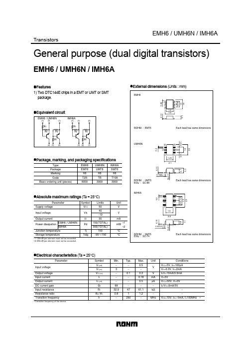
Electrical characteristics (Ta = 25°C)
Parameter Input voltage Output voltage Input current Output current DC current gain Input resistance Resistance ratio Transition frequency
Max. 0.5 − 0.3 0.18 0.5 − 61.1 1.2 −
Unit V V mA µA − kΩ − MHz
Conditions VCC=5V, IO=100µA VO=0.3V, IO=2mA IO/II=10mA/0.5mA VI=5V VCC=50V, VI=0V IO/VO=5mA/5V − − VCE=10V, IE=−5mA, f=100MHz
Appendix1-Rev1.0
元器件交易网
EMH6 / UMH6N / IMH6A
Transistors
General purpose (dual digital transistors)
EMH6 / UMH6N / IMH6A
Features 1) Two DTC144E chips in a EMT or UMT or SMT package. External dimensions (Units : mm)
1.1
0.9
2.0
(5)
(2)
∗
元器件交易网
Appendix
Notes
No technical content pages of this document may be reproduced in any form or transmitted by any means without prior permission of ROHM CO.,LTD. The contents described herein are subject to change without notice. The specifications for the product described in this document are for reference only. Upon actual use, therefore, please request that specifications to be separately delivered. Application circuit diagrams and circuit constants contained herein are shown as examples of standard use and operation. Please pay careful attention to the peripheral conditions when designing circuits and deciding upon circuit constants in the set. Any data, including, but not limited to application circuit diagrams information, described herein are intended only as illustrations of such devices and not as the specifications for such devices. ROHM CO.,LTD. disclaims any warranty that any use of such devices shall be free from infringement of any third party's intellectual property rights or other proprietary rights, and further, assumes no liability of whatsoever nature in the event of any such infringement, or arising from or connected with or related to the use of such devices. Upon the sale of any such devices, other than for buyer's right to use such devices itself, resell or otherwise dispose of the same, no express or implied right or license to practice or commercially exploit any intellectual property rights or other proprietary rights owned or controlled by ROHM CO., LTD. is granted to any such buyer. Products listed in this document use silicon as a basic material. Products listed in this document are no antiradiation design.
南京苏曼电子有限公司科罗纳实验室产品说明书
科罗纳实验室(CORONA LAB.)Please refer to the manual in detail before installing, operating and debugging.安装,操作或调试设备前,请先详细阅读本说明一.概述南京苏曼电子有限公司始建于1983年。
二十几年来一直致力于低温等离子体(电浆)技术的理论研究和材料表面改性处理技术的产品开发,成熟的掌握了各种低温等离子体的实现方法和辉光放电、电晕放电、电弧放电、等产生低温等离子体的工艺技术和知识产权。
并将谐振型脉宽调制技术、微程序控制技术、数字信号处理技术、模糊程序控制等现代先进技术融合在苏曼公司的系列产品之中。
使苏曼公司推出的相关产品实现了电路数字化、软件模糊化、结构模块化、产品系列化。
在体积、效率、功率、可靠性、外观、可操作性及系列方面在国内都处于领先水平。
尤其在价格和易用性方面更具中国特色。
苏曼公司创建的科罗纳实验室(CORONA Lab.)现在已经成为国内最具技术实力的低温等离子体技术和表面处理技术相关产品的研发基地。
推出了十几款用于各种材料和形状的表面改性处理系列产品和大功率臭氧电源,成功的推动了我国高分子材料表面改性处理技术的发展和设备的更新换代。
苏曼公司对各种高分子和金属材料所制成的薄膜、片材、二维和三维零件、高分子和金属材料的复合零件都有对应的表面处理产品。
对印刷、吹膜、复合、流延、涂覆、胶结、真空镀铝、编织布、化纤布、无纺布、片材、管材、合成纸、粉粒等表面处理也有其对应的解决方案。
另外,我们还可为高等院校和研究院所设计和定制用于表面聚合、表面接枝、金属渗氮、冶金、表面催化、化学合成和气液态污染物的处理等各种低温等离子体的处理设备和实验装置。
目前在线生产的系列产品有、ZW-A,CTE-K,CTR(薄膜表面处理系列)、CTT-K,CTT-F (供暖管,天然气管,石油管等内外管壁PE表面处理系列)、CTB(冰箱盖处理),CTD,CTD-K,RFD,RFD-F(二维和三维零件表面处理系列)、CTP(低温等离子体实验仪器仪表系列)、CTK (片材处理系列)、HPD系列次大气辉光放电低温等离子表面处理系统、CTO(大功率臭氧电源系列)等产品系列。
uniohm(贴片电阻)

<50mΩ 2A 5A 150V 300V 500V
1Ω-10MΩ 0.1Ω ---33MΩ 0.1Ω ---33MΩ 0.1Ω ---100MΩ
<50mΩ 2A 10A 200V 400V 500V
1Ω-10MΩ 0.1Ω ---33MΩ 0.1Ω ---33MΩ 0.1Ω ---100MΩ
<50mΩ 2A 10A 200V 500V 500V
STANDARD E-96 VALUES AND 0603 RESISTANCE CODE Ω VALUE 100 102 105 107 110 113 115 118 121 124 127 130 133 137 140 143 147 150 154 158 162 165 169 174 CODE 01 02 03 04 05 06 07 08 09 10 11 12 13 14 15 16 17 18 19 20 21 22 23 24 Ω VALUE 178 182 187 191 196 200 205 210 215 221 226 232 237 243 249 255 261 267 274 280 287 294 301 309 CODE 25 26 27 28 29 30 31 32 33 34 35 36 37 38 39 40 41 42 43 44 45 46 47 48 Ω VALUE 316 324 332 340 348 357 365 374 383 392 402 412 422 432 442 453 464 475 487 499 511 523 536 549 CODE 49 50 51 52 53 54 55 56 57 58 59 60 61 62 63 64 65 66 67 68 69 70 71 72 Ω VALUE 562 576 590 604 619 634 649 665 681 698 715 732 750 768 787 806 825 845 866 887 909 931 953 976 CODE 73 74 75 76 77 78 79 80 81 82 83 84 85 86 87 88 89 90 91 92 93 94 95 96
欧姆杰电磁器件有限公司产品说明书
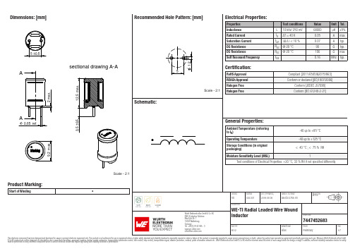
Dimensions: [mm]sectional drawing A-AScale - 2:1Product Marking:Start of Winding•7447452683744745268374474526837447452683T e m p e r a t u r eT T T 7447452683Cautions and Warnings:The following conditions apply to all goods within the product series of WE-TI of Würth Elektronik eiSos GmbH & Co. KG:General:•This electronic component was designed and manufactured for use in general electronic equipment.•Würth Elektronik must be asked for written approval (following the PPAP procedure) before incorporating the components into any equipment in fields such as military, aerospace, aviation, nuclear control, submarine, transportation (automotive control, train control, ship control), transportation signal, disaster prevention, medical, public information network, etc. where higher safety and reliability are especially required and/or if there is the possibility of direct damage or human injury.•Electronic components that will be used in safety-critical or high-reliability applications, should be pre-evaluated by the customer. •The component is designed and manufactured to be used within the datasheet specified values. If the usage and operation conditions specified in the datasheet are not met, the wire insulation may be damaged or dissolved.•Do not drop or impact the components, the component may be damaged.•Würth Elektronik products are qualified according to international standards, which are listed in each product reliability report. Würth Elektronik does not warrant any customer qualified product characteristics beyond Würth Elektroniks’ specifications, for its validity and sustainability over time.•The customer is responsible for the functionality of their own products. All technical specifications for standard products also apply to customer specific products.Product specific:Soldering:•The solder profile must comply with the technical product specifications. All other profiles will void the warranty.•All other soldering methods are at the customers’ own risk.Cleaning and Washing:•Washing agents used during the production to clean the customer application might damage or change the characteristics of the wire insulation, marking or plating. Washing agents may have a negative effect on the long-term functionality of the product. Potting:•If the product is potted in the costumer application, the potting material might shrink or expand during and after hardening. Shrinking could lead to an incomplete seal, allowing contaminants into the core. Expansion could damage the components. We recommend a manual inspection after potting to avoid these effects. Storage Conditions:• A storage of Würth Elektronik products for longer than 12 months is not recommended. Within other effects, the terminals may suffer degradation, resulting in bad solderability. Therefore, all products shall be used within the period of 12 months based on the day of shipment.•Do not expose the components to direct sunlight.•The storage conditions in the original packaging are defined according to DIN EN 61760-2.•The storage conditions stated in the original packaging apply to the storage time and not to the transportation time of the components. Packaging:•The packaging specifications apply only to purchase orders comprising whole packaging units. If the ordered quantity exceeds or is lower than the specified packaging unit, packaging in accordance with the packaging specifications cannot be ensured. Handling:•Violation of the technical product specifications such as exceeding the nominal rated current will void the warranty.•Applying currents with audio-frequency signals might result in audible noise due to the magnetostrictive material properties. •Due to heavy weight of the components, strong forces and high accelerations might have the effect to damage the electrical connection or to harm the circuit board and will void the warranty.•Please be aware that products provided in bulk packaging may get bent and might lead to derivations from the mechanical manufacturing tolerances mentioned in our datasheet, which is not considered to be a material defect.•The temperature rise of the component must be taken into consideration. The operating temperature is comprised of ambient temperature and temperature rise of the component.The operating temperature of the component shall not exceed the maximum temperature specified.These cautions and warnings comply with the state of the scientific and technical knowledge and are believed to be accurate and reliable.However, no responsibility is assumed for inaccuracies or incompleteness.Würth Elektronik eiSos GmbH & Co. KGEMC & Inductive SolutionsMax-Eyth-Str. 174638 WaldenburgGermanyCHECKED REVISION DATE (YYYY-MM-DD)GENERAL TOLERANCE PROJECTIONMETHODTRi002.0072019-08-05DIN ISO 2768-1mDESCRIPTIONWE-TI Radial Leaded Wire WoundInductor ORDER CODE7447452683SIZE/TYPE BUSINESS UNIT STATUS PAGEImportant NotesThe following conditions apply to all goods within the product range of Würth Elektronik eiSos GmbH & Co. KG:1. General Customer ResponsibilitySome goods within the product range of Würth Elektronik eiSos GmbH & Co. KG contain statements regarding general suitability for certain application areas. These statements about suitability are based on our knowledge and experience of typical requirements concerning the areas, serve as general guidance and cannot be estimated as binding statements about the suitability for a customer application. The responsibility for the applicability and use in a particular customer design is always solely within the authority of the customer. Due to this fact it is up to the customer to evaluate, where appropriate to investigate and decide whether the device with the specific product characteristics described in the product specification is valid and suitable for the respective customer application or not.2. Customer Responsibility related to Specific, in particular Safety-Relevant ApplicationsIt has to be clearly pointed out that the possibility of a malfunction of electronic components or failure before the end of the usual lifetime cannot be completely eliminated in the current state of the art, even if the products are operated within the range of the specifications.In certain customer applications requiring a very high level of safety and especially in customer applications in which the malfunction or failure of an electronic component could endanger human life or health it must be ensured by most advanced technological aid of suitable design of the customer application that no injury or damage is caused to third parties in the event of malfunction or failure of an electronic component. Therefore, customer is cautioned to verify that data sheets are current before placing orders. The current data sheets can be downloaded at .3. Best Care and AttentionAny product-specific notes, cautions and warnings must be strictly observed. Any disregard will result in the loss of warranty.4. Customer Support for Product SpecificationsSome products within the product range may contain substances which are subject to restrictions in certain jurisdictions in order to serve specific technical requirements. Necessary information is available on request. In this case the field sales engineer or the internal sales person in charge should be contacted who will be happy to support in this matter.5. Product R&DDue to constant product improvement product specifications may change from time to time. As a standard reporting procedure of the Product Change Notification (PCN) according to the JEDEC-Standard inform about minor and major changes. In case of further queries regarding the PCN, the field sales engineer or the internal sales person in charge should be contacted. The basic responsibility of the customer as per Section 1 and 2 remains unaffected.6. Product Life CycleDue to technical progress and economical evaluation we also reserve the right to discontinue production and delivery of products. As a standard reporting procedure of the Product Termination Notification (PTN) according to the JEDEC-Standard we will inform at an early stage about inevitable product discontinuance. According to this we cannot guarantee that all products within our product range will always be available. Therefore it needs to be verified with the field sales engineer or the internal sales person in charge about the current product availability expectancy before or when the product for application design-in disposal is considered. The approach named above does not apply in the case of individual agreements deviating from the foregoing for customer-specific products.7. Property RightsAll the rights for contractual products produced by Würth Elektronik eiSos GmbH & Co. KG on the basis of ideas, development contracts as well as models or templates that are subject to copyright, patent or commercial protection supplied to the customer will remain with Würth Elektronik eiSos GmbH & Co. KG. Würth Elektronik eiSos GmbH & Co. KG does not warrant or represent that any license, either expressed or implied, is granted under any patent right, copyright, mask work right, or other intellectual property right relating to any combination, application, or process in which Würth Elektronik eiSos GmbH & Co. KG components or services are used.8. General Terms and ConditionsUnless otherwise agreed in individual contracts, all orders are subject to the current version of the “General Terms and Conditions of Würth Elektronik eiSos Group”, last version available at .Würth Elektronik eiSos GmbH & Co. KGEMC & Inductive SolutionsMax-Eyth-Str. 174638 WaldenburgGermanyCHECKED REVISION DATE (YYYY-MM-DD)GENERAL TOLERANCE PROJECTIONMETHODTRi002.0072019-08-05DIN ISO 2768-1mDESCRIPTIONWE-TI Radial Leaded Wire WoundInductor ORDER CODE7447452683SIZE/TYPE BUSINESS UNIT STATUS PAGE。
UniOhm 常用器件规格书总合-7

Derating Curve & Specification
Percent rated load (%)
Type
CS03 CS05 CS06 CS10
Ambient temperature (°C)
Dielectirc Withstanding Voltage
300V 500V 500V 500V 500V
Operating Temperature
-55ºC~155ºC -55ºC~155ºC -55ºC~155ºC -55ºC~155ºC -55ºC~155ºC
CS12
Type CS03 CS05 CS06 CS10 CS12
Power Rating at 70°C 1/10W 1/5W-S 1/8W 1/4W-S 1/4W 1/3W-S 1/2W 3/4W-S 1W
L(mm) 1.60±0.10 2.00±0.15 3.10±0.15 5.00±0.10 6.35±0.10
W(mm) 0.80 1.25 1.55 2.50 3.20
+0.15 - 0.10 +0.15 - 0.10 +0.15 - 0.10 +0.15 - 0.10 +0.15 - 0.10
H(mm)
Temperature cycling Soldering heat Load life in humidity Load life
±(1.0%+0.005Ω) Max. ±(1.0%+0.005Ω) Max. 1%:±(1.0%+0.005Ω) Max. 5%±(3.0%+0.005Ω) Max. 1%:±(1.0#43;0.005Ω) Max.
- 1、下载文档前请自行甄别文档内容的完整性,平台不提供额外的编辑、内容补充、找答案等附加服务。
- 2、"仅部分预览"的文档,不可在线预览部分如存在完整性等问题,可反馈申请退款(可完整预览的文档不适用该条件!)。
- 3、如文档侵犯您的权益,请联系客服反馈,我们会尽快为您处理(人工客服工作时间:9:00-18:30)。
RoHS CompliantAvisert (2) Type [Avisert (2) 型]• This specification is applicable for CFR 1/8W & MFR 1/8W product only; other product (size), please consult factory for the available specifi-cation and drawing.Remark: P 0 cumulative pitch error 1.0mm/20pitch (P 0 累积脚距误差脚距1.0mm / 20脚距)P 1 to be measured at bottom of clinch (P 1 测量固定端底部)t: ground paper 0.5 ± 0.1mm (t: 纸带底厚 0.5 ± 0.1mm )Avisert (1) Type [Avisert (1) 型]• This specification is applicable for CFR 1/4W & MFR 1/4W product only; other product (size), please consult factory for the available specifi-cation and drawing.Avisert TypeBody diameter 本体直径(D) 2.5 Max.Body length 本体长度(L) 6.8 Max.Lead-wire diameter导线直径(d)0.54±0.05Pitch of component零件间距(P)12.7±1Feed hole pitch孔距(P 0)12.7±0.3Hole center to lead孔心至导线中心测量(P 1) 3.85±0.7Lead to lead distance两脚导线中心测量(F)5±1Tape width纸带宽度(W)18±1Hole position孔位(W 1)9±0.5Lead-wire clinch height导线固定端高度(H 0)16.5 ponent height零件高度(H 1)32.25 Max.Lead wire protrusion导线伸出长度(I)1.0 Max.Feed hole diameter孔径(D 0)4±0.3Total tape thickness纸带总厚(t)0.5±0.2Sticky tape width胶带宽度(W 0)12.5 Min.Uncovered paper tape width纸带露出宽度(W 2)3.0 Max.Height of component from tape center零件至纸带中间的高度(H)17.3 ± 0.5Body diameter本体直径(D) 2.5 Max.Lead-wire diameter导线直径(d)0.54±0.05Pitch of component零件间距(P)12.7±1Feed hole pitch孔距(P 0)12.7±0.3Hole center to lead中心测量(P 1) 3.85±0.7Lead to lead distance两脚导线中心测量(F)5±1Component alignment零件偏移(∆h)0 ± 1Tape width纸带宽度(W)18±1Hole position孔位(W 1)9±0.5Lead wire clinch height导线固定端高度 (H)21.0 Max.Component height零件高度(H 1)32.25 Max.Lead wire protrusion导线伸出长度(I)1.0 Max.Feed hole diameter孔径(D 0)4±0.3Total tape thickness纸带总厚(t)0.5±0.2Sticky tape width热熔胶带宽(W 0)12.5 Min.Uncovered paper tape width纸带露出宽度(W 2)3.0 Max.Length of snipped lead剪脚长度(L)11.0 Max.Hole center to component center孔心至零件中心距离(P 2) 6.35 ± 1.3• 适用于 CFR 1/8W 和 MFR 1/8W 固定电阻。
其它产品的立式加工,可洽询工厂以取得可生产的规格图样。
Max. (最大) Min. (最小)Max. (最大) Min. (最小)UniOhm65RoHS CompliantAvisert (3) Type [Avisert (3) 型]• This specification is applicable for CFR 1/4W , MFR1/4W , MOR 1/4W , MOR1WS, MOR2WS, KNP1WS, KNP2WS product only, other product (size), please consult factory for the available specification and drawing.Avisert TypeAdditional Information (注):1=Avisert 1 Type (型)2=Avisert 2 Type (型)3=Avisert 3 Type (型)Resistance Value (阻值):5% (E-24 series): The 1st digit is “0”, the 2nd & 3rd digits are for the significant figures of the resistance and the 4th indicate the number of zeros following5%产品(E-24系列阻值): 第1位数是0,第2、3位数表示阻值的有效数,第4位表示有几个0; ≤2%(E-24,E-96 series): The 1st digit is “0”, the 2nd & 3rd digits are for the significant figures of the resistance and the 4th indicate the number of zeros following≤2%产品(E-24, E-96系列阻值): 第1-3位数表示阻值的有效数,第4位数表示有几个0Ordering Procedure (Example: MFR 1/8W 1% 50PPM 221Ω T/R-5000 Avisert 3 Type)Remark: P 0 cumulative pitch error 1.0mm/20pitch (注: P0 累积脚距误差1.0mm / 20 脚距)Body diameter本体直径(D)1/8W: 2.0 Max. 1/4W: 2.5 Max.Body length 本体长度(L)1/8W: 4.2 Max.1/4W: 6.8 Max.Body height 本体高度(H)1/8W: 7.0 Max.1/4W: 10.0 Max.Lead wire diameter 导线直径(d)1/8W: 0.45 ± 0.051/4W: 0.54 ± 0.05Pitch of component 零件间距(P)12.7 ± 1Lead to lead distance两脚导线中心测量(F)1/8W: 5 ± 11/4W: 5 ± 1Feed hole pitch 孔距(P 0)12.7 ± 0.3Hole center to lead 孔心到导线中心测量(P 1) 3.84 ± 0.7Component alignment 零件偏移(∆h)0 ± 0.1Paper tape widthc 纸带宽度(W)18 ± 1Hold down tape width 孔至下纸带宽度(W 0)12.5 MinHole position 孔位(W 1)9 ± 0.5Hold down tape position 孔至下纸带位置(W 2)3 Max.Lead wire clinch height 导线固定端高度(H 0)16.5 Max.Length of snipped lead 剪脚长度(H 1)11.0 Max.Lead wire protrusion导线伸出长度(I) 1.0 Max.Feed hole diameter 孔径(d 0) 4 ± 0.3Total paper tape thickness 纸带总厚(t)0.5 ± 0.2Max. (最大) Min. (最小)• 适用于 CFR 1/4W , MFR1/4W , MOR 1/4W , MOR1WS, MOR2WS,KNP1WS, KNP2WS 其它产品的立式加工,可洽询工厂以取得可生产的规格图样。
订购方式 (例如: MFR 1/8W 1% 50PPM 221Ω T/R-5000 Avisert 3型)66UniOhm。