思科语音UC500系列产品介绍
UC-5100系列硬件用户手册说明书

UC-5100 Series Hardware User’s ManualEdition 1.1, October 2018/product© 2018 Moxa Inc. All rights reserved.UC-5100 Series Hardware User’s Manual The software described in this manual is furnished under a license agreement and may be used only in accordance withthe terms of that agreement.Copyright Notice© 2018 Moxa Inc. All rights reserved.TrademarksThe MOXA logo is a registered trademark of Moxa Inc.All other trademarks or registered marks in this manual belong to their respective manufacturers.DisclaimerInformation in this document is subject to change without notice and does not represent a commitment on the part of Moxa.Moxa provides this document as is, without warranty of any kind, either expressed or implied, including, but not limited to, its particular purpose. Moxa reserves the right to make improvements and/or changes to this manual, or to the products and/or the programs described in this manual, at any time.Information provided in this manual is intended to be accurate and reliable. However, Moxa assumes no responsibility for its use, or for any infringements on the rights of third parties that may result from its use.This product might include unintentional technical or typographical errors. Changes are periodically made to the information herein to correct such errors, and these changes are incorporated into new editions of the publication.Technical Support Contact Information/supportMoxa AmericasToll-free: 1-888-669-2872 Tel: +1-714-528-6777 Fax: +1-714-528-6778Moxa China (Shanghai office) Toll-free: 800-820-5036Tel: +86-21-5258-9955 Fax: +86-21-5258-5505Moxa EuropeTel: +49-89-3 70 03 99-0 Fax: +49-89-3 70 03 99-99Moxa Asia-PacificTel: +886-2-8919-1230 Fax: +886-2-8919-1231Moxa IndiaTel: +91-80-4172-9088 Fax: +91-80-4132-1045Table of Contents1.Introduction ...................................................................................................................................... 1-1Overview ........................................................................................................................................... 1-2 Model Descriptions .............................................................................................................................. 1-2 Package Checklist ............................................................................................................................... 1-2 Product Features ................................................................................................................................ 1-3 Hardware Block Diagram ..................................................................................................................... 1-3 2.Hardware Introduction...................................................................................................................... 2-1Appearance ........................................................................................................................................ 2-2 LED Indicators .................................................................................................................................... 2-5 Reset Button ...................................................................................................................................... 2-5 Reset to Default Button ....................................................................................................................... 2-5 Real Time Clock .................................................................................................................................. 2-5 Installation Options ............................................................................................................................. 2-6 DIN-Rail Mounting ....................................................................................................................... 2-6Optional DIN-Rail Mounting .......................................................................................................... 2-6 3.Hardware Connection Description ..................................................................................................... 3-1Wiring Requirements ........................................................................................................................... 3-2 Connecting the Power .................................................................................................................. 3-2Grounding the Unit ...................................................................................................................... 3-2 Connecting to the Console Port ............................................................................................................. 3-3 Connecting to the Network ................................................................................................................... 3-3 Connecting to a Serial Device ............................................................................................................... 3-4 Connecting to a DI/DO Device .............................................................................................................. 3-4 Connecting to a CAN Device ................................................................................................................. 3-4 Connecting to a USB Device ................................................................................................................. 3-5 Connecting the Cellular/Wi-Fi Module and Antenna ................................................................................. 3-5 Installing Micro SIM Cards ................................................................................................................... 3-7 Installing the SD Card ......................................................................................................................... 3-8 Adjusting the CAN DIP Switch .............................................................................................................. 3-8 Adjusting Serial Port DIP Switch ........................................................................................................... 3-8 A.Regulatory Approval Statements ....................................................................................................... A-11Introduction The UC-5100 Series embedded computers are designed for industrial automation applications. The computers feature 4 RS-232/422/485 full-signal serial ports with adjustable pull-up and pull-down resistors, dual CAN ports, dual LANs, 4 digital input channels, 4 digital output channels, a SD socket, and a mini PCIe socket for wireless module in a compact housing with convenient front-end access to all these communication interfaces. The following topics are covered in this chapter:❒Overview❒Model Descriptions❒Package Checklist❒Product Features❒Hardware Block DiagramOverviewThe UC-5100 Series embedded computers are designed for industrial automation applications. The computers feature 4 RS-232/422/485 full-signal serial ports with adjustable pull-up and pull-down resistors, dual CANports, dual LANs, 4 digital input channels, 4 digital output channels, a SD socket, and a mini PCIe socket for wireless module in a compact housing with convenient front-end access to all these communication interfaces. Model DescriptionsThe UC-5100 Series includes the following models:•UC-5101-LX: Industrial computing platform with 4 serial ports, 2 Ethernet ports, SD socket, 4 DI, 4 DO, -10 to 60°C operating temperature range•UC-5102-LX: Industrial computing platform with 4 serial ports, 2 Ethernet ports, SD socket, mini PCIe socket, 4 DI, 4 DO, -10 to 60°C operating temperature range•UC-5111-LX: Industrial computing platform with 4 serial ports, 2 Ethernet ports, SD socket, 2 CAN ports,4 DI, 4 DO,-10 to 60°C operating temperature range•UC-5112-LX: Industrial computing platform with 4 serial ports, 2 Ethernet ports, SD socket, mini PCIe socket, 2 CAN ports, 4 DI, 4 DO, -10 to 60°C operating temperature range•UC-5101-T-LX: Industrial computing platform with 4 serial ports, 2 Ethernet ports, SD socket, 4 DI, 4 DO, -40 to 85°C operating temperature range•UC-5102-T-LX: Industrial computing platform with 4 serial ports, 2 Ethernet ports, SD socket, mini PCIe socket, 4 DI, 4 DO, -40 to 85°C operating temperature range•UC-5111-T-LX: Industrial computing platform with 4 serial ports, 2 Ethernet ports, SD socket, 2 CAN ports,4 DI, 4 DO, -40 to 85°C operating temperature range•UC-5112-T-LX: Industrial computing platform with 4 serial ports, 2 Ethernet ports, SD socket, 2 CAN ports, mini PCIe socket, 4 DI, 4 DO, -40 to 85°C operating temperature rangeNOTE The operating temperature range of the wide temperature models is:-40 to 70°C with an LTE accessory installed-10 to 70°C with a Wi-Fi accessory installed.Package ChecklistBefore installing a UC-5100 computer, verify that the package contains the following items:•UC-5100 Series computer•Console cable•Power jack•Quick Installation Guide (printed)•Warranty cardNotify your sales representative if any of the above items are missing or damaged.NOTE The console cable and power jack can be found beneath the molded pulp cushioning inside the product box.Product Features•ARMv7 Cortex-A8 1000 MHz processor•Dual auto-sensing 10/100 Mbps Ethernet ports• 4 software-selectable RS-232/422/485 ports supporting all signals•Dual Industrial CAN 2.0 A/B protocol supported•Moxa Industrial Linux with 10-year superior long term support•Mini PCIe socket for Wi-Fi/Cellular module•Micro SD socket for storage expansion•Supports TPM v2.0 (optional)•-40 to 85°wide temperature range and -40 to 70°C with LTE enabledFor a complete set of specifications, refer to the product datasheet available on the Moxa Website. Hardware Block Diagram2Hardware Introduction The UC-5100 embedded computers are compact and rugged, making them suitable for industrial applications. The LED indicators allow you to monitor performance and identify trouble spots quickly, and the multiple ports can be used to connect a variety of devices. The UC-5100 Series comes with a reliable and stable hardware platform that lets you devote the bulk of your time to application development. In this chapter, we provide basic information about the embedded computer’s hardware and its various components.The following topics are covered in this chapter:❒Appearance❒LED Indicators❒Reset Button❒Reset to Default Button❒Real Time Clock❒Installation OptionsD IN-Rail MountingO ptional DIN-Rail MountingAppearance Front ViewUC-5101UC-5102UC-5111UC-5112Dimensions [units: mm (in)] UC-5101UC-5102UC-5111UC-2112LED IndicatorsThe function of each LED is described in the table below: LED Name Status FunctionPower Green Power is on, and the device is functioning normally OffPower is offReadyYellow OS has been successfully enabled and the device is ready EthernetGreen Steady On: 10 Mbps Ethernet linkBlinking: Data transmission is in progress Yellow Steady On: 100 Mbps Ethernet linkBlinking: Data transmission is in progressOff Transmission speed below 10 Mbps or the cable is not connectedSerial (Tx) Green Serial port is transmitting data Off Serial port is not transmitting data Serial (Rx)Yellow Serial port is receiving data Off Serial port is not receiving dataL1/L2/L3(UC-5102/5112) YellowThe number of glowing LEDs indicates the signal strength. All LEDs: Excellent L1 & L2 LEDS : Good L1 LED : PoorOffNo wireless module detectedL1/L2/L3(UC-5101/5111)Yellow/OffProgrammable LEDs defined by usersReset ButtonThe UC-5100 computer is provided with a Reset button, which is located on the front panel of the computer. To reboot the computer, press the reset button for 1 second.Reset to Default ButtonThe UC-5100 is also provided with a Reset to Default button which can be used to reset the operating system back to the factory default status. Press and hold the Reset to Default button between 7 to 9 seconds to reset the computer to the factory default settings. When the reset button is held down, the Ready LED will blink once every second. The Ready LED will become steady when you hold the button continuously for 7 to 9 seconds. Release the button within this period to load the factory default settings.Real Time ClockThe UC-5100’s real time clock is powered by a non-chargeable battery. We strongly recommend that you do not replace the lithium battery without help from a qualified Moxa support engineer. If you need to change the battery, contact the Moxa RMA service team.Installation OptionsDIN-Rail MountingThe aluminum DIN-rail attachment plate is already attached to the product’s casing. To mount the UC-5100 on to a DIN rail, make sure that the stiff metal spring is facing upwards and follow these steps. Step 1Insert the top of the DIN rail into the slot just below the stiff metal spring in the upper hook of the DIN-rail mounting kit.Step 2Push the UC-5100 towards the DIN rail until theDIN-rail attachment bracket snaps into place.Optional DIN-Rail MountingThe UC-5100 can be mounted with the optional DIN rail mounting kit. Follow these steps for the installation. 1. Attach the optional DIN-rail mounting kit on therear panel with two screws.2. Pull down the slider of the DIN-rail bracketlocated at the back of the unit.3. Insert the top of the DIN rail into the slot justbelow the upper hook of the DIN-rail bracket. 4. Latch the unit firmly on to the DIN rail as shownin the illustrations below.5. Once the computer is mounted properly, youwill hear a click and the slider will rebound back into place automatically.Note this optional DIN-rail mounting kit should be purchased separately.3 Hardware Connection DescriptionIn this chapter, we describe how to connect the UC-5100 to a network and various devices for first time testing purposes.The following topics are covered in this chapter:❒Wiring RequirementsC onnecting the PowerG rounding the Unit❒Connecting to the Console Port❒Connecting to the Network❒Connecting to a Serial Device❒Connecting to a DI/DO Device❒Connecting to a CAN Device❒Connecting to a USB Device❒Connecting the Cellular/Wi-Fi Module and Antenna❒Installing Micro SIM Cards❒Installing the SD Card❒Adjusting the CAN DIP Switch❒Adjusting Serial Port DIP SwitchWiring RequirementsIn this section, we describe how to connect various devices to the embedded computer. Be sure to read and follow these common safety precautions before proceeding with the installation of any electronic device: • Use separate paths to route wiring for power and devices. If power wiring and device wiring paths mustcross, make sure the wires are perpendicular at the intersection point.NOTEDo not run signal or communication wiring and power wiring in the same wire conduit. To avoid interference, wires with different signal characteristics should be routed separately.• You can use the type of signal transmitted through a wire to determine which wires should be kept separate.The rule of thumb is that wiring that shares similar electrical characteristics can be bundled together. • Keep input wiring and output wiring separate.• When necessary, it is strongly advised that you label wiring to all devices in the system.Connecting the PowerTerminal BlockConnect the 9 to 48 VDC power line to the terminal block, which is connector to the UC-5100 Series computer. If the power is supplied properly, the “Power” LED will glow asolid green light. The power input location and pin definition are shown in the adjacent diagram.SG: The Shielded Ground (sometimes called Protected Ground) contact is at the bottomcontact of the 3-pin power terminal block connector when viewed from the angle shown here. Connect the wire to an appropriate grounded metal surface or through the groundingscrew on top of the device.Grounding the UnitGrounding and wire routing help limit the effects of noise due to electromagnetic interference (EMI). Run the ground connection from the ground screw to the grounding surface prior to connecting devices.Connecting to the Console PortThe UC-5100’s console port is a 4-pin pin-header RS-232 port located on the top panel of the case. It is designed for serial console terminals, which are useful for identifying the boot up message, or for debugging when the system cannot boot up.PIN Signal1 -2 - 3GND 4 TxD 5 RxD 6 - 7 - 8-Connecting to the NetworkThe Ethernet ports are located on the front panel of the UC-5100 computers. The pin assignments for the Ethernet port are shown in the following figure. If you are using your own cable, make sure that the pin assignments on the Ethernet cable connector match the pin assignments on the Ethernet port.PinSignal 1 Tx+ 2 Tx- 3 Rx+ 4 – 5– 6 Rx- 7 – 8–Connecting to a Serial DeviceThe serial ports are located on the front panel of the UC-5100 computer. Use a serial cable to connect your serial device to the computer’s serial port. These serial ports have RJ45 connectors and can be configured for RS-232, RS-422, or RS-485 communication. The pin location and assignments are shown in the table below.Pin RS-232RS-422 RS-485 1 DSR - - 2 RTS TxD+ - 3 GND GND GND 4 TxD TxD- - 5RxD RxD+ Data+ 6 DCD RxD-Data- 7 CTS - - 8DTR--Connecting to a DI/DO DeviceThe UC-5100 Series comes with 4 digital inputs and 4 digital outputs. The DI/DO connectors are located on the top panel of the computer. Refer to the diagram on the left for the pin definitions. For the wiring method, refer to the following figure:Connecting to a CAN DeviceThe UC-5111/5112 comes with 2 CAN ports, allowing users to connect CAN device. The pin location and assignments are shown in the following table:PIN Signal 1 CAN_H 2 CAN_L 3 CAN_GND4- 5 - 6 - 7 CAN_GND8-Connecting to a USB DeviceThe UC-5100 Series computers come with a USB port located at the lower part of the front panel, allowing users to connect to a device with an USB interface. The USB port uses a type A connector. Connecting the Cellular/Wi-Fi Module and AntennaThe UC-5102 and UC-5112 computerscome with one Mini PCIe socket forinstalling one cellular or Wi-Fi module.Unfasten the two screws on the rightpanel to remove the cover and find thelocation of the socket.The cellular module package includes 1 cellular module, and 2 screws. The cellular antennas should bepurchased separately to fit your installation requirements.Follow these steps to install the cellular module.1.Set the antenna cables aside for convenience of installation andclear the wireless module socket as shown in the figure.2.Insert the cellular module into the socket and fasten two screws(included in the package) on to the top of the module.We recommended using a tweezer when installing or removingthe module.3.Connect the free ends of the two antenna cables next to thescrews as shown in the image.4.Replace the cover and secure it using two screws.5.Connect the cellular antennas to the connectors.Antenna connectors are located on the front panel of thecomputer.The Wi-Fi module package includes 1 Wi-Fi module, and 2 screws. The antenna adapters and Wi-Fi antennas should be purchased separately to fit your installation requirements.Follow these steps to install a Wi-Fi module.1. Set the antenna cables aside and clear the wireless module socket as shown in the figure for convenience of installation.2. Insert the Wi-Fi module into the socket and fasten two screws (included in the package) on to the top of the module.We recommended using a tweezer when installing or removing the module.3. Connect the free ends of the two antenna cables next to the screws as shown in the image.4. Replace the cover and secure it with two screws.5. Connect the antenna adapters to the connectors on the front panel of the computer.6. Connect the Wi-Fi antennas to the antenna adapters.Installing Micro SIM CardsYou will need to install a Micro SIM card on your UC-5100 computer. Follow these steps to install the Micro SIM card.1. Remove the screw on the cover located on the frontpanel of the UC-5100.2. Insert the Micro SIM card into the socket. Make sureyou place the card in the right direction. To remove the Micro SIM card, simply push the Micro SIM card and release it. Note: There are two Micro SIM card sockets allowing users to install two Micro SIM cards simultaneously. However, only oneMicro SIM card can be enabled for use.UC-5100 Series Hardware Hardware Connection Description 3-8Installing the SD CardThe UC-5100 Series computers come with a socket for storage expansion that allows users to install an SD card. Follow these steps to install the SD card:1. Unfasten the screw and remove the panel cover.The SD socket is located on the front panel of thecomputer.2. Insert the SD card into the socket. Ensure that thecard is inserted in the right direction.3. Replace the cover and fasten the screw on thecover to secure the cover.To remove the SD card, simply push the card in andrelease it.Adjusting the CAN DIP SwitchThe UC-5111 and UC-5112 computers come with one CAN DIP switch for users to adjust the CAN termination resistor parameters. To set up the DIP switch, do the following:1. Find the DIP switch location on the top panel of thecomputer2. Adjust the setting as required. The ON value is 120Ω, and the default value is OFF.Adjusting Serial Port DIP SwitchThe UC-5100 computers come with a DIP switch for users to adjust the pull-up/pull-down resistors for the serial port parameters. The serial port DIP switch is located on the bottom panel of the computer.Adjust the setting as required. The ON setting corresponds to 1KΩ and the OFF setting corresponds to 150KΩ. The default setting is OFF.Each port consists of 4 pins; you must switch all 4 pins of a port simultaneously to adjust the value of the port.A Regulatory Approval StatementsThis device complies with part 15 of the FCC Rules. Operation is subject to the followingtwo conditions: (1) This device may not cause harmful interference, and (2) this devicemust accept any interference received, including interference that may cause undesiredoperation.Class A: FCC Warning! This equipment has been tested and found to comply with the limits for a Class A digital device, pursuant to part 15 of the FCC Rules. These limits are designed to provide reasonable protection against harmful interference when the equipment is operated in a commercial environment. This equipment generates, uses, and can radiate radio frequency energy and, if not installed and used in accordance with the instruction manual, may cause harmful interference to radio communications. Operation of this equipment in a residential area is likely to cause harmful interference in which case the users will be required to correct the interference at their own expense.European Community。
cucm 使用手册

cucm 使用手册CUCM(Cisco Unified Communications Manager)是思科公司研发的统一通信解决方案,它为企业提供了可靠的IP通信服务。
本手册将为您介绍CUCM的基本功能和使用方法,帮助您有效管理和配置您的通信系统。
一、CUCM 概述CUCM 是一种基于IP网络的企业通信系统,它集成了语音、视频、即时消息和移动通信等多种通信功能。
CUCM 可以通过IP电话、软电话、移动电话等各种终端设备实现企业内部和外部的通信。
二、安装与配置1. 硬件要求在部署CUCM之前,您需要确保服务器满足以下要求:至少8GB内存、500GB硬盘空间、支持双核处理器、支持RAID 1磁盘阵列等。
同时还需要安装操作系统和数据库软件。
2. 安装CUCM安装CUCM需要借助启动光盘或USB驱动器。
插入启动介质后,按照屏幕指示进行安装。
安装过程中需要设置管理员账户和密码。
3. 配置CUCM安装完成后,您需要通过Web界面进行CUCM的配置。
首先,输入管理员账户和密码登录系统。
然后,按照系统向导进行配置,包括网络设置、电话用户设置、设备配置等。
三、电话用户管理1. 添加用户登录CUCM管理员界面后,选择“用户管理”,点击“添加新用户”。
按照提示,填写用户的基本信息,例如姓名、工号、电话号码等。
点击“保存”完成用户的添加。
2. 激活用户添加用户后,默认状态是停用,您需要激活用户才能使其正常使用。
在用户列表中勾选要激活的用户,点击“激活”按钮即可。
3. 用户权限管理CUCM支持对用户设置不同的权限,例如管理员、普通用户、访客等。
您可以在用户管理界面设置用户的权限级别,从而实现权限的细化管理。
四、设备管理1. 添加设备在CUCM管理员界面选择“设备”菜单,点击“添加新设备”。
填写设备的基本信息,例如设备类型、设备名称、MAC地址等。
点击“保存”完成设备的添加。
2. 关联设备和用户您可以在设备管理界面关联用户和设备,使用户可以使用特定的设备。
UC500(Technifor打标机)

使用保养手册UC500打标机控制器型号 D C D 01/9627 - U C 500_c n _D - 最新更新版:01/2009材料目录A - 介绍 (3)1. 前言 (3)2. 拆箱 (3)3. 打标装置标识 (4)4. 规则遵守 (4)n 遵守声明 CE (4)n 认可声明 (4)n 符合其他指令声明 (4)n 符合规范声明 (5)5. 工作台建议及安全操作规范 (5)B - 控制器描述 (6)1. 描述 (6)2. 物理特征 (7)3. 技术特征 (7)4. 台式控制器尺寸图 (8)5. 挂壁式控制器尺寸图 (9)6. 可选附件 (10)C - 通讯 (12)1. RS232连线 (12)2. 专用输入/输出 (12)n 阴性SubD 9接头的连线 (12)n 专用输入/输出连接图 (13)n 通讯信号描述 (14)n 通讯信号同步图 (15)3. 通用输入/输出 (18)n 阴性SubD 25接头的连线 (18)n 输入特性 (19)n 输出特性 (20)4. 优盘USB-A (21)D - 投入使用 (22)1. 连线 (22)2. “停止打标”的接线 (22)3. 键盘连接 (22)4. 连接打标头至控制器 (23)5. 电源连接 (23)6. 安装附件 (23)n 安装支脚 (23)n 安装固定板 (24)n 在面板上安装控制器 (25)E - 维修保养 (26)1.更换保险丝 (26)2.常见问题 (26)F - 附件 (27)1. 前言该控制器仅用于运行打标头Technifor。
如果另作它用,Technifor不保证所得结果的质量,对由此可能导致的控制器损坏,Technifor也不负责。
四个图标表示了要点:操作安全标明各种不同预防措施以便安全安装、使用打标机。
使用建议优化本机使用的窍门。
常见问题该图标指向最后一章,介绍了打标机出现问题或故障时应当采取的步骤。
2. 拆箱根据要求,控制器单独包装或随机器包装。
Saramonic Blink 500 ProX B3, B4, B5, B6系列产品说明说明书

Introducing the Saramonic Blink 500 ProX B3, B4, B5, and B6 Systems. The Saramonic Blink 500 ProX B3, B4, B5, and B6 Systems are 2.4GHz wireless systems that deliver exceptional, broadcast-quality sound for 1 or 2 people to Apple iPhones and iPads with Lightning (B3 & B4) or Android Smartphones and Tablets, Computers, and other mobile devices with USB-C (B5 & B6). Ideal for mobile filmmaking, YouTube creators, interviews, vlogging, live streaming, and podcasts. These ultra-portable and incredibly lightweight mic systems come with built-inmics, professional lavalier microphones, a dual-channel device-mountable receiver,and an advanced portable charging carry case. The receivers mount directly to theLightning or USB-C port, providing a digital connection right to the device. They areso compact and lightweight; you can add a powerful wireless system to your devicewithout mounting any bulky accessories or adding significant weight.Upgraded in Every Way: The Industry Original Dual 2.4GHz System Just KeepsGetting BetterThe Blink 500 ProX is the next generation of the immensely successful, and muchcopied Blink 500 Pro system. Combining the innovative features of the originalBlink 500 Pro system with a smaller and lighter updated design, less latency, morereliability, upgraded OLED displays with real-time metering, longer battery life, higherresolution audio signal, wider frequency response, higher signal-to-noise ratio, andeven more new features that set the ProX apart from the original Pro system andcompetitors. While still being incredibly easy to use.B3 & B4 for iPhone & iPad with LightningB5 & B6 for Android Mobile Devices & Computers with USB-CThe Blink 500 ProX systems’ RXDi (B3/B4) and RXUC (B5/B6) dual-channel receiversplug right in and mount to the device’s Lightning or USB-C port. Allowing the systemto work perfectly with your device. A 3.5mm headphone output lets you monitor thesound in real-time, even if your app does not allow real-time monitoring. Absolutelyvital to ensure you’re getting the best sound when recording, and finally allowing youto hear the other participants in virtual meetings, video calls, and online teaching appsin real-time. The receivers also feature a much-desired selectable Mono / Stereooutput setting, giving you the ability either record each mic to separate channels, ormix the mics into your device’s video or audio recording app.Tiny and Light TX Transmitters, with Big and Heavy FeaturesThe Blink 500 ProX TX transmitters feature a built-in omnidirectional microphone withan impressive sensitivity of -39dB. Giving you professional dynamic sound quality ona transmitter small and light enough that you can easily clip it to a shirt or collar. Thetransmitters also include lavalier microphones, allowing you to use them as traditionalbelt pack transmitters for an even more discreet and professional miking solution. Avivid OLED display gives real-time input level metering, and tactile input gain controlsallow you to adjust the audio gain with ease. They also feature a soft-touch mutebutton to quickly mute the transmitter for privacy.SARAMONIC BLINK 500 PROX B3, B4, B5, AND B6 SYSTEMS[CONTINUED]Wireless Transmit Line-Level Audio and Other 3.5mm MicrophonesThe Blink 500 ProX TX transmitters also allow you to transmit line-level signal or microphone-level wirelessly and provide plug-in power to microphones. This stand-out feature makes the system tremendously versatile, allowing you to connect it to virtually any audio source. Switch the TX transmitters to line-level and connect them to mixers, music players, or any line-level device output you want to transmit wirelessly to the receiver. You can use the included SR-M1 lavalier, or you can add a headset microphone, a higher-end lavalier like the Saramonic DK3G, or even plug in a mini-shotgun microphone. Just about any 3.5mm microphone wired for standard TRS pin-out will work, and the adjustable mic gain, and input gain meter lets you get perfect levels every time. Remarkable Power and Convenience for Creators on the MoveThe Blink 500 ProX RXDi and RXUC receivers are battery-free; powered by the device and the transmitters have a battery life ofup to 10-hours. Giving users the ability to shoot for an entire day on one charge! The systems also include either a 2000mAh (B3 & B5) or 3000mAh (B4 & B6) charging carry case that provides multiple additional full system charges for the transmitters, anywhere. Opening the charging case turns the transmitters on and closing the case turns the transmitters off, automatically. Because the transmitters also feature USB-C charging ports, they can be powered while in use or charged outside of the case using USB battery packs or a power supply for even more powering versatility.Features:• Incredibly easy-to-use clip-on wireless mic systems with lavaliers for Lightning or USB-C devices that deliver high-quality sound of up to 2-people to video and audio recordings apps• Incredibly lightweight device-mountable dual receivers sleekly mount on to the Lightning or USB-C port of your device and features Mono/Stereo output setting, and headphone output• Transmitters (TX) have a built-in omni mic and can be clipped to clothing, used as a belt pack with included lavaliers, or transmit line-level audio. They feature OLED display with metering, input level control, and mute• Ultracompact and Lightweight, the systems feature a remarkable 10-hour battery run time on a full charge, 328-feet (100m) line-of-sight range, and automatic channel switching• The transmitters power on and off, automatically when opening and closing the charging case. Case can charge the transmitters up to 3 to 5 additional times anywhere.BLINK 500 PROX B3 INCLUDES:1 x B link 500 ProX TX Transmitter with OLED Display,Built-In Microphone and Clip1 x B link 500 ProX RXDi Dual Lightning Device-MountableReceiver1 × Blink 500 ProX B3 Portable Charging Carry Case1 x SR-M1 Omnidirectional Lavalier Microphone1 x Alligator-Style Lavalier Microphone Clip1 x Foam Lavalier Windscreen1 x F urry High-Wind Press-On Windscreen for Blink 500ProX TX Transmitter1 × Carry Pouch with Accessory Pocket1 x 1’ (30.5 cm) Gold-Plated USB-A to USB-C ChargingCableBLINK 500 PROX B4 INCLUDES:2 x B link 500 ProX TX Transmitter with OLED Display,Built-In Microphone and Clip1 x B link 500 ProX RXDi Dual Lightning Device-MountableReceiver1 × Blink 500 ProX B4 Portable Charging Carry Case2 x SR-M1 Omnidirectional Lavalier Microphone2 x Alligator-Style Lavalier Microphone Clip2 x Foam Lavalier Windscreen2 x F urry High-Wind Press-On Windscreen for Blink 500ProX TX Transmitter1 × Carry Pouch with Accessory Pocket1 x 1’ (30.5 cm) Gold-Plated USB-A to USB-C ChargingCable BLINK 500 PROX B5 INCLUDES:1 x B link 500 ProX TX Transmitter with OLED Display,Built-In Microphone and Clip1 x B link 500 ProX RXUC Dual USB-C Device-MountableReceiver1 × Blink 500 ProX B5 Portable Charging Carry Case1 x SR-M1 Omnidirectional Lavalier Microphone1 x Alligator-Style Lavalier Microphone Clip1 x Foam Lavalier Windscreen1 x F urry High-Wind Press-On Windscreen for Blink 500ProX TX Transmitter1 × Carry Pouch with Accessory Pocket1 x 1’ (30.5 cm) Gold-Plated USB-A to USB-C ChargingCableBLINK 500 PROX B6 INCLUDES:2 x B link 500 ProX TX Transmitter with OLED Display,Built-In Microphone and Clip1 x B link 500 ProX RXUC Dual USB-C Device-MountableReceiver1 × Blink 500 ProX B6 Portable Charging Carry Case2 x SR-M1 Omnidirectional Lavalier Microphone2 x Alligator-Style Lavalier Microphone Clip2 x Foam Lavalier Windscreen2 x F urry High-Wind Press-On Windscreen for Blink 500ProX TX Transmitter1 × Carry Pouch with Accessory Pocket1 x 1’ (30.5 cm) Gold-Plated USB-A to USB-C ChargingCableWhat’s in the BoxThe Saramonic Blink 500 ProX RXDi is an incredibly compact and lightweight device-mountable dual receiver with Lightning output for up to two Blink 500 ProX TX transmitters. It is designed to add a Lightning Receiver to your Blink 500 ProX B1, B2, B5 or B6 wireless systems, and be a spare or replacement for a lost or damaged receiver for your Blink 500 ProX B3 or B4 wireless system. The receiver sleekly mounts into the Lightning port of Apple iPhones and iPads, adding hardly any additional weight or bulk to your iOS device.Includes:1 x Blink 500 ProX RXDi Dual Receiver with Lightning Output1x Printed Manual1x Warranty CardBlink 500 ProX RXUC USB-C Receiver for Blink 500 ProX TXTransmitters for Mobile Devices & ComputersThe Saramonic Blink 500 ProX RXUC is an incredibly compact and lightweight device-mountable dual receiver with USB-C output for up to two Blink 500 ProX TX transmitters. It is designed to add a USB-C Receiver to your Blink 500 ProX B1, B2, B3 or B4 wireless systems, and to be a spare or replacement your Blink 500 ProX B5 or B6 wireless system. The receiver sleekly mounts into the USB-C port of Android Devices, Mobile Devices, and Computers adding hardly any additional weight or bulk to your device.Includes:1 x Blink 500 ProX RXUC Dual Receiver with USB-C Output1x Printed Manual 1x Warranty CardBlink 500 ProX RXDi Lightning Dual Receiver for Blink 500ProX TX Transmitters for iPhones & iPadsBlink 500 ProX RX Dual Receiver for Blink 500 ProX TX Transmitters with TRS & TRRS Output CablesThe Saramonic Blink 500 ProX RX is a remarkably compact and lightweight dual-channel receiver for up to two Blink 500 ProX TX transmitters. It is designed to add a 3.5mm output receiver to your Blink 500 ProX B3, B4, B5 or B6 wireless systems, and be a spare or replacement for lost or damaged receiver for your Blink 500 ProX B1 or B2 wireless system. The receiver comes with both TRS and TRRS output cables and easily slides into the shoe mount of a camera or camera cage. It is so compact and lightweight, you can even clip it to a smartphone, tablet, a camera strap, or anywhere you need a compact dual receiver.Includes:1 x Blink 500 ProX RX Dual Receiver with OLED Display, Built-In Clip and Camera Shoe-Mount1 x 1’ (30.5 cm) Gold-Plated 3.5mm TRS to TRS Output Cable for Cameras1 x 1’ (30.5 cm) Gold-Plated 3.5mm TRS to TRRS Output Cable for Smartphones, Tabletsand Computers1 x 1’ Gold-Plated Micro USB to USB-A Charging Cable1x Printed Manual1x Warranty CardBlink 500 ProX TX Clip-On Transmitter & Lavalier for Blink 500 ProX RX, RXDi and RXUC ReceiversThe Saramonic Blink 500 ProX TX is a compact and lightweight clip-on wireless microphone transmitter with lavalier that is designed to work with the Blink 500 ProX RX, RXDi, and RXUC portable dual receivers. The Blink 500 ProX TX is designed to be a spare or replacement for lost or damaged transmitter, and as a second transmitter to expand your single transmitter Blink 500 ProX B1, B3 or B5 wireless system. Since all the receivers can handle up to two transmitters at the same time, you can expand a single transmitter Blink 500 ProX system with a second Blink 500 ProX TX.Includes::1 x Blink 500 ProX TX Transmitter with OLED Display, Built-In Microphone and Clip1 x SR-M1 Omnidirectional Lavalier Microphone1 x Foam Lavalier Windscreen1 x Furry High-Wind Press-On Windscreen for Blink 500 ProX TX Transmitter1 x 1’ (30.5 cm) Gold-Plated USB-A to USB-C Charging Cable。
思科网真系统 500 系列介绍
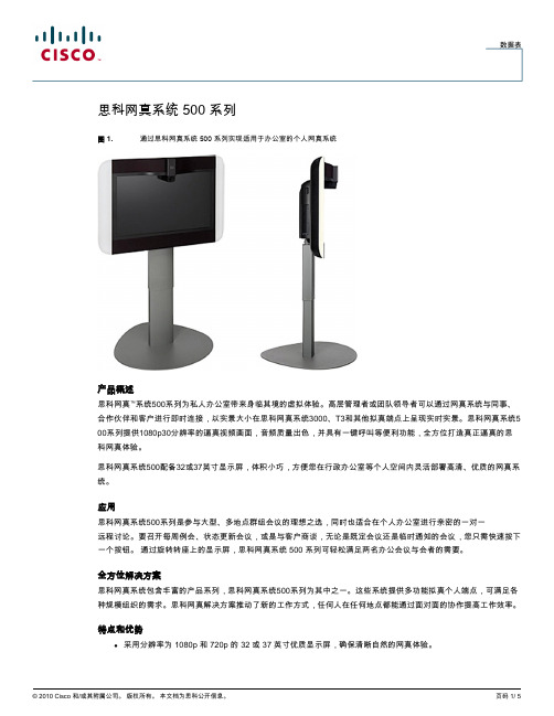
数据表思科网真系统 500 系列图 1. 通过思科网真系统 500 系列实现适用于办公室的个人网真系统产品概述思科网真™系统500系列为私人办公室带来身临其境的虚拟体验。
高层管理者或团队领导者可以通过网真系统与同事、合作伙伴和客户进行即时连接,以实景大小在思科网真系统3000、T3和其他拟真端点上呈现实时实景。
思科网真系统5 00系列提供1080p30分辨率的逼真视频画面,音频质量出色,并具有一键呼叫等便利功能,全方位打造真正逼真的思科网真体验。
思科网真系统500配备32或37英寸显示屏,体积小巧,方便您在行政办公室等个人空间内灵活部署高清、优质的网真系统。
应用思科网真系统500系列是参与大型、多地点群组会议的理想之选,同时也适合在个人办公室进行亲密的一对一远程讨论。
要召开每周例会、状态更新会议,或是与客户商谈,无论是既定会议还是临时通知的会议,您只需快速按下一个按钮。
通过旋转转座上的显示屏,思科网真系统 500 系列可轻松满足两名办公会议与会者的需要。
全方位解决方案思科网真系统包含丰富的产品系列,思科网真系统500系列为其中之一。
这些系统提供多功能拟真个人端点,可满足各种规模组织的需求。
思科网真解决方案推动了新的工作方式,任何人在任何地点都能通过面对面的协作提高工作效率。
特点和优势●采用分辨率为 1080p 和 720p 的 32 或 37 英寸优质显示屏,确保清晰自然的网真体验。
●专门设计的高品质摄像头为用户提供高清影像,眼神交流真实自然;非通话时摄像头将自动缩回,将整个屏幕留作多功能用途(仅 32 英寸选件)。
●全双工 CD 品质音频为用户提供极佳的音频体验,感觉不到延迟,不会受到移动设备或手机的干扰。
●您可以选择开放式麦克风和扬声器,或者添加一副可保护隐私的头戴式耳机;32英寸显示屏的系统集成了二维高级麦克风阵列,以提高音频的清晰度。
●在不用于网真呼叫时,系统可用作辅助的 PC 监控器或数字标牌的视频输出设备。
思科 UCS C480 M5 机架式服务器

© 2017 思科和/或其附属公司。版权所有。
概览 思科公开信息
更多详细信息
有关思科 UCS C480 M5 刀片服务器及所有思科 UCS 服务器的更多详情,请访问 /go/ucs。
产品参数
思科 UCS C480 M5 机架式服务器提供极高的性能 和可靠性,为计算密集型和内存密集型的任务关键 型企业应用以及虚拟化和裸机工作负载提供支持。 其产品参数具体如下: • 最多四个 Intel Xeon 可扩展 CPU 插槽(每个插槽 最多 28 个内核) • 2666-MHz DDR4 内存 • 48 个 DIMM 插槽(每个 CPU 插槽 12 个 DIMM);如果使用 128 GB DIMM,内存容量可 达到 6 TB • 在 2 个 CPU 和 24 个 DIMM 插槽的 CPU 模块中 提供 CPU 和内存 • 12 个 PCIe 3.0 版本插槽 • 最多 24 个小型封装 (SFF) 前置热插拔驱动器(八 组中的三组) • 最多支持 12 个 NVMe 驱动器(每组四个) • 最多 8 个 SFF 顶置热插拔 SAS、SATA 或 NVMe 驱动器 • RAID 控制器选项 • 内部安全数字卡 (SD) 和 M.2 引导选项 • 两个 ASE-T 板载局域网(LOM) 模块 • 具有 3D Xpoint 就绪能力
概览 思科公开信息
思科 UCS C480 M5 机架式服务器
针对任务关键型工作负载提供卓越的性能
思科 UCS® C480 M5 机架式服务器是思科最新推出的 4 插槽任务关键型机架式服务器。它旨在针对 各种内存密集型应用以及裸机和虚拟化工作负载提供行业领先的性能和效率优势。思科 UCS C 系列机 架式服务器既可以作为独立服务器部署,也可以集成到思科统一计算系统™(思科 UCS)。采用集成 部署时,该系列服务器能够利用思科基于标准的统一计算创新成果,帮助客户降低总拥有成本 (TCO) 并提高业务灵活性。 思科 UCS C480 M5 服务器进一步扩展了思科 UCS 机架式服务器产品组合的功能。它采用 Intel® Xeon® 可扩展服务器,与前代产品相比,它的每插槽内核数增加了 14%,存储空间增加 266%, NVMe 固态驱动器 (SSD) 数量增加 10 倍,PCIe 插槽数量增加 20%,支持的 GPU 数量是原来的 3 倍。这些改进在很大程度上提高了产品的性能和效率,有助于实现应用性能提升。如果您追求无比出 色的可扩展性和性能,C480 M5 是您的绝佳选择。
思科统一通信呼叫控制CUCM介绍
信任网络 (不作复杂的安全设置)
Un-trusted
Internet
加密流量 (TLS/SRTP)
IP话机 (远程)
企业总部
IP话机 (内部)
非加密
非加密流量 (TCP/RTP)
Home router w/ NAT
家用路由器/ NAT
ASA Phone Proxy – 远程话机接入
IP Communicator
超过 13,000,000 Cisco IP 话机被售出
Cisco 每个工作日替换掉17,000个传统的模拟话机和数字话机 Cisco 保持了在最近的连续5个季度,每个季度的IP话机的发货量都超过了1,000,000个: 3 years+ to ship 1st million 1 year to ship 2nd million 8 months to ship 3rd million 6 months to ship 4th million 5 months to ship 5th million …and accelerating!
0
%
5
%
1
0
%
1
5
%
2
0
%
2
5
%
3
0
%
Q
4
ユ
0
4
Q
2
ユ
0
5
Q
4
'
0
5
Q
2
'
0
6
Q
4
'
0
6
Q
2
'
0
7
Nortel
Avaya
NEC
SoftCo5500 IP语音综合交换机 产品描述(V100R002C05SPC200_03)
4.1 功能特性....................................................................................................................................................... 16 4.2 业务介绍....................................................................................................................................................... 17
SoftCo5500 IP 语音综合交换机 V100R002C05SPC200
产品描述
文档版本 发布日期
03 2012-01-17
华为技术有ห้องสมุดไป่ตู้公司
版权所有 © 华为技术有限公司 2012。 保留一切权利。
非经本公司书面许可,任何单位和个人不得擅自摘抄、复制本文档内容的部分或全部,并不得以任何形式传 播。
5 操作、维护和管理........................................................................................................................ 21
RTXUC VOIP方案介绍
1.RTXUC融合通信的概念融合通信是指,把传统通信技术与计算机技术融合一体的新的通信模式。
它将传统通信网络与计算机网络融合到同一个网络平台上,实现语音、传真、数据传输、音视频会议、即时通信等众多应用服务,并真正的把通信与企业业务流程结合起来。
2.RTXUC统一通信拓扑结构3.RTXUC统一通信整合界面4.RTXUC VOIP电话系统腾讯通RTX即时通讯平台的VOIP电话插件是一套功能完善的、全面的VOIP系统解决方案。
可智能连通电脑终端、固定电话、移动电话等各类终端设备,方便地提供语音通讯、语音留言、多人通话、即时信息等多种应用体验方式。
RTXUC统一通信IP电话插件的部署,可以使得客户打破空间和地域的限制,只要可以连上网络,登录进入RTX服务器,即可享有方便、快捷的统一通讯应用体验,为广大客户改进企业管理、创新商业模式、提高生成效率、降低运营成本提供强力支持。
5.RTXUC VOIP电话系统组成1)通信服务器整个系统的大脑负责处理所有的呼叫,提供系统的各类通信应用和业务应用嵌入式通信服务器RTXUC1000嵌入式服务器嵌入式板卡模式,可插入G2 媒体网关内部,为中小型机构、企业用户提供一套灵活的基于IP基础网络的语音通信解决方案。
功能特点:- 集成在G2 EU中,全面支持IAD设备、SIP协议IP软/硬件终端- 适用于单点独立系统的部署,也适用于分支机构的远程接入- 即便是远程分支用户,享受总部相同的先进功能规格参数:操作系统和处理器操作系统:Linux处理器:AMD GEODE LX 500MHZ硬件形态形态:嵌入板卡式内存容量大小:256M存储硬盘类型:SAS/SATA硬盘大小:4G容量注册用户:1024支持网关:G2 EU网关,IAD系列语音性能并发呼叫数:240每秒试呼数(CAPS):64BHCC:10KRTXUC3000外置通信服务器外置通信服务器RTXUC3000是一个适于19英寸标准机柜安装的2U高服务器,引入了行业标准服务器,具备更大的存储空间和光驱容量,提供稳定系统性能,适用于中大型分布式和高通信量的机构、企业用户。
思科IP语音平台方案简介-UCM
思科统一通信系统方案建议书(Unified Communication Manager)Cisco System (China)2009.1目录一、语音平台技术要求: (2)二、平台总体建议: (3)三、系统部署和可靠性、安全和QoS: (6)四、IP语音平台编号方案: (10)五、IP智能终端应用举例(可选): (11)六、分机移动服务: (18)七、统一消息服务(可选): (21)八、Web、语音集成会议服务(可选): (24)九、多点视频会议集成(可选): (28)十、IT支持服务中心:(可选) (32)十一、系统维护和管理: (35)十二、思科方案优势: (40)十三、IP语音方案同传统PBX的比较 (45)十四、思科IP智能终端: (47)十五、思科Call Manager系统平台概述: (53)十六、思科IP语音平台安装环境要求: (59)一、语音平台技术要求:项目需求概述:∙为了保证现在和未来业务发展需要,建设融合语音和数据网络的全新通信平台成为通信建设的重点∙新建的办公IP 语音系统应具备支持公司未来三至五年业务发展的能力。
∙系统将覆盖全网各个办公机构。
∙新建的系统将采用纯IP交换方式,同时提供语音信箱、Web会议系统等增值应用平台∙要求新建网络尽可能多的利用现有的思科网络平台∙包括视频集成的多业务通信平台新办公电话通信系统平台:∙覆盖全网的IP电话终端(其中包括彩色触摸屏IP语音终端和黑白大屏IP电话终端;同时提供模拟电话接口用于传真机和模拟电话的连接)。
∙将桌面电话系统同PC进行集成,实现方便的基于PC的呼叫发起和控制。
∙将桌面固定电话同移动终端(如手机)进行捆绑,实现更高效率的通信。
∙各地提供数字中继接入(提供DID接入和传真接入)。
∙电话和Web会议系统(提供语音会议和Web会议)。
∙多媒体信箱系统(提供用户的语音留言功能)。
IP智能终端同OA平台的结合:∙通过IP智能终端的屏幕,集成XML浏览和推送功能,将部分查询和通知功能延伸到每个智能IP终端上。
- 1、下载文档前请自行甄别文档内容的完整性,平台不提供额外的编辑、内容补充、找答案等附加服务。
- 2、"仅部分预览"的文档,不可在线预览部分如存在完整性等问题,可反馈申请退款(可完整预览的文档不适用该条件!)。
- 3、如文档侵犯您的权益,请联系客服反馈,我们会尽快为您处理(人工客服工作时间:9:00-18:30)。
New SB Pro Product Intro
New SB Pro Product Intro
NOV - AP500
SR520-T1 USຫໍສະໝຸດ AP500 WLC 500
• Autonomous APs or Unified Wireless
Solution with Mobility Express
Avaya buying Nortel Need more SB Pro brand awareness ▪ Educate Partners on Why SB Pro
SMB Spring Update © 2006 Cisco Systems, Inc. All rights reserved. Cisco Confidential
New SB Pro Product Intro
NOV-8p ESW
Unified 500 Series 7900 & 500 Series ESW 500 Series
• 8 to 64 Voice Users • Desktop &
Rackmount Models • Optional Integrated WLAN AP on desktop
9/9
SBCS 2.0 10/6 10/13 11/17 12/1 12/1
SMB Spring Update © 2006 Cisco Systems, Inc. All rights reserved. Cisco Confidential
9
Smart Business Communications SystemEX1T.E6/R2N.0AL Portfolio
Cisco is setting Partners up for success to be able to take advantage of market up turn
SMB Spring Update © 2006 Cisco Systems, Inc. All rights reserved. Cisco Confidential
Presentation_ID
© 2006 Cisco Systems, Inc. All rights reserved. Cisco Confidential
1
Agenda
▪ Cisco Unified Communications 500 series, why now? ▪ Roadmap – SBCS 1.6/2.0 ▪ Small Business Pro UC Sales tools ▪ Cisco Small Business Support Center ▪ Competition and positioning ▪ Demo – Cisco Configuration Assistant 2.1
Mitchell1 – Automotive Shop Business Management SW Veramark Call Accounting N-able Remote Monitoring
SMB Spring Update © 2006 Cisco Systems, Inc. All rights reserved. Cisco Confidential
SMB Spring Update © 2006 Cisco Systems, Inc. All rights reserved. Cisco Confidential
2
Executive Summary
Time is now ▪ Complete SB Pro SBCS available by November ▪ Competitors are stumbling- bad press on Microsoft RP,
8
Marketing Launch Dates
Internal Cisco Announce
Disti Announce
Channel Partner Launch
External Public Customer Launch
Partner Virtual Event
SBCS 1.6 7/28 8/4 8/25
SMB Spring Update © 2006 Cisco Systems, Inc. All rights reserved. Cisco Confidential
5
Cisco Small Business Pro Unified Communications 500 Why Now?
SMB Spring Update © 2006 Cisco Systems, Inc. All rights reserved. Cisco Confidential
SCMiscBoSSpMrinBgUUCpdPaotseitionin©g200700620C8isco S©ys2te0m08s,CIniscc.oASll yrisgthetmssr,esInecr.veAdll.rightCs irsecsoerCvoendf.idential Cisco Confidential
▪ IP Telephony ▪ Rich Media Conferencing and Collaboration ▪ Integrated Messaging ▪ Unified Communications Clients ▪ Unified Call Connectors for Industry-leading Applications ▪ Mobility Solutions and Presence ▪ Collaborative Workspaces ▪ Third party Applications Integration
Unified Communications
IP Phones
Switching
Wireless
WAN Security / Teleworker
New SB Pro Product Intro
SEP-UC540 NOUVC-U54C0560
New SB Pro Product Intro
SPA500
4
Cisco Unified Communications for Small Business - Features
Cisco Unified Communications Solutions for Small Business include network powered solutions for:
7
Voice Product Delivery US Timelines
UC520
UC540
FCS
Disti Avail
UC560
SPA500 FCS Phones
Disti Avail
CCA
2.1
FCS
Disti Avail
2.2
Internal EOS
Announce
SMB Spring Update © 2006 Cisco Systems, Inc. All rights reserved. Cisco Confidential
Unified Communications 500 Series - FY10
Helping Your Partners Prepare for Cisco Small Business Pro
Alberto Montilla, Andy Hickman, Ignacio Castroverde, John van Gorp, Jens Demmer
3
“Cisco Unified Communications solutions unify voice, video, data, and mobile applications on fixed and mobile networks, enabling the human network to effectively collaborate every time, everywhere, everyone’s included.”
Cisco SR520
• VPN, Wired and Wireless Access, Remote IP Phone extension
Business & Productivity Applications
Cisco Configuration Assistant
SMB Spring Update © 2006 Cisco Systems, Inc. All rights reserved. Cisco Confidential
ROADMAP 10
Cisco Smart Business Communications System – What’s New in Release 1.6 (SEP)
▪ Cisco UC540 platform in UC 500 Series (NA and EMEA WPL) ▪ Service Offering with Cisco Small Business Support Center ▪ Cisco SR520-T1 WAN Router (NA only) ▪ Cisco SPA500 Series IP Phones ▪ Cisco Configuration Assistant (CCA) version 2.1 ▪ Cisco Smart Designs for SBCS – App Note for Multi-site ▪ Two Additional SIP Trunking Providers ▪ Third Party and Cisco Applications:
11
Cisco Smart Business Communications System – What’s New in Release 2.0 (Nov)