
MWAN3配置手册
MWAN3配置手册
目录
MWAN3配置手册......................................................................................................................... 1 1. 说明 ................................................................................................................................ 2 2. 准备虚拟接口 ................................................................................................................ 2 2.1. 命令行登陆路由器创建虚拟网卡 ......................................................................... 2 2.2.
WEB 管理界面中添加新WAN 接口 (3)
3. 配置MWAN3 ............................................................................................................... 7 3.1. 进入MWAN3管理界面 .. (7)
3.2. 配置MWAN3的接口 (7)
3.3. 配置MWAN3的Members .................................................................................. 10 3.
4. 配置MWAN3的Policies ..................................................................................... 11 3.
5. 配置MWAN3的Rule .......................................................................................... 14 3.
6.
重启MWAN3服务 (14)
4. MWAN3的效果 (16)
W .O
.R
.K
.E
.R
1. 说明
此文档适用于本人在恩山论坛所发帖子
/forum/thread-152506-1-1.html 所对应的固件版本。
其他版本的openwrt 固件可以参考,但不保证完全一样。
此文档是基于我对MWAN3的理解而做,难免有不对的地方,欢迎指正。
2. 准备虚拟接口
2.1. 命令行登陆路由器创建虚拟网卡
1. 用SecureCRT 或putty 登录路由器
2. 编辑/etc/rc.local
vi /etc/rc.local
在“exit 0”之前添加以下内容:
ip link add link eth0.2 name macvlan0 type macvlan ifconfig macvlan0 hw ether FE:BC:51:C4:0A:23 ifconfig macvlan0 up
ip link add link eth0.2 name macvlan1 type macvlan ifconfig macvlan1 hw ether E1:AC:B8:71:E9:B0 ifconfig macvlan1 up
exit 0
说明:
1) 为多拨至少要创建2个虚拟网卡
W .O
.R
.K
.E .R
2) macvlan0和macvlan1为虚拟网卡的名字,可以随意命名
3) mac 地址FE:BC:51:C4:0A:23和E1:AC:B8:71:E9:B0自己随意指定 3. 让虚拟网卡生效
1) 方法1:reboot
2) 方法2:sh /etc/rc.local 3) 验证:ifconfig –a
2.2. WEB 管理界面中添加新WAN 接口
1. 关闭默认WAN 口
登陆WEB 管理页面后,选择“网络->接口”
2. 点WAN 口的修改
3. 在协议处选择不配置协议,并点“切换协议”按钮,再点“保存&应用”按钮
W .O
.R
.K
.E .R
4. 添加第一个基于虚拟网卡的新WAN :VWAN0
1) 返回“网络->接口”页面,点“添加新接口”按钮
2) 填写新接口参数并提交
² 接口名称:VWAN0 --名字自己随便起 ² 协议:
PPPoE
W .O
.R
.K
.E .R
² 以太网适配器:macvlan0 --前面创建好的虚拟网卡 3) 自动进入接口设置页面
填写必要的基本参数,先别提交,再点“防火墙设置”页面
防火墙设置,点“wan ”区,之后点“保存&应用”按钮
4) 如果你的ADSL 线路正常此时网络已经可以连通了,可以在“网络->接口”
页面中看到
W .O
.R
.K
.E .R
5. 按照上面的步骤添加第二个基于虚拟网卡的新WAN :VWAN1
一点重要配置,在接口VWAN1的“高级设置”页面中将“使用网关跃点”改为非0的数值,且与VWAN0的该值不同,如果你打算陪着多个wan 口,该值必须全都不同。
添加好如果线路支持多播后可以在“网络->接口”页面中看到
W .O
.R
.K
.E .R
3. 配置MWAN3
3.1. 进入MWAN3管理界面
选择“网络->Load Balancing ”页面
3.2. 配置MWAN3的接口
1. 在总览页面选择“配置”标签
W .O .R
.K
.E .R
2. 删除一切默认接口,并添加新的接口VWAN0
3. 自动进入VWAN0的细节设置
填写完毕后点“保存&应用”
W .O
.R
.K
.E .R
说明:此页其实需要填写的就是Tracking IP ,也就是mwan3判断该接口是否online 的外ping IP ,我们至少要填写一个,可以写多个,我这里选用了:114.114.114.114和223.5.5.5这两个国内DNS 的IP 4. 同样的步骤添加另一接口VWAN1,完成之后如下图
W .O
.R
.K
.E .R
3.3. 配置MWAN3的Members
1. 点击“Members ”标签进入Members 配置页面
删除全部默认的Members ,在添加框内写入第一个新的Member :vwan0_m1_w1,并按添加按钮
2. 自动进入Member 细节配置页面
W .O
.R
.K
.E .R
1) 接口选择VWAN0 2) 跃点数:1 3) Weight :1
4) 点“保存&应用”
3. 如上述步骤添加另一Member :vwan1_m1_w1
3.4. 配置MWAN3的Policies
1. 点击“Policies ”标签进入Policies 配置页面,删除balanced 之外的其他全部
策略,并点击balance 策略的“修改”按钮
W .O
.R
.K
.E .R
2. 修改balance 策略
1) Member used 按顺序分别选取:vwan0_m1_w1,vwan1_m1_w1 2) 点击“保存&应用”按钮 3. 添加第一个新策略vwan0_only
在添加框内写入策略vwan0_only 并按“添加按钮”
W .O
.R
.K
.E .R
4. 自动进入vwan0_only 的详细配置页面
1) Member used 只选vwan0_m1_w1 2) 点击“保存&应用”
5. 同上添加另一策略
vwan1_only
W .O
.R
.K
.E .R
3.5. 配置MWAN3的Rule
点击“Rule ”标签进入规则配置页面,如果你自己不知道哪种协议从那个链路走的话或者是你配置的WAN 口非常多的话,仅保留default_rule ,剩下的奇偶规则全部删除就可以了。
3.6. 重启MWAN3服务
到此全部配置完毕,但是有可能你在状态页面看到的两个链路都是offline 的,没关系,重启下MWAN3服务就可以了。
W .O
.R
.K
.E .R
1. 点击Advanced 标签进入高级配置页面
2. 点击“网络诊断”标签进入网络诊断页面
点击“Restart MWAN ” 3. 回到总览页面查看状态
W .O
.R
.K
.E .R
4. MWAN3的效果
配置并启用MWAN3后的效果可能并不像想象的那样1+1=2,效果要看你的ISP 限制了,我10mbit 的2播后峰值大概2.53MB 左右,多数都在1.5M 左右,3播后峰值也没达到30mbit ,但会比2拨好一点,再多拨就没尝试了。
W .O
.R
.K
.E .R。
安奈特三层交换机配置手册

安奈特三层交换机配置手册AlliedWare Plus TM OSHow T o |IntroductionThis How T o Note introduces a number of commonly-used management features of the AlliedWare Plus TM operating system (OS), the next generation operating system for Allied T elesis, Inc’s high performance layer 3 managed switches.ContentsIntroduction (1)Contents (1)Related How T o Notes (2)Which products and software version does it apply to? (2)Important differences between the AlliedWare OS and the AlliedWare Plus OS (3)How to log in (4)How to get command help (5)How to work with command modes (9)How to see the current configuration (14)Default settings (15)The default configuration script (16)How to change the password (17)How to set a management IP address (17)How to save and boot from the current configuration (18)How to save to the default configuration file (18)How to create and use a new configuration file (18)How to return to the factory defaults (20)How to see systeminformation ....................................................................................................... .. 21Get Started With The AlliedWare Plus TM Operating System IntroductionHow to set system parameters (23)How to change the telnet session timeout (23)How to name the switch (23)How to display a text banner at login (24)How to set the time and date (25)How to show current settings (25)How to set the time and date (25)How to set the timezone (26)How to configure summer-time (26)How to add and remove users (28)Pre-encrypted passwords (29)How to undo settings (30)How to use the no parameter (30)How to use the default parameter (30)How to work with files (31)How to list files (31)How to display the contents of configuration and text files (33)How to navigate through the file system (34)How to copy files (36)How to use the editor (38)How to upgrade the firmware (39)Appendix: Commands available in each mode (40)User Exec mode (40)Privileged Exec mode (41)Global Configuration mode (42)Related How T o NotesY ou may also find the following AlliedWare Plus OS How T o Notes useful:z How To Configure Basic Switching Functionalityz How T o Configure EPSR (Ethernet Protection Switching Ring) to Protect a Ring from Loops Which products and software version does it apply to? This How T o Note applies to the following Allied T elesis switches, running AlliedWare Plus software version 5.2.1 or later:z SwitchBlade x908z x900 seriesImportant differences between the AlliedWare OS and the AlliedWare Plus OS Important differences between the AlliedWare OS and the AlliedWare Plus OSThe most noticeable differences between the AlliedWare Plus and AlliedWare OSes are:z The command mode hierarchy. With the AlliedWare Plus OS, you go into an appropriate mode before entering configuration or monitoring commands.For details of the modes, see "How to work with command modes"on page9.z The style of the commands. Because you go into a configuration mode, the AlliedWare Plus OS already knows that you are entering a configuration command.Therefore, you do not have to begin commands with keywords like create. This means that many commands are shorter.z How the switch identifies values in commands. The AlliedWare Plus OS either has parameter keywords immediately followed by a space and their value (for an example, see "How to add and remove users"on page28), or simply has a series ofspace-separated values (for an example, see "How to set the time and date"on page25). For manycommands, you must enter the values in the correct order. The ? help makes this easy by prompting you for values one at a time.z How to undo an action or remove a setting. Mostly you remove settings by re-entering the configuration command with the keyword no before it. See "How to undo settings"on page30.z The things the command line warns you about. In the AlliedWare Plus OS: z If you try to create an object (such as a user, trigger etc) and an object with that name already exists, the switch overwrites the original object. It does not warn you before doing so.The file copying commands are an example of an exception to this—the switch asks if you want to overwrite the file.z Y ou only get a message telling you that an operation failed, not if it succeeds. If the switch does not display an error message, you can assume the command wassuccessful.z Port numbering. In the AlliedWare Plus OS, switch ports are named port x.y.z (e.g.port1.0.1), where:z the first number (x) is the stack ID numberz the second number (y) is the module number (0 for base ports and higher numbers for XEMs)z the third number (z) is the port number.z Associating VLANs with switch ports. In the AlliedWare Plus OS, VLANs are configured as an attribute of switch ports. T o associate a VLAN with a port, you enter Interface Configuration mode for the port, not for the VLAN. For details and examples,see the following AlliedWare Plus How T o Note: How To Configure Basic SwitchingFunctionality.z Flash compaction. In the AlliedWare Plus OS, Flash compaction takes up to a minute.The command line is unresponsive during this time. Do not power cycle the switch during Flash compaction.How to log in How to log in1.Set the console baud rateSet the baud rate of your terminal emulator to 115200.For bootloader version 1.0.8 and earlier, this is the switch’s default value. Y ou can use a bootloader menu option to change it, but the first time you access the switch, you must use 115200.Note that in bootloader version 1.0.9, the default baud rate will change to 9600.2.Login with manager/friendLike in AlliedWare, the defaults are:username: managerpassword: friendThe switch logs you into User Exec mode. From User Exec mode, you can perform high-level diagnostics (some show commands, ping, traceroute etc), start sessions (T elnet, SSH), and change mode.How to get command helpThe following kinds of command help are available:zlists of valid parameters with brief descriptions (the ? key)z completion of keywords (the T ab key)z error messages for incomplete or incorrect syntaxT o get syntax help, type ? after:z the prompt, to list all commands available in themode you are inz one or more parameters, to list parameters thatcan come next in the partial commandzone or more letters of a parameter, to listmatching parameters Example T o see which commands are available in User Exec mode, enter “?” at the User Exec mode command prompt:awplus>?This results in the following output:X View a list of valid parameters Tip:The AlliedWare Plus OS only displays one screenful of text at a time, with the prompt “--More--” at the end of each screenful. Press the space bar to display the next screenful or the Q key to return to the command prompt.Exec commands:clear Reset functionsdisable Turn off privileged mode commandecho Echo a stringenable Turn on privileged mode commandexit End current mode and down to previous modehelp Description of the interactive help systemlogout Exit from the EXECmstat Show statistics after multiple multicast traceroutesmtrace Trace multicast path from source to destinationping Send echo messagesquit Exit current mode and down to previous moderemote-command Remote stack member command executionshow Show running system informationssh Open an SSH connectiontelnet Open a telnet connectionterminal Set terminal line parameters traceroute Trace route to destinationExample T o see which show commands that start with “i” are available in User Exec mode, enter “?”after show i:awplus>show i?This results in the following output:interface Interface informationip Internet Protocol (IP)ipv6 Internet Protocol version 6 (IPv6)Example T o use the ? help to work out the syntax for the clock timezone command (page26), enter the following sequence of commands:awplus(config)#clock ?summer-time Manage summer-timetimezone Set clock timezoneawplus(config)#clock timezone ?TIMEZONE Timezone name, up to 6 charactersawplus(config)#clock timezone NZST ?minus negative offset (West of Greenwich)plus positive offset (East of Greenwich)awplus(config)#clock timezone NZST plus ?OFFSET Time zone offset to UTC in HH or HH:MM formatawplus(config)#clock timezone NZST plus 12The above example demonstrates that the ? help only indicates what you can type next. Forcommands that have a series of parameters, like clock timezone, the ? help does not makethe number of parameters obvious.X Complete keywordsT o complete keywords, type T ab after part of the command.If only one keyword matches the partial command, the AlliedWare Plus OS fills in thatkeyword. If multiple keywords match, it lists them.Example T o use T ab completion to enter the command show ip dhcp server summary, enter the following commands. We have included “” to show where to type the T ab key—it is not displayed on screen.awplus>show ipas-path-access-list bgp community-listdhcp dhcp-relay domain-listdomain-name extcommunity-list filterforwarding igmp interfaceirdp mroute mvifname-server nat ospfpim protocols riproute rpfawplus>show ip ddhcp dhcp-relay domain-list domain-nameawplus>show ip dhcpbinding pool serverawplus>show ip dhcp server sstatistics summaryawplus>show ip dhcp server summaryX View command messagesThe switch displays the following generic error messages about command input:% Incomplete command—this message indicates that the command requires more parameters. Use the ? help to find outwhat other parameters are available.awplus(config)#interfaceinterface% Incomplete command.% Invalid input detected at '^' marker—this indicates that the switch could not process the command you entered. The switch also prints the command and marks the first invalid character by putting a '^' under it. Note that you may get this error if you enter a command in the wrong mode, as the following output shows.awplus#interface port1.0.1interface port1.0.1^% Invalid input detected at '^' marker.% Unrecognized command—when you try to use ? help and get this message, it indicates that the switch can not provide help on the command because it does not recognise it. This means the command does not exist, or that you have entered it in the wrong mode, as the following output shows.awplus#interface ?% Unrecognized commandThe AlliedWare Plus OS does not tell you when commands are successful. If it does not display an error message, you can assume the command was successful.How to work with command modesThe following figure shows the command mode hierarchy and the commands to use to move to lower-level modes.X User Exec modeUser Exec mode is the mode you log into on the switch.It lets you perform high-level diagnostics (show commands, ping, traceroute etc), start sessions (T elnet, SSH), and change mode.For a list of commands available in this mode, see "User Exec mode"on page40.The default User Exec mode prompt is awplus>.T o change from User Exec to Privileged Exec mode, enter thecommand:awplus>enable Privileged Exec mode is the main mode for monitoring—forexample, running show commands and debugging. FromPrivileged Exec mode, you can do all the commands from User Exec mode plus many systemcommands.For a list of commands available in this mode, see "Privileged Exec mode"on page 41.The default Privileged Exec mode prompt is awplus#.T o change from Privileged Exec to Global Configuration mode,enter the command:awplus>configure terminal From Global Configuration mode, you can configure mostaspects of the switch.For a list of commands available in this mode, see "Global Configuration mode"on page 42.The default Global Configuration mode prompt is awplus(config)#.X Privileged Exec modeX Global Configuration mode Tip:en is a short-cut forenable Tip:conf t is a short-cut forconfigure terminalA number of features are configured by entering a lower-level mode from GlobalConfiguration mode. The following table lists these features.Some protocols have commands in both Global Configuration mode and lower-levelconfiguration modes. For example, to configure MSTP , you use:zGlobal Configuration mode to select MSTP as the spanning tree mode zMST mode to create instances and specify other MSTP settings z Interface Configuration mode to associate the instances with the appropriate ports.X Lower-level configuration modesModeWhat it configures Command Default prompt InterfaceSwitch ports, VLANs, the management Eth port.interface name awplus(config-if)#Class map QoS classes, which isolate and name specifictraffic flows (classes) from all other traffic.(first enable QoS globally with mls qos enable)class-map name awplus(config-cmap)#EPSR Ethernet Protection Switching Ring, a loopprotection mechanism with extremely fastconvergence times.epsr configuration awplus(config-epsr)#Line Console port settings or virtual terminalsettings for telnet.line console 0line vty number awplus(config-line)#Ping poll Ping polling, which checks whether specifieddevices are reachable or not.ping-poll number awplus(config-ping-poll)#Policy map QoS policies, a collection of user-defined QoS classes and the default class.(first enable QoS globally with mls qos enable)policy-map nameawplus(config-pmap)#Policy map classThe QoS actions to take on a class-map, andwhich class-maps to associate with a QoSpolicy.This mode is a sub-mode of Policy map mode.(in Policy map mode)class name awplus(config-pmap-c)#Route map Route maps, which select routes to include or exclude from the switch’s routing table and/or route advertisements.route-map name deny|permit entry-numberawplus(config-route-map)#Router Routing using BGP , IP , IPv6, OSPF , RIP , or VRRP .router protocolother-parametersawplus(config-router)#MST Multiple Spanning T ree Protocol.spanning-tree mst configuration awplus(config-mst)#T rigger T riggers, which run configuration scripts inresponse to events.trigger number awplus(config-trigger)#VLAN databaseVLANs.vlan database awplus(config-vlan)#X Returning to higher-level modesThe following figure shows the commands to use to move from a lower-level mode to ahigher-level mode.Examples T o go from Interface Configuration to Global Configuration mode:awplus(config-if)#exitawplus(config)#T o go from Interface Configuration to Privileged Exec:awplus(config-if)#endawplus#T o go from Privileged Exec to User Exec:awplus#disableawplus>X Entering Privileged Exec commands when in a configuration modeWhen you are configuring the switch, you are likely to want to enter show commands toconfirm the configuration. This can mean you change often between configuration modes andPrivileged Exec mode.However, you can run Privileged Exec commands without changing mode, by using thecommand:doHowever, you cannot use the ? help to find out command syntax when using the docommand.Example T o display information about the IP interfaces when in Global Configuration mode, enter the command:awplus(config)#do show ip int briefThis results in the following output:Interface IP-Address Status Protocoleth0 172.28.8.200 admin up runningvlan1 unassigned admin up running...How to see the current configurationHow to see the current configurationThe current configuration is called the running-config. T o see it,enter the following command in either Privileged Exec mode or any configuration mode:awplus#show running-config T o see only part of the current configuration, enter thecommand:awplus#show running-config |includeThis displays only the lines that contain word .T o start the display at a particular place, enter the command: awplus#show running-config |beginThis searches the running-config for the first instance of word and begins the display with thatline.Tip:show running-config works in all modesexcept User Exec mode.Default settingsWhen the switch first starts up with the AlliedWare Plus OS, it applies default settings and copies these defaults dynamically into its running-config.These default settings mean that the AlliedWare Plus OS:z encrypts passwords, such as user passwordsz records log message priority in log messagesz turns on jumbo frame support for all portsz turns on the telnet server so that you can telnet to the switchz enables the switch to look up domain names (but for domain name lookups to work, you have to configure a DNS server)z turns off L3 multicast packet switching in the swi tch’s hardware. This prevents L3 multicasts from flooding the switch’s CPU in its default state as an L2 switchz sets the maximum number of ECMP routes to 8z turns on RSTP on all ports. Note that the ports are not set to be edge portsz sets all the switch ports to access mode. This means they are untagged ports, suitable for connecting to hostsz creates VLAN 1 and adds all the switch ports to itz allows logins on the serial console portz allows logins on VTY sessions (for telnet etc)z has switching enabled, so layer 2 traffic is forwarded appropriately without further configurationz allocates all the routing table memory space to IPv4 routes (instead of IPv6 routes)z has ports set to autonegotiate their speed and duplex modez has copper ports set to auto MDI/MDI-X modez has all switch ports attached to VLAN 1The default configuration scriptMost of the above default settings are in the form of commands, which the switch copies toits running-config when it first boots up.The switch stores a copy of the default configuration commands in the file default.cfg anduses that file as its default start-up file.For more information about start-up files, see "How to save and boot from the currentconfiguration"on page18.The following figure shows the contents of the default file.Contents of default file Description!An empty comment line (comments begin with an !). service password-encryption!Forces passwords in the script to be encrypted.log record-priority Records log message priority.username manager privilege 15 password 8$1$bJoVec4D$JwOJGPr7YqoExA0GVasdE0Specifies the password for the manager userservice telnet!T urns on the telnet server.ip domain-lookup!Allows domain name lookups.no ip multicast-routing !T urns off L3 multicast packet switching in the switch hardware.maximum-paths 8Sets maximum number of ECMP routes. spanning-tree mode rstp!T urns on RSTP.interface eth0 !A heading for any configuration settings for the management eth0 port. There are no eth0 settings.interface port1.0.1-1.0.24switchportswitchport mode access!Sets each switch port to access mode.interface vlan1!Creates VLAN 1.line con 0 A heading for any configuration settings for the console port.There are no console port settings.line vty 0 32 !end A heading for any configuration settings for VTY sessions. There are no VTY session settings.How to change the password How to change the password T o change the password for the manager account, enter Global Configuration mode and enter the following command:awplus(config)#username manager passwordThe password can contain any printable character and is case sensitive.How to set a management IP addressThis section describes how to set an IP address on the eth0 management port.1.If desired, check the current configurationAfter logging in, enter Privileged Exec mode by using the command:awplus>enableThen check the current configuration by using one of the following commands:awplus#show ip interface eth0 briefThis results in the following output:Interface IP-Address Status Protocoleth0 172.28.8.200 admin up runningawplus#show running-config interface eth0This results in the following output:!interface eth0ip address 172.28.8.200/16!2.Enter Interface Configuration mode for the eth0 interfaceEnter Global Configuration mode and enter the command: awplus(config)#interface eth03.Enter the IP address and maskEnter the command:awplus(config-if)#ip addressFor example, to set the address to 172.28.8.210/16, enter the command:awplus(config-if)#ip address 172.28.8.210/16How to save and boot from the currentconfigurationThis section tells you how to save your configuration and run the saved configuration whenthe switch starts up.Y ou can either:z save the configuration to the switch’s default configuration file (called “default.cfg”). Bydefault, the switch uses that file at start-up.zcreate a new configuration file and set the switch to use the new configuration file atstart-up.How to save to the default configuration fileEnter Privileged Exec mode and enter the command:awplus#copy running-config startup-configThe parameter startup-config is a short-cut for the current boot configuration file, whichwill be the default configuration file unless you have changed it, as described in the nextsection.How to create and use a new configuration fileEnter Privileged Exec mode and enter the command:awplus#copy running-config .cfgExample T o save the current configuration in a file called example.cfg, enter the commandawplus#copy running-config example.cfgT o run the new file’s configuration when the switch starts up, enter Global Configurationmode and enter the command:awplus(config)#boot config-file .cfgExample T o run the commands in example.cfg on startup, enter the command awplus(config)#boot config-file example.cfg1.Copy the current configuration to a new file2.Set the switch to use the new file at startup3.Display the new settingsT o see the files that the switch uses at startup, enter Privileged Exec mode and enter the command:awplus#show bootThe output looks like this:Boot configuration--------------------------------------------------------------------Current software : r1-5.2.1.relCurrent boot image : flash:/r1-5.2.1.relBackup boot image : Not setDefault boot config: flash:/.configs/default.cfgCurrent boot config: flash:/example.cfg (file exists)4.Continue updating the file when you change the configurationWhen you next want to save the current configuration, enter Privileged Exec mode and enter the command:awplus#copy running-config startup-configThe parameter startup-config is a short-cut for the current boot configuration file.。
【NEWIFI】单线多拨OPmwan3通用教程(图片为外连电脑上论坛开看)

【NEWIFI】单线多拨OPmwan3通用教程(图片为外连电脑上论坛开看)这个固件基本上都配置好了,只是需要根据个人情况修改一下参数就可以实现单线多拨。
1、修改wan6的连接类型为pppoe并且写入宽带账号密码。
2、把wan和wan6设置不同的跃点数。
比如说一个5一个8。
3、开启mwan3。
重启路由器,多拨成功。
下面是设置截图,配置文件。
自带的mwan3,这里打勾开启。
通过网络,接口菜单,把自带的wan6改为pppoe类型并且输入你的宽带账号密码。
很多朋友多拨不成功是因为跃点数没写,每一路拨号必须有不同的跃点数。
wan6跟wan这两个拨号接口都连接路由器的wan口。
防火墙规则也要看一眼别错了。
wan6的跃点数改了之后别忘记把默认的wan的跃点数也改一个。
重启,稍等一下多拨就成功了。
如果不想一个一个点,嫌麻烦的话,也有简单方法,把我贴出来的配置文件写进去就行了。
点击,网络,mawan3,高级,network config。
把里面内容换成下面我的代码就行了。
config interface 'loopback'option ifname 'lo'option proto 'static'option ipaddr '127.0.0.1'option netmask '255.0.0.0'config globals 'globals'option ula_prefix '##########/48'config interface 'lan'option ifname 'eth0.1'option force_link '1'option macaddr '###########'option type 'bridge'option proto 'static'option ipaddr '192.168.8.1' option netmask '255.255.255.0' option ip6assign '60'config interface 'wan'option force_link '1'option macaddr '20:76:93:21:02:a5' option proto 'pppoe'option _orig_ifname 'eth0.2' option _orig_bridge 'false'option ifname 'eth0.2'option username '##########' option password '##########' option metric '5'config interface 'wan6'option _orig_ifname '@wan' option _orig_bridge 'false'option proto 'pppoe'option ifname 'eth0.2'option username '##########' option password '##########' option metric '8'config switchoption name 'switch0'option reset '1'option enable_vlan '1'config switch_vlanoption device 'switch0'option vlan '1'option ports '0 1 2 3 6t'config switch_vlanoption device 'switch0'option vlan '2'option ports '4 6t'主要就是改了红色两段。
WNX Ⅲ系列微电脑多功能消谐装置使用说明书
WNX Ⅲ系列微电脑多功能消谐装置使用说明书目录 WNX Ⅲ系列微电脑多功能消谐装置功能简明表‥‥‥‥‥‥‥‥1WNXⅢ/A、WNXⅢ/B使用说明书‥‥‥‥‥‥‥‥‥‥‥‥‥‥‥‥2主要技术特点‥‥‥‥‥‥‥‥‥‥‥‥‥‥‥‥‥‥‥‥‥‥‥‥‥‥‥‥‥‥2结构与工作原理‥‥‥‥‥‥‥‥‥‥‥‥‥‥‥‥‥‥‥‥‥‥‥‥‥‥‥‥‥2安装前检查提示‥‥‥‥‥‥‥‥‥‥‥‥‥‥‥‥‥‥‥‥‥‥‥‥‥‥‥‥‥3安装开孔与接线‥‥‥‥‥‥‥‥‥‥‥‥‥‥‥‥‥‥‥‥‥‥‥‥‥‥‥‥‥3WNXⅢ/C、WNXⅢ/D使用说明书‥‥‥‥‥‥‥‥‥‥‥‥‥‥‥‥4主要技术特点‥‥‥‥‥‥‥‥‥‥‥‥‥‥‥‥‥‥‥‥‥‥‥‥‥‥‥‥‥‥4结构与工作原理‥‥‥‥‥‥‥‥‥‥‥‥‥‥‥‥‥‥‥‥‥‥‥‥‥‥‥‥‥5安装前检查提示‥‥‥‥‥‥‥‥‥‥‥‥‥‥‥‥‥‥‥‥‥‥‥‥‥‥‥‥‥5安装开孔与接线‥‥‥‥‥‥‥‥‥‥‥‥‥‥‥‥‥‥‥‥‥‥‥‥‥‥‥‥‥6时钟操作和显示纪录‥‥‥‥‥‥‥‥‥‥‥‥‥‥‥‥‥‥‥‥‥‥‥‥‥‥‥6通讯参数的设置‥‥‥‥‥‥‥‥‥‥‥‥‥‥‥‥‥‥‥‥‥‥‥‥‥‥‥‥‥7WNX Ⅲ系列微电脑多功能消谐装置功能简明表WNXⅢ/A、WNXⅢ/B使用说明书主要技术特点1. 用途:WNX Ⅲ-10/A、10/B型用于3~10KV,WNX Ⅲ-60/A、60/B型用于35~66KV电网。
2. 功能:能自动消除电网中的1/10次分频、1/7次分频、1/5次分频、1/3次分频、1/2次分频、基频和3次高频谐振的功能;接地时有指示灯显示。
WNX Ⅲ-10B、60B型还设有接地,谐振、故障报警功能。
3. 远动报警型号:WNX Ⅲ-10/B、60/B型,有三对常开接点可接至中央信号指示灯或电铃。
4. 设有双重动作指示:用灯光表示谐振类别,计数器累计消谐总次数。
5. 动作频率范围(Hz):1/10次分频:4.5~5.5;1/7次分频:6.5~8;1/5:9~11;1/3次分频:15~18; 1/2次分频:23~27;基频:48~52;3次高频:145~162(以上动作频率范围系根据清华大学动模试验小组的建议而确定)。
WM3SBSL使用手册 v1.2

WM3SBSL产品使用手册v1.2版本日期备注1.0 2015.08.31 初版1.1 2015.9.30 更新功耗数据1.2 2015.10.30 更新IO说明模块特性a.支持IEEE802.11b/g/n无线标准b.支持WEP、WPA及WPA2加密c.支持UART\PWM\ADC\GPIO\I2C接口d.支持STA\AP\AP+STA等工作模式e.支持一键配置功能f.支持TLS\SSL和mDNS协议g.支持PCB天线或外接天线h.3.3V供电i.尺寸17.7mm*31mm*3.6mm(带屏蔽罩时)1.产品概述(硬件)WM3SBSL是一款支持802.11b/g/n的WiFi模块,可以通过UART口与其他设备进行通信。
模块集成了射频收发机、MAC、基带处理、所有的wifi协议和配置信息及网络协议栈,可广泛用于智能家居设备、远程监控设备、医疗器械等领域。
模块集成ARM Cortex-M4F处理器,最高主频可达200MHz,512KB的SRAM,128KB 的rom以及8Mbits的外扩Flash。
1.1模块基本参数1.1.1Wlan parameter频率范围 2.412 GHz - 2.472 GHz无线标准支持 IEEE 802.11 b/g/n射频功率 802.11b:16dBm 802.11g:15dBm 802.11n:15dBm天线 内置:PCB天线/ 外接:Ipex接口接收灵敏度 802.11b<-90dBm@1Mbps 802.11b<-80dBm@11Mbps 802.11g<-88dBm@6Mbps 802.11g<-70dBm@54Mbps协议栈支持 IPv4, TCP/UDP/FTP/HTTP/HTTPS/TLS/mDNS 数据速率 11M@802.11b, 54M@802.11g, MCS7@802.11n安全性支持 加密标准:WEP/WEPA/WPA2加密算法:WEP64/WEP128/TKIP/AES网络类型 STA/AP/STA+AP/WIFI Direct1.1.2Absolute Maximum RatingsSymbol Description Min. Max. Units Ts Storage temperature -40 125 ℃T A Ambient operating -20 85 ℃temperatureVdd Supply voltage 0 3.6 V Vio Voltage on IO pin 0 3.3 V5 mAI EOS Max DC input current forany non-supply pin1.1.3DC Voltage and currentSpecifications Min. Typ. Max. UnitsVDD 3 3.3 3.6 VVIL(input low voltage) -0.4 0.3*VDD VVIH(input high voltage) 0.7*VDD VDD+0.4 VVOL(output low voltage) -0.4 0.3*VDD VVOH(output high voltage) 0.7*VDD VDD+0.4 VIol@0.4V 4 mAIoh@VDD-0.4V 4 mAPullup strength 10 50 uA Pulldown strength 10 50 uAStandby 60 mA350 mApulse current @TX11b @16dBm 11Mbps350 mApulse current @TX11g @14dBm 54Mbps1.1.4IEEE802.11b modeITEM SpecificationModulation Type DSSS / CCKFrequency range 2412MHz~2472MHzChannel CH1 to CH13Data rate 1, 2, 5.5, 11MbpsTX Characteristics Min Typical Max. Unit Transmitter Output Power16 dBm11bTarget PowerFrequency Error-20 +20 ppm Constellation Error( peak EVM)@ target power-28 -261~11MbpsRX Characteristics Min Typical Max. Unit Minimum Input Level SensitivitydBm1Mbps (FER≦8%)-9511Mbps (FER≦8%)-84dBm-10 dBm Maximum Input Level(FER≦8%)1.1.5IEEE802.11g modeITEM SpecificationModulation Type OFDMFrequency range 2412MHz~2472MHzChannel CH1 to CH13Data rate 6, 9, 12, 18, 24, 36, 48, 54MbpsTX Characteristics Min Typical Max. UnitTransmitter Output Power11gTarget Power14 dBm Frequency Error-20 +20 ppm Constellation Error( peak EVM)@ target power6Mbps -21dB 54Mbps -31dB Transmit spectrum mask@11MHz -20 dBr@20MHz -28 dBr@30MHz -40dBr RX Characteristics Min Typical Max. UnitMinimum Input Level SensitivitydBm 6Mbps -9054Mbps -72 dBm-20 dBm Maximum Input Level(FER≦10%)1.1.6IEEE802.11n 20MHz bandwidth modeITEM SpecificationModulation Type OFDMFrequency range 2412MHz~2472MHzChannel CH1 to CH13Data rate MCS0/1/2/3/4/5/6/7TX Characteristics Min Typical Max. UnitTransmitter Output Power13 dBm 11n HT20 Target PowerFrequency Error-20 +20 ppm Constellation Error( peak EVM)@ target powerdB MCS0 -19MCS7 -30dBTransmit spectrum mask@11MHz -20 dBr @20MHz -28 dBr @30MHz -40 dBrRX Characteristics Min Typical Max. Unit Minimum Input Level SensitivitydBm MCS0 -88MCS7 -69 dBm-20 dBm Maximum Input Level(FER≦10%)1.2硬件介绍1.2.1机械尺寸(单位:mm)1.2.2接口定义管脚接口定义备注Pin1 GNDPin2 VCC 3.3VPin3 RST_N 模块重启,低电平有效.Pin4 UART_TX 仅供透传使用Pin5 UART_RXPin6 GPIO3Pin7 GPIO4Pin8 GPIO4Pin9 GPIO3Pin10 GPIO2Pin11 GPIO1 通常作为模块软件复位,高电平有效Pin12 GPIO0 通常作为wifi指示灯。
艾顿智能3路风扇速度控制器说明说明书

DescriptionSingle pole, 3-way, 1.5A, 120V/AC, 60HzDesign features•Set up and control fan speed control using theEaton Brightlayer Home App or by voice commands • No hub required•LED indicator system alerts if the device is not set up in the network•Preset whether your device comes on or stays off following a power outage• Neutral required for installation•Dimmable white LED indicators illuminate to indicate (ON, OFF) status•Can be wired with standard 3-way switch where traveler wire exists for 3-way.EWFFSC15Project Name:Prepared By:Project Number:Date:Catalog Number:Type:T able 1. Wi-Fi smart fan speed controlCompliances, specifications and availability are subject to change without notice.Rating DescriptionColor suffixCatalog no.AV/AC Hz1.512060Wi-Fi smart fan speed controlW, C2, C6, C7Amazon, Alexa and all related logos are trademarks of , Inc. or its affiliates. Google and Google Play are trademarks of GoogleLLC. Wi-Fi CERTIFIED logo is a trademark of the Wi-Fi Alliance.Wi-Fi smart fan speed control2EATON/connectedhome Technical DataEffective April 2023Wi-Fi smart fan speed controlCatalog No.EWFFSC15PerformanceMaximum amperage: 1.5ARating:120V/AC, 60HzInstallation & programming For installation and programming the device, see the Wi-Fi Smart Fan Speed Control Quick Start Guide included with product.Testing & code compliance cULus Listed 244B. NOM Certified. Complies with FCC Part 15, Class B.TerminationsFan speed controller has screw terminals for line, load, ground, neutral and traveler 3-way wire Material characteristics Flammability: Meets UL94 requirements; V2 rated Temperature rating: 32°F to 104°F (0°C to 40°C)Warranty2-year limited product warrantyEaton’s Wi-Fi smart fan speed control replaces regular switches (where a neutral is present) to provide local and remote control for ceiling fans. The fan speed controller can be remotely controlled and the user can create routines, schedules and group devices using the Eaton Brightlayer Home App. Eaton’s Wi-Fi smart fan speed control has additional features such as a selection of 3 fan speed controls (High, Medium, Low).ApplicationsProject Name:Prepared By:Project Number:Date:Catalog Number:Type:T able 2. SpecificationsCompliances, specifications and availability are subject to change without notice.Figure 1. EWFFSC15For ordering devices, include Catalog No. followed by the Color Suffix: W (White),C2 (Color Change Kit: LA, W, V), C6 (Color Change Kit: W, RB, SG), C7 (Color Change Kit: B, BK, GY)Decorator series color options:(White)C2 Color KitLA (Light Almond), W (White),V (Ivory)C7 Color KitB (Brown), BK (Black), GY (Gray)C6 Color KitRB (Oil Rubbed Bronze), W (White),SG (Silver Granite)T able 3. Color ordering information3EATON /connectedhome Single location control installationWi-Fi smart fan speed control Technical DataEffective April 2023Project Name:Prepared By:Project Number:Date:Catalog Number:Type:Certifications & compliancesKEY:cULusNOMFCCRelated productsWi-Fi smart productsEWFD30, EWACD, EWFTRCR15Compliances, specifications and availability are subject to change without notice.WallplatesPJS26, PJS262Single Location Control Installation (requires one Wi-Fi Fan Speed Control)3-Way location control installation Electrical Sector 1123 Hwy 74 SPeachtree City, GA 30269United States /WifiSmartElectrical Sector Canada Operations 5925 McLaughlin RoadMississauga, Ontario, L5R 1B8CanadaEatonCanada.ca/WifiSmartElectrical Sector Mexico Operations Carr. Tlalnepantla -Cuautitlan Km 17.8 s/n Col. Villa Jardin esq.Cerrada 8 de MayoCuautitlan, Mexico CP 54800Mexico Eaton.mx/WifiSmartEaton1000 Eaton Boulevard Cleveland, OH 44122United States Eaton is a registered trademark. All other trademarks are property of their respective owners.© 2023 EatonAll Rights Reserved Printed in USAPublication No. TD610147EN April 2023。
网瓦Pro-AC3000三带WiFi系统数据表说明书
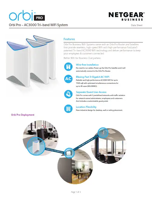
• Simultaneous Tri-band WiFi
• Radio 1: IEEE® 802.11b/g/n 2.4GHz–256QAM support
• Radio 2: IEEE® 802.11a/n/ac 5GHz–256QAM support
SRK60B05-10000S Adds up to 12,500* square feet of mesh WiFi coverage
SRK60B06-10000S Adds up to 15,000* square feet of mesh WiFi coverage
Bundle content include
• Security
• WPA/WPA2-PSK support
• Three (3) wireless networks
--Administrative devices
--Employee devices
--Guest devices with Captive Portal Challenge
• Guest WiFi Network is easy to setup for secure Internet access
NETGEAR, Inc. 350 E. Plumeria Drive, San Jose, CA 95134-1911 USA, /support Page 3 of 3
• MU-MIMO capable for simultaneous d ata streaming on multiple devices
newifi新路由刷潘多拉固件后通过mwan3实现有线+无线宽带叠加教程?
newifi新路由刷潘多拉固件后通过mwan3实现有线+无线宽带叠加教程?这两天就在研究mwan3,能实现有线+无线的宽带叠加,目的是让路由器同时使用自家的网和邻居家蹭来的无线,做到提高上传下载速度!当然,整个步骤可能跟电脑上装个qq难度差不多,但是对我这种初次接触的小白来说还是要折腾一番的,虽然说总算是叠加上了,但感觉过程中还是有点小问题,也不知道是出在我这里还是mwan3或pandorabox本身,把步骤分享出来?先看看叠加的成果,我家和楼上都是电信下行20M上行2M光纤宽带,正常的速度大概是下载2.6Mb/s、上传270Kb/s。
下图分别是叠加后电信测速结果和bt下载速度,可以看到本来就不快的上传妥妥的2+2叠加到了4M,平均下载显示是34.6M,试了下bt下载时最高4.6Mb/s(约37M),虽然没到40M但也相当给力了。
进入正题,mwan3能做的不少,这边只是测试有线跟无线的叠加。
讲具体步骤前先看下整个示意图,注意lan口的ip设置要保证和各wan口的ip段错开。
一、无线桥接。
这是大前提必须要能桥接上并能上网,不然也没有后面叠加的事了。
进入Pandorabox的管理界面→网络→无线,点击2.4g信号右侧的搜索会扫描出附近的其他无线信号,找到要桥接的那个点击加入。
然后会出现设置页,输入这个无线的密码,更改网络名称为wan2。
第一行“重置无线配置”保持默认不勾选,防火墙规则保持默认选wan。
提交后会看到无线下面多了那个桥接的SSID,模式是“Client”。
网络接口下多了之前新增的“wan2”。
我这wan2显示的数据都是0,mac克隆了也不显示,刚开始以为桥接没成功。
后来电脑直接连楼上无线进路由器管理页面看显示newifi是连着的,再回头进Pandorabox把有线的wan口先断开,再开网页发现确实能上网,进电信网络测试显示的也是楼上家的账号,但wan2的数据仍旧显示0,不知道是不是Pandorabox的问题。
Hitron HT-EMN3 扩展网络设备说明书
Hitron’s HT-EMN3offers the ability to extend your wireless network through three possible methods:Ethernet,MoCA or Wi-Fi.Simply connect the HT-EMN3to a coax or Ethernet outlet and it will automatically establish the link and synchronize all Wi-Fi parameters with your Hitron gateway through the AutoSync feature.•4x4 5 GHz 802.11ac Wave 2 and 2x2 2.4 GHz802.11n dual band MU-MIMO internal antennas •8 SSIDs per radio•Individual configuration for each SSID (security,bridging, routing, firewall and Wi-Fi parameters) •MoCA 2.0 Channel bonding for highestperformance •2 GigE ports •Upgradable software over web-based GUI •Hardware DES and AES Encryption to keep your data safe from unauthorized access •MyHitron app is offered for further support (available for Android and iOS devices)•TR-069 for easy setup and remote management Network Extender, Wi-Fi 4x4, MoCA, GigE4x4 5GHz + 2x2 2.4GHz dual band MU-MIMO Wi-Fi,MoCA 2.0 channel bonding and gigabit Ethernet solutionEASY TO INSTALLThe HT-EMN3supports pre-configured and pre-enabled Wi-Fi security via Wi-Fi Protected Setup (WPS),allowing the end-user to rapidly set up a secure wireless network without manual configuration.EASY & SECUREKEY FEATURESThe HT-EMN3integrates Wi-Fi 4T4R 802.11ac 5GHz +2T2R 802.11n 2.4GHz dual band concurrent MU-MIMO access point,MoCA2.0channel bonding and two (2)Giga Ethernet ports.The HT-EMN3enables high-bandwidth traffic to be seamlessly distributed across the end-user’s home or office.HIGH-PERFORMANCE NETWORKINGCoax Wi-Fi Ethernet (GigE)Wi-Fi, MoCA or GigESet-top box TVLaptop Smartphones TabletsTV ThermostatHome Security Hitron Gateway PCPrinter NAS GamingConsole Cable Plant Internet Streamer TV HT-EMN3Connectivity•2x RF F-type female connectors (75Ω)•2x RJ-45 Ethernet ports 10/100/1000Mbps (Auto-MDI/MDIX)Management•AutoSync(with Hitron gateway)•MyHitron app support•Protocol support: TR-069, SNMP v1, v2C, and v3•Web-based GUI control, configuration and management •Easy-to-read LEDs clearly display network status and activityMoCA 2.0 Reception / Transmitter-Modulation•MoCA 2.1, 2.0, 1.1 and 1.0 standards•Beacon band: D1, D2, D3, D4, D5, D6, D7, D8, D9, D10•Primary channels: 1175MHz, 1200MHz, 1225MHz, 1250MHz, 1275MHz, 1300MHz, 1325MHz, 1350MHz, 1375MHz,1400MHz, 1425MHz, 1450MHz, 1475MHz, 1500MHz •Demodulation/Modulation: BPSK, QPSK, 8QAM, 16QAM,32QAM, 64QAM, 128QAM, 256QAM, 512QAM, 1024QAM •Data rate: 700Mbps (baseline Mode) / 1400Mbps (bonding channel)•Throughput: 400+Mbps (baseline Mode) / 500+Mbps (baseline mode, point to point) / 800+Mbps (bonding channel) / 1000Mbps (bonding channel, point to point)•Frequency range: 1125-1675MHz•Channel bandwidth: 100MHz (baseline mode) / 225MHz (bonding channel)•Link privacy: 56-bit DES and 128-bit AES hardware encryptions for network security and password•Max number of network nodes: 16Compliance Certificates•FCC, IC•RoHS compliant Wireless•802.11a/b/g/n/ac•2T2R 802.11n 2.4GHz + 4T4R 802.11ac 5GHz dual band concurrent MU-MIMO with 300Mbps+1733Mbps PHY data rate •Frequency range: 2.412~2.4835 GHz and 5.18~5.825GHz •Channel bandwidth: 20/40/80/160MHz•Up to 8 SSIDs for each frequency•Security: WEP-64/WEP-128, WPA-PSK/WPA2-PSK (TKIP/AES)•QoS: WMM/WMM U-APSD, Airtime Fairness management •WPS (Wi-Fi Protected Setup) PBC, PIN•Output power range:•2.4G (EIRP)22.01dBm•5G Uni 1 (EIRP)23.02dBm•5G Uni 2 (EIRP)26.02dBm•5G Uni 3 (EIRP)26.02dBm•5G Uni 4 (EIRP)26.02dBm•Fast roaming: 802.11r, 802.11k, 802.11v•Supports band steeringMechanical•6 status LEDs (Power, MoCA, LAN, 2.4G Wi-Fi, 5G Wi-Fi, WPS)•Possibility to turn off LEDs on specific time via Web UI •WPS button•Factory reset button•Dimensions: 171mm (W) * 171mm(D) * 51.5mm(H) •Weight: 460g ±10gElectrical•Power input: DC 12V / 2A•Power adapter: 100-240VAC to DC 12V, 50/60Hz•Power consumption: 24W (Maximum)•Surge protection: RF input sustains at least 4KV,Ethernet RJ-45 sustains at least 4KVEnvironmental•Operating temperature: 0°C (32°F) -40°C (104°F)•Operating humidity: 10% -90% (non-condensing)•Storage temperature: -30°C (-22°F) -70°C (158°F)SPECIFICATIONS。
MWAN3配置手册
MWAN3配置手册目录MWAN3配置手册......................................................................................................................... 1 1. 说明 ................................................................................................................................ 2 2. 准备虚拟接口 ................................................................................................................ 2 2.1. 命令行登陆路由器创建虚拟网卡 ......................................................................... 2 2.2.WEB 管理界面中添加新WAN 接口 (3)3. 配置MWAN3 ............................................................................................................... 7 3.1. 进入MWAN3管理界面 .. (7)3.2. 配置MWAN3的接口 (7)3.3. 配置MWAN3的Members .................................................................................. 10 3.4. 配置MWAN3的Policies ..................................................................................... 11 3.5. 配置MWAN3的Rule .......................................................................................... 14 3.6.重启MWAN3服务 (14)4. MWAN3的效果 (16)W .O.R.K.E.R1. 说明此文档适用于本人在恩山论坛所发帖子/forum/thread-152506-1-1.html 所对应的固件版本。
Manu3 手表面测量系统用户手册说明书
Portable contactless hand measurement system Manu3 unit User Manual© 2016 Anatomi MetrixTable of ContentsINSTALLATION 2 PRODUCT DESCRIPTION 3 CAPTURING AN IMAGE WITH MANU3 4 HAND POSITIONING GUIDELINES 6 MAINTENANCE 7 PRODUCT SPECIFICATIONS & CERTIFICATIONS 8ForewordManu3 is a portable hand measurement instrument. Its intended use is to measure the required dimensions to select or manufacture gloves or cosmetic covers.This manual covers the use of the Manu 3 unit. For more information on the M3M measurement software, consult the M3M User Manual.Safety PrecautionsDO NOT CONNECT to a power outlet without a proper ground connection.Manu3 can receive 115V or 230V input voltage. Before use, make sure that THE PROPER VOLTAGE is selected at the back of the unit, right below the power supply outlet.DO NOT IMMERSE Manu3 in liquid or spray any liquids directly on or in the Manu3 unit.Installation∙Make sure the unit was not damaged during transport. Do not connect a damaged unit.∙Remove the unit and its power cord from the box and place the unit on a flat surface.∙Connect the unit to a power outlet in compliance with the safety precautions.∙The unit is ready for use, no calibration required.Product Description1.Manu3 unit2.Power cordB keySafe handle for lifting and carrying Flat surface for hand placementPower supply connector ArmrestPower on button USB portTouchscreen with controlsManu3 is a hand measurement system composed of a portable unit and power cord (1 and 2) and a USB key (3) with the M3M measurement software and installation package.The portable unit can capture, store and export through a USB port images taken of a person’s hand. The M3C software pre-installed on all Manu3 units tags the images with a unique id number. The measurement software, M3M, facilitates the selection of all relevant points for measuring lengths and circumferences of the hand. The results can be visualized as reports and exported as odt or cvs report files.Capturing an image with Manu31.Power on the unit. This can take up to a few minutes.2.The home page screen is displayed.Start acquiring images of the hand3.Enter the patient’s name in the textbox with the keyboard or select an existing patientID from the dropdown arrow.Go to the Capture screenHome page screen can be accessed at anytime using the top left corner icon.2. A live image is displayed. Use theimage on the left and the HandPositioning Guidelines (followingsection) to place the handappropriately inside the unit.Hand placement influences thequality of the measurements.When the position is right, ask the person to remain still.Image is captured and stored in M3C’s internal memory5.Review the still image taking the guidelines into consideration:If the image is accepted, export the image on display1If more images are needed, this will save the current image and go backto live image acquisitionIf the image is rejected, delete the image on display and go back to liveimage acquisition∙To retrieve images previously captured and stored in Manu3’s internal memory:This will give you access to images of the same person or ID number ∙To capture images with a different ID number:This will allow you to enter a new name or select an already existing ID6.To shut down the unit, go back to the home screen.Turn off the unit.1The USB button is only active when a USB key is detected.Hand Positioning Guidelines∙Before capturing an image:⨯Remove all jewelry such as rings, watches and bracelets⨯Remove, as much as possible, bandages or dressings∙DO’s: Optimal hand positioning guidelines✓The middle finger, wrist and lower arm should all be aligned✓The thumb and middle finger should be spread at a 35 to 45° angle✓The fingers should be spread evenly but not so much as to cause discomfort✓The beginning of the wrist should lie 1 to 3 cm past the armrest✓The hand and the fingers should be kept flat on the surface as much as possible ∙DON’T’s: things to look for and avoidWrist positioning⨯Wrist outside the groove of the armrest ⨯Wrist too close to the armrestFinger positioning⨯Fingers are not spread evenly ⨯Finger outside of the capture areaThumb positioning⨯Thumb is at an angle, it must be kept straight ⨯Thumb is not spreadenoughMaintenanceManu3 contains no serviceable parts and should not be opened in order to preserve safe use and warranty of the product.To clean Manu3’s exterior and bottom plate use household type soft soap and a soft wet cloth. The armrest can be removed and cleaned using soft soap.To change the date or time of image acquisition, go to the Home page screen.This menu gives access to some Manu3 settings:S ystem’s t ime and date will be displayed, change if necessaryThis function shouldn’t be used since the unit is pre-calibrated.Only use if advised to do so by an Anatomi Metrix representative. If the power cord supplied with the unit is damaged or missing, please contact Anatomi Metrix for an authorized replacement power cord.Important Note: This device contains Lithium batteries that should be disposed of in an environmentally friendly manner, The European Battery Directive 2006/66/EC applies to this device.To contact Anatomi Metrix service department for support:By Email: ********************By Telephone: 514-882-9676Product SpecificationsCertificationsCAN/CSA C22.2#61010-1o Issued: 2012/05/11 Safety Requirements for Electrical Equipment for Measurement, Control, and Laboratory Use Part 1: General RequirementsUL 61010-1o Issued: 2012/05/11 Ed:3 Safety Requirements for Electrical Equipment for Measurement, Control, and Laboratory Use Part 1: General RequirementsCENELEC EN 61010-1 Co Issued: 2010/10/01 Ed:3 Safety Requirements for Electrical Equipment for Measurement, Control, and Laboratory Use Part 1:General RequirementsCENELEC EN 61326-1o Issued: 2013/01/01 Electrical Equipment for Measurement, Control andLaboratory Use – EMC Requirements - Part 1: General Requirements。