梅兰日兰UPS使用操作说明
梅兰日兰UPS通信板的使用

P O W E R
P R O V I D E R
GALAXY 5000的原理:选件通信板
Installation notice cuttings of the Network management card
T H E
U N I N T E R R U P T I B L E
P O W E R
P R O V I D E R
Multislot
热拔插
xxxx Meta UPS 卡
P R O V I D E R
66 074 网络管理卡
T H E
U N I N T E R R U P T I B L E
P O W E R
GALAXY 5000的原理:SECI板
SECI板的所有报警:
充电器重大故障组 或 电池电路 或 连接故障 或 UPS 中的参数设置码不一致 UPS 之间的CAN通信故障 或 电路板之间的 CAN 通信故障 (GDEN, MIZN 和 CHAN) 或 CAN 电缆物理断开 或 参数设置被某一块电路板拒绝 或 电池充电不及时 或 电池深度放电故障 或 直流母线电压达到最高值 或 EPO on the CHAN 或 电池后备时间结束,转入休眠模式 或 主交流电源频率超限 或 主交流电源保险故障 或 给ALIZ 板供电的直流保险故障 或 主交流输入电源电流限流和低电压 或 中线支路重大故障组 或 主交流电源缺一相 或 Q3BP 和 Q5N 闭合或 外部 Q3BP 和外部 Q5N 同时闭合 或 并联 CAN 继电器故障 或 主交流电源超限 或 电池房温度故障 和 充电器停机 或 MIZN板上的参数设置备份故障 或 CHAN板上的参数设置备份故障 或 GDEN板上的参数设置备份故障 或 交流旁路热过载 或 电池放电期间整流器热过载 或 充电器温度故障 或 现场可编程门阵列(FPGA) 看门狗故障 或 UPS重大故障组 或 交流旁路静态开关重大故障组 或 逆变器重大故障组 或 整流器重大故障组 或
梅兰日兰UPS使用手册_中文
安全 ........................................................................................................................ 2 概述 ........................................................................................................................ 3
维护 ........................................................................................................................ 31
用户界面............................................................................. 3
显示界面........................................................................................................... 4
包含外部旁路面板的单个系统 ......................................................................... 12
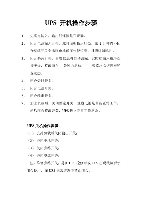
UPS 开机操作步骤
UPS 开机操作步骤
1、先确定输入、输出线连接是否正确。
2、闭合电源输入开关,此时面板指示灯亮,在1分钟内不闭
合整流开关会出现电池低压告警信息,且蜂鸣器鸣叫。
3、闭合整流开关,告警信息将自动消除,此时如输入相序连
接无误,整流器在1分钟内启动,并由旁路状态切换至逆变状态。
4、闭合旁路开关。
5、闭合电池开关。
6、闭合输出开关。
7、加上负载后,关闭整流开关,观察电池是否能正常工作,
然后闭合整流开关,UPS进入正常工作状态。
UPS关机操作步骤:
(1)去掉负载后关闭输出开关;
(2)关闭电池开关;
(3)关闭旁路开关;
(4)关闭整流开关;
注:维修旁路开关,是在UPS检修时或UPS出现故障后才闭合使用,在UPS正常逆态下禁止闭合。
UPS电源操作规程
UPS电源操作规程
UPS操作规程
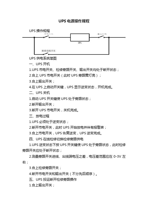
UPS供电系统简图
一、UPS开机
1.UPS市电开关、检修旁路开关、输出开关均处于断开状态;
2.合上UPS市电开关(此时UPS旁路黄灯亮);
3.合上输出开关;
4.在UPS上启动开关键,UPS显示逆变状态,开机完成。
二、UPS关机
1.启动UPS开关键使UPS处于旁路状态;
2.断开输出开关;
3.断开UPS市电开关,关机完成。
三、放电过程
1.UPS必须处于逆变状态;
2.断开市电开关,此时UPS开始放电并伴有报警声;
3.合上市电开关,UPS恢复逆变,UPS逆变完成。
四、UPS在线检修切换检修旁路供电
1.UPS逆变状态下按UPS开关键使UPS处于旁路状态,此时检修旁路开关应处于断开状态;
2.测量旁路开关进线、出线端电压之差,电压差范围应在0-3V左右;
3.合上检修旁路开关;
4.断开市电开关和输出开关(不分先后顺序)。
五、UPS投运断开检修旁路操作
1.合上输出开关;
2.合上输入开关;
3.断开检修旁路开关,并锁死检修旁路开关;
4.按UPS上开关键启动,UPS进入逆变状态。
六、UPS放电保养
UPS应每月放电1次(市电关闭),每季度对电池组进行深度放电保养。
注意:在UPS正常运行状态下禁止合上检修旁路开关!。
UPS操作手册

UPS操作手册UPS操作手册UPS操作手册目录UPS操作手册 (3)一、控制显示面板操作 (4)1.1控制显示面板 (4)1.2“历史记录”菜单下和当前记录窗中所有告警信息清单列表 (6)二、 UPS主机操作 (9)2.1 UPS主机开关按键 (9)2.2 UPS开机步骤(进入逆变供电模式) (11)2.3维修旁路操作步骤(如并机系统由两个以上单机并联组成,请勿使用内部维修旁路) (12)2.4 关断并分离运行中的并机系统的其中一台UPS (12)2.5 恢复并机系统中已隔离的单机 (12)2.6关机步骤(完全关闭UPS和负载) (13)2.7紧急停机(EPO)步骤 (13)2.8 UPS复位步骤 (13)三、注意事项 (14)一、控制(kòngzhì)显示面板操作1.1控制(kòngzhì)显示面板(miàn bǎn)操作控制显示(xiǎnshì)面板按功能可分为三个区域:摸拟(mō nǐ)电流图(LED指示灯),LCD显示和菜单键,控制按钮。
1)查看摸拟电流图(LED指示灯)的状态摸拟电流图区域提供六个指示灯,这些指示灯用于显示UPS的供电路径。
并且,各指示灯通过颜色(红、绿、黄)和状态(亮、灭、闪烁)指示UPS的当前运行和告警状态。
各指示灯的状态意义描述见表:2)检查(jiǎnchá)告警(gàojǐng)蜂鸣器摸拟(mō nǐ)电流图区域提供告警蜂鸣器。
UPS在运行过程中可伴随三种不同的声音(shēngyīn)告警。
3)参看LCD面板的数据操作控制显示面板上提供LCD显示屏和五个菜单键(F1,F2,F3,F4,HELP)。
可浏览UPS的输入、输出、负载和电池参数,及时获得UPS的当前状态和告警信息,并进行相关功能设置和控制操作。
LCD还可提供最多512条历史告警记录备用户查询,给故障诊断提供可靠依据。
LCD主显示屏划分为以下5个显示窗:系统信息窗、菜单窗、UPS数据窗、当前记录窗和键盘解释窗。
梅兰日兰UPS使用操作说明
梅兰日兰UPS使用操作说明一、操作面板显示和按键说明1.整流/充电器指示灯1)指示灯熄灭:整流/充电器停止运行2)指示灯常亮成绿色:整流/充电器运行正常3)指示灯常亮成红色:整流/充电器故障,表示以下的一种或几种故障;输入开关Q1断开,整流/充电器输入端的保护保险FUE熔断整流/充电器模块内部异常高温电池充电电流异常增大电池充电电压异常升高整流/充电器的控制电路板没有校验或没有设置参数,控制电源板故障2.电池指示灯1)指示灯熄灭:电池正在浮充电2)指示灯闪烁成绿色:电池正在强充电3)指示灯常亮成绿色:负载由电池供电4)指示灯闪烁成红色:电池低电压停机预报警5)指示灯常亮成红色:电池后背时间结束且电池断路器QF1断开,或电池故障;3.静态旁路指示灯1)指示灯熄灭:电源2在容限范围内,且静态旁路停止2)指示灯常亮成绿色:静态路旁导通工作3)指示灯常亮成红色:表示以下一种或几种故障:电源2的电压或频率超出容限范围静态旁路故障逆变器输出接触器K3N运行故障逆变器响应故障并联UPS静态旁路模块内部异常高温静态旁路通风故障静态旁路控制电路板的电源故障切换控制电路板故障逆变器控制电路板没有校验或没有设置参数控制电源板故障4.逆变器指示灯1)指示灯熄灭:逆变器停机2)指示灯闪烁成绿色:逆变器启动并运行,但还没有切换带负载3)指示灯常亮成绿色:逆变器运行正常4)指示灯常亮成红色:逆变器故障,表示以下一种或几种故障:由于逆变器输出电压超出容限范围而导致逆变器停机逆变器输出保护保险FUS熔断逆变器模块上的保护保险熔断并联UPS逆变器故障逆变器输出变压器内部异常高温逆变器模块内部异常高温输出电压故障幅值或相位并联UPS逆变器时钟故障逆变器控制电路板没有校验或没有设置参数控制电源板故障5.负载指示灯1)指示灯熄灭:负载端没有供电2)指示灯常亮绿色:负载由逆变器或电源2通过静态或维修旁路供电6.蜂鸣器在下列情况下蜂鸣器鸣响:负载由电源2供电负载由电池供电运行故障对小故障或在电池给负载供电时,蜂鸣器的音量较小,间隔长,当接收到“电池低电压停机预报警”后,鸣响声音增大,间隔缩短,最后如果逆变器停机,鸣声更大,且变成连续鸣声;按一下蜂鸣器清音键可以关闭鸣响;如果蜂鸣器关闭了,更高级的报警会引起它再次鸣响;7.紧急停机按键按下此键会使整个UPS停机逆变器和整流/充电器停止运行,电池断路器断开,封锁静态路旁,干借点11板上的继电器的动作;8.逆变器启动按键这个按键用来在机柜上启动逆变器,当按下此键时,绿色的“逆变器”指示灯4闪烁,表示已经接到了启动命令;当逆变器与电源2同步后,它就会给负载供电,绿色的“负载”指示灯5维持常亮,负载由UPS供电且系统功能正常,如果电源2不满足切换条件电源2的电压、频率或相位条件超限;逆变器不会启动,系统等待一个特殊的命令见“强迫切换”键20;9.逆变器停止键这个按键将逆变器停机;1)按住“逆变器停机”键9三秒钟2)如果电源2满足切换条件:负载无间断地切换到电源2逆变器停机绿色的“逆变器”指示灯4熄灭绿色的“静态旁路”指示灯3变成常亮3)如果电源2不满足切换条件,这个键失效;警告:如果进行强迫切换,负载的供电会有秒的间断; 10上翻页键11.下翻页键这两个键用来向前和向后翻动菜单12确认键这个键用来肯定回答显示器上提出的问题13功能键这个键用来实现几个功能,包括选择显示的语言中文或英文、显示器的对比度、蜂鸣器的音量、指示灯测试、日期和时间的设定、显示屏反白、事件登录等;14电压键这个键用来阅读各种电压测量值.1)电源1的线电压2)电源2的线电压和相电压3)负载的线电压和相电压15.电流键这个键用来阅读各种电流测量值1)电源1、2和负载的电流2)负载百分率3)负载的峰值因数16.功率/频率键这个键用来阅读其他的测量值1)电源1、2和负载的频率2)负载的视在功率和有功功率3)负载的功率因数4)逆变器的负载率17.报警指示灯这个指示灯指示现在设备有报警,按键18可以显示报警信息;18.报警键这个键用来显示当前的和存储的报警信息,并将蜂鸣器清音19.电池键这个键用来阅读有关电池的各种测量值1)电池电压或不带电池的频率变换器的直流电压2)电池电流充电电流或放电电流3)电池的温度4)电池的后备时间5)逆变器负载率20.强迫切换键当UPS运行在“节能”方式时,这个键用来人为地将负载切换到逆变器,或从逆变器切换到静态旁路返回切换;切换或返回切换只有在肯定的回答了系统显示屏上的请求后才能实现,并且显示屏上会警告用户负责供电可能有间断的危险;21.报警复位键这个键用来将存储的报警信息复位,但只要在报警已经清除后系统才能接受复位22.蜂鸣器复位键这个键用来停止鸣响,然后,新的报警会再次鸣响23.显示屏这个显示屏连续的显示系统运行状态二、UPS开关位置1.输入输出开关1输入开关:两台UPS输入开关在配电房1AT1配电柜内,断开两个开关后,UPS自动切换到电池供电;如图3)输出开关:两台UPS输出开关在配电房1AP1配电柜内,断开两个开关后,UPS供电的负载断电;4)电池开关:分别安装在UPS房两个电池架上,断开后将无法提供后备供电,当市电中断或UPS输出开关断开时,所供的负载断电;4UPS机房自带开关Q1:主路市电输入开关Q4S:旁路输入开关Q2BP:外置维修旁路开关Q5N:输出开关三、UPS使用操作单机系统1.供电正常情况下开机启动程序1)断开UPS主机上的所以开关和电池开关2)检查并闭合配电柜上的UPS输出开关3)闭合Q1开关,显示板A整流器指示灯亮4)闭合对应的蓄电池组总开关,显示板D电池指示灯亮5)闭合Q4S旁路输入开关,显示板C静态旁路指示灯亮6)闭合Q5N输出开关,负载指示灯,此时负载由旁路供电7)按绿色逆变器启动按钮约3秒,逆变器启动,显示板B逆变器指示灯变亮,负载由旁路切换到逆变器供电,启动完成2.关机程序1)按灰色逆变器停机按钮3秒,逆变器停机2)依次断开Q5N,Q4S,Q1,电池开关即可,UPS完全下电3.单机维修旁路切换1)按灰色逆变器停机按钮3秒,逆变器停机2)依次断开Q1开关,断开电池开关,闭合Q3BP开关,断开Q4S和Q5N开关,此时UPS处于维修旁路支状态并机系统1.供电正常情况下开机启动程序1)断开两台UPS主机上所有的开关和电池开关2)检查并闭合配电柜上的两台UPS输出开关3)闭合两台机组上的Q1开关,两台显示板1路灯亮4)闭合两台蓄电池组总开关,两台电池指示灯亮5)闭合两台机组上的Q4S旁路输入开关,两台显示板A整流器指示灯亮;6)分别按绿色逆变器启动按钮3秒,两台逆变器启动,显示板B逆变器指示灯变亮7)先后间隔闭合Q5N输出开关,两台机组负载指示灯亮,此时两台机组启动完成;2.关机程序1)断开其中一台机组是的Q5N开关,然后在机组上的灰色逆变器停机按钮3秒钟,逆变器停机2)依次断开Q4S,Q1,电池开关即可,此时该机组下电3)按照1和2步骤关闭另一台机组3.单机维修旁路切换1)按下两台UPS的灰色逆变器停机按钮2)断开两台机组的Q1,和电池开关3)分别闭合两台机组的Q3BP开关,再断开Q4S和Q5N4)两台机组处于维修旁路状态注意:在任意一台机组逆变器未关的情况下,严禁闭合Q3BP开关。
梅兰日兰UPS说明书
E-51028230XT/BG - 1User manualMGE™ Galaxy™ PW20 - 200 kVA2 - E-51028230XT/BGContents IntroductionGeneral characteristics of MGE™ Galaxy™ PW UPSs (5)System description (6)Different types of MGE™ Galaxy™ PW systems (7)Isolation and protection devices (7)Operation in on-line mode (8)Operation in "eco" mode (10)Operation with an engine generator set (11)Inverter shutdown or overload (12)Output voltage quality and continuity (12)Description of MGE™ Galaxy™ PW cubiclesUPS cubicle (13)Battery cubicle (14)Control panel General (14)Presentation (15)Start-upSystem start-up (17)Start-up of a module (18)ShutdownShutdown of the inverter (19)Shutdown of a rectifier/charger (19)Control-panel displayGeneral organisation (20)Display of messages (20)Measurement system (24)Voltage measurementsi (24)Current measurements (24)Power and frequency measurements (24)Battery measurements (25)Selections and settings (25)Alarms General (28)Maintenance bypass (28)Environment informationSignal reception (29)Signal transmission (29)Logging and time-stampingPresentation of event time-stamping by MGE™ Galaxy™ PW (30)Utilisation via the MGE™ Galaxy™ PW display (30)Utilisation via Teleservice (33)MaintenanceMaintenance configuration (34)Battery maintenance (37)Visual check (37)Functional check (37)Training center (38)OptionsIsolating and voltage matching transformer for the normal and bypass ACSource and the load (39)Harmonics filter and power factor improvement (39)Safety of life and property (39)Empty cubicles (40)Electrical supervision (40)E-51028230XT/BG - 3All products in the MGE™ Galaxy™ PW range are protected by patents. They implement original technology not available tocompetitors of APC by Schneider Electric.To take into account evolving standards and technology, equipment may be modified without notice. Indications concerningtechnical characteristics and dimensions are not binding unless confirmed by APC by Schneider Electric.This document may be copied only with the written consent of APC by Schneider Electric. Authorised copies must be marked"MGE™ Galaxy™ PW User Manual, N° 51028230XT".4 - E-51028230XT/BGIntroduction General characteristics of MGE™ Galaxy™ PW UPSs(1): As per standards ENV 50091-3 / IEC 62040-3.(2): The losses indicated are those produced at full rated load with the battery float charging. They must be taken into account when sizing the ventilation system.(3): Not including any built-in options, such as harmonic filters or a bypass AC-source isolation transformer.E-51028230XT/BG - 5System description(see figure 1)◗ a rectifier/charger module (A) converts 3-phase AC power from the normal AC source supply (1) into DC power for the normal inverter input and float charges or recharges the battery;◗ a battery unit (D) provides backup power for the inverter in the event of a voltage drop or a normal AC source failure;◗ an inverter module (B) converts the DC power supplied by the rectifier/ charger module or the battery unit into 3-phase AC power for the load;◗ a static bypass module (C) ensures the instantaneous transfer of the load to the bypass AC source input in the event of an inverter shutdown (initiated by the user or by a protective device) or a sudden overload;◗ a maintenance bypass isolates the UPS for maintenance and transfers the load to bypass AC source input without interrupting the supply of power. The maintenance bypass is made up of three manual switches (Q3BP, Q4S and Q5N).Note◗ the normal AC input and the bypass AC input have different functions and, depending on the installation, may be protected differently upstream and/or come from different sources.◗ frequency converters are available without backup batteries;◗ the static bypass line and the maintenance bypass line do not exist in installations where the load frequency and the bypass AC source frequency are different (for example in frequency converters);◗ when increased power is required, several MGE™ Galaxy™ PW units may be connected in parallel. In this configuration, an "isolation" function is added for the UPS system as a whole for maintenance purposes, without interrupting the supply of power to the load.Introduction (cont.)The system may also include :◗ an isolating transformer on bypassAC input;◗ a passive harmonic filter (FAH) onthe normal AC input;◗ an active harmonic conditioner on thenormal AC input;◗ different remote control, indicationand display systems.Schematic diagram of the MGE™ Galaxy™ PW systemFig. 16 - E-51028230XT/BGDifferent types of MGE™ Galaxy™ PW systems Frequency converter without battery backup powerParallel UPS systemFig. 2Single-UPS unitFig. 3Frequency converter with battery backup power Fig. 4See figure 5 showing two parallel-connected (redundant) UPS units.A static bypass (C) does not exist inconfigurations.When increased power is required (twoto four parallel units), an externalbypass must be added (see figure 6).Isolation and protectiondevices(See figure 1 on previous page):◗ Q1 (switch):isolation of the rectifier/charger (A)from the normal AC source (1);rectifier/charger (A) start-up;◗ QF1 (circuit breaker):battery (D) protection and isolation;◗ Q5N (switch):isolation of the UPS (B) from theload;◗ Q4S (switch):◗isolation of the static bypass (C) fromthe bypass AC source (2);◗ Q3BP (switch):bypass switch for maintenance;◗ FUE (fuses):protection of the rectifier/charger (A)from the normal AC source;◗ FUS (fuses):protection of the inverter (B) from theload.Note:◗ switch Q3BP does not exist onparallel UPS systems constituted toincrease available power;◗ the "Q3BP" and "Q4S" switches donot exist on frequency converters;◗ circuit breaker QF1 does not exist oninstallations without batteries.External bypass for parallelUPSs and the hot-swapoptionSee figure 6.◗ Q5N (switch): isolation of theinverters of all the parallel UPSsystems from the load;◗ Q4S (switch): isolation of the staticbypasses (C) on each parallel unitfrom the bypass AC source (2);◗ Q3BP (switch): bypass switch formaintenance.Fig. 6Fig. 5Introduction (cont.)E-51028230XT/BG - 78 - E-51028230XT/BGIntroduction (cont.)Operation in on-line modeNormal operationNormal AC source power is available (see figure 7).◗ lights 1 ,4 and 5 shine green on the control panel;◗ the power necessary for the load is provided by the normal AC source (1)through the rectifier/charger (A) and the inverter (B);◗ the rectifier/charger (A) also supplies the power to float charge and recharge the battery if any.The rectifier/charger output voltage (DC) is regulated to supply:the float-charging or the recharging voltage for vented lead-acid or Ni/Cd batteries,◗ a single charge voltage for sealed lead-acid batteries.The voltages depend on the number of battery cells and the batterymanufacturer. Factory set, they may also be adjusted by after-sales support technicians.An electronic board continuouslymeasures the battery temperature and automatically adjusts the voltages.Note:In parallel MGE™ Galaxy™ PWsystems, the power drawn by the load is equally shared between the differentunits.Operation with the normal AC source downSee figure 8.In the event of a normal AC source failure or voltage outside specifiedtolerances of ±10% in amplitude (±15%optionally), the rectifier/charger (A)stops and the battery (D) supplies the necessary backup power to the load via the inverter (B). The battery, float-connected between the rectifier/charger and the inverter, discharges during this operating mode.Lights 2 ,4 and 5 shine green.The user is warned of battery operation by the slow beeping of the buzzer 6(see figure 19) and the message "LOAD PROTECTED, BATTERY DISCHARGING", followed by theremaining backup time and the percent load.This information is also available via volt-free changeover contacts for remote control devices.Note:In the event of a normal AC source failure, frequency converters without a battery shut down and the load is nolonger supplied.Battery timeThe available battery time during a normal AC source outage depends on the:◗ rated capacity of the battery;◗ power consumed by the load;◗ temperature of the battery;◗ age of the battery.The specified battery time corresponds to a minimum duration at full rated load.The actual backup time can therefore be greater if the system operates below its full rated load during the normal AC source outage. Operation on battery power can be extended beyond the specified time by reducing the load power consumption (by disconnecting non-critical loads).A "low battery" warning signal is sent via volt-free changeover contacts for remote control devices when thebattery voltage reaches a level slightly above the minimum level. This signal warns the user of the imminent end of battery power. On the device itself, the buzzer beeps rapidly.The message "LOW-BATTERYSHUTDOWN WARNING" is displayed,followed by the remaining backup time and the percent load. Light 2 turns red and flashes.Battery power stops when the voltage supplied by the battery reaches the minimum threshold (335 V). This results in inverter shutdown andtransfer of the load without interruption to the bypass AC source. Light 2shines red (not flashing). The message "LOAD NOT PROTECTED, ON-LINE MODE" is displayed and the buzzer sounds continuously.If the bypass AC source also fails, the load is no longer supplied. The inverter automatically shuts down when the time on battery power exceeds three times the specified backup time.Note:The "low battery shutdown" warning signal can be sent with an adjustable time delay prior to the effective end of battery power.Fig. 7Fig. 8E-51028230XT/BG - 9Operation with the normal AC source restoredSee figure 9.When normal AC source power (1) is restored or its voltage returns to within specified tolerances, the system automatically returns to its normal operating mode described above (on the condition it did not reach the end of battery power). If the end of battery power was reached (with the resulting inverter shutdown), the rectifier/charger (A) restarts automatically, but theinverter (B) must be restarted manually.The rectifier/charger recharges the battery (D) which was dischargedduring the mains outage. During battery charging, light 2 flashes green.The message "BATTERY CHARGING"is displayed, together with the value of the recharging current and battery voltage.The battery charge cycle takes place in two steps (see figure 10):◗ step 1: the battery is recharged at a constant current limited to 0.1C10 (i.e.1/10th of the battery capacity specified for a 10 hour discharge). The DC voltage increases with the battery charge until the charge level is reached;◗ step 2: the battery is recharged at constant voltage equal to the charge level (maximum value 463 V).The charging current graduallydecreases until reaching a specified low value (floating current).For vented lead-acid batteries, the rectifier/charger supplies the charging voltage for 0 to 255 hours (parameter defined by the after-sales support department) and then the floatingvoltage. For sealed lead-acid batteries,the charging and floating voltages are the same.Note 1:If the normal AC source failure isshorter than 0 to 255 seconds (default value = 30 seconds) (parameter defined by after-sales supportdepartment), the charger automatically supplies the floating voltage given the low battery discharge.Note 2:In frequency converters without battery power, the return of normal AC source power results in the automatic restart of the rectifier/charger and the inverter.Fig. 9Fig. 10Battery charge cycleIntroduction (cont.)Introduction (cont.)Operation with bypass AC source restored◗ no battery discharge (see figure 11). When bypass AC source power supply (2) is restored or returns to within specified tolerances, the load is transferred back to the static bypass (C), without an interruption in the supply of power.Note: this operating mode does not depend on the status of the normal AC source, which may be within or outside the specified tolerances.◗ after battery discharge (see figure 12).Operation of the rectifier/charger (A) with the battery (D) is identical to that presented in the section on on-line mode operation above.Forced transfer and return transfer◗ forced transfer. When the load is supplied via the static bypass (C), it may be transferred to the inverter (B) by pressing pushbutton 20 (see figure 19 in the "control panel" section).The message "FORCED TRANSFER TO INVERTER REQUESTED, POWER TO LOAD MAY BE INTERRUPTED" is displayed. Confirmation by pressing pushbutton 12force transfer. The message "LOAD FORCED TO INVERTER, ECO MODE" is displayed. Whatever the status of the bypass AC source, a return to normal operation in "ECO" mode is possible only through a forced return transfer to the static bypass (C).◗ forced disconnection: as the load is supplied by the inverter (B), it can be transferred to the bypass AC source (M2) via the static bypass (C) by pressing the pushbutton 20 . The message "FORCED TRANSFER TOM2 REQUESTED, POWER TO LOAD MAY BE INTERRUPTED" is then displayed. Confirmation by pressing pushbutton 12disconnection.Note:There are two possibilities: the bypass AC source is within tolerances or outside tolerances. In the first case, the UPS in "ECO" mode returns to normal operation.In the second case, the transfer will take place with a power cut to the load if the bypass AC source is present, or the load will cease to be supplied if it is absent. In both cases, the display reads "LOAD NOT PROTECTED, ECO MODE".Caution:Return to normal operation of the installation in the "ECO" mode is possible only after the bypass AC source has returned to within specified tolerances.Operation in "ECO" modeNormal operationSee figure 11.The power required by the load is supplied by the bypass AC source (2), via the static bypass (C). The rectifier/ charger (A) supplies the power required to float charge and recharge the battery (D).Lights 1 , 3 and 5 shine green and light 4 flashes green. The message "LOAD PROTECTED, ECO MODE" is displayed.Operation with the bypass AC source outside tolerancesWhatever the status of the normal AC source, operation of the rectifier/ charger (A) with the battery (D) is identical to that presented in the section on on-line mode operation above. When bypass AC source (2) characteristics are outside tolerances (voltage: ±10%; frequency as per personalisation; phase sync with inverter ±3°), the load is supplied via the inverter (B).From then on, the minimum operating time on the inverter (B) is 2 minuteseven if the bypass AC source returns to within specified tolerances. Refer to figure 7 in the general appendix if the normal AC source is present, and to figure 8 if it is absent. After this 2 minute period, the load is immediately transferred to the bypass AC source when the latter returns to within specified tolerances.Note:The maximum transfer time of the load from the static bypass (C) to the inverter (B) is 15 ms.Fig. 12Fig. 1110 - E-51028230XT/BGParallel UPSs with redundancy◗ the shutdown of one UPS unit is ofno consequence for the load. Theothers each take up an equal amount of load power and the load continues to be supplied normally;Unit shutdown results in the following on the control panel:lights 4 and 5 go off,activation of the buzzer (continuous beep),the message "LOAD NOTPROTECTED, PARALLEL ON-LINE MODE" is displayed;◗ in the event of an overload, the system only loses its redundancy as long as the overload is less than the total rated power of the functioning units. If the overload is greater, the operating mode is that previously described for systems without redundancy.Frequency converters◗ in the event of a shutdown, the loadis no longer supplied with power;◗ in the event of a major transient overload (greater than 1.65 In), the inverter will current limit to 165% of their rated current for 1 second before stopping;◗ in the event of a smaller but prolonged overload, the inverterrespects the same overload curve as the single inverter and shuts down;◗ in all three of the above cases,inverter shutdown results in the following:lights 4 and 5 go off,◗ activation of the buzzer (continuous beep),the message "LOAD NOTPROTECTED, ON-LINE MODE" is displayed.Inverter shutdown or overloadSee figure 13 for devices orinstallations operating in on-line mode with a bypass AC source.If the conditions are not satisfied, the inverter will current limit to 165% of its rated current for 1 second before stopping;◗ in the event of a small but extended overload (i.e. a continuous level of power exceeding the full rated load),the inverter will continue to supply power for a period depending on the magnitude of the overload (10 minutes for a 125% overload, 1 minute for a 150% overload). See the overload curve in figure 14;◗ in all three of the above cases,inverter shutdown and supply of the load via the bypass AC source results in the following on the control panel: light 4 goes off,◗ activation of the buzzer (continuous beep),◗ light 3 shines green,◗ the message "LOAD NOTPROTECTED, ON-LINE MODE" is displayed.Parallel UPSs without redundancyThe shutdown of one inverter results in overload on the other inverters in operation. Two cases may then arise:◗ if the overload on each remaining inverter is > than 1.65 ln, the load is immediately transferred to the bypass AC source;◗ if the overload is less than 1.65 ln,the remaining inverters support the overload (see curve in figure 14), and the load is transferred to the bypass AC source;◗ after this transfer: the light 4 goes off,◗ the buzzer is activated and sounds continuously,◗ the light 3 goes on and turns green, the message "LOAD NOTPROTECTED, PARALLEL ON-LINE MODE" is displayed.Single-UPS unit (on-line or "ECO" mode)◗ in the event of a UPS shutdown(initiated by the user or by an internal protective device), the load isautomatically transferred to the bypass AC source. If transfer conditions are satisfied, transfer takes place instantly,without interruption to the load;Note: transfer conditions are not satisfied when bypass AC source characteristics are outside tolerances (voltage: ±10%; frequency as per personalisation; phase sync with inverter ±3°);◗ in the event of a major transient overload (greater than 1.65 In),immediate transfer takes place asabove, without interruption to the load.The return to the inverter is automatic when the overload disappears if the number of possible returns has not been reached (0 to 255, programmable by personalisation). If this number has been reached, the load continues to be supplied by the bypass AC source. This operating mode allows start-up of load devices causing high inrush currents.This system requires satisfied transfer conditions.Fig. 13Fig. 14Introduction (cont.)Operation with an engine generator setSee figure 15 below.If a stand-by generator is included in the installation, it is generally started automatically in the event of a normal AC source failure and connected to the main low voltage switchboard. It is disconnected when normal AC source power is restored.With such a system, the requiredbattery time may be reduced to the time necessary for starting and bringing on line the stand-by generator. The battery (D) supplies power to the inverter (B)during the transfers:◗ normal AC source to the generator;◗ generator to the normal AC source.The transfer sequences described above (normal AC source ➜ battery,battery ➜ generator, generator ➜battery, and battery ➜ normal ACsource) are fully automatic. They in no way affect the load and require no manual operation by the user.Note:To avoid load surges on the generator,the rectifier/charger is started with a 10second maximum current consumption walk-in (lasting 3 to 10 seconds,depending on the percent load).To avoid overloading an undersized engine generator set, it is possible to set a maximum power level drawn by the normal AC input. Any additional power required is supplied by thebattery. This modification can be made on site by an APC by Schneider Electric technician.Fig. 15Example of an installation with an engine generator setIntroduction (cont.)Output voltage quality and continuityThe output voltage is stable inamplitude and frequency and is free of interruptions or transients outside specified tolerances, irrespective of normal AC source or load disturbances (outages, load step changes, etc.).Steady state voltage regulationFor stable or slowly varying loadconditions, the inverter output voltage is regulated to within ±0.5% in amplitude.The frequency of the output voltage can theoretically be regulated to within 0.1% of the rated value, however the output frequency range may beintentionally extended to a maximum of ±2 Hz so that the inverter can remain synchronised with the bypass AC source and its inherent frequency fluctuations, thus enabling transfer of the load to the bypass line at any time.Note:The output frequency range can be personalised and if necessary modified on the customer site by a qualified APC by Schneider Electric supporttechnician from ±0.25 Hz to ±2 Hz in 0.25 HZ steps.When the bypass AC source voltage moves outside this frequency range,the inverter is desynchronised and operates in "free running" mode, with the output frequency regulated to a high level of accuracy by a quartz oscillator.When the bypass AC source frequency returns to within the specifiedtolerances, the inverter is gradually re-synchronised to the bypass line at a rate of 0.5 Hz to 2Hz/s (as per the value personalised by the after-sales support department), thus avoiding exposing the load to sudden frequency variations.Transient voltage regulationThe inverter output voltage is not notably affected by instantaneousmajor variations in load characteristics.This is made possible by the PWM (Pulse Width Modulation) chopping technique and the microprocessor-based regulation system that instantly compensates for any variation. In particular, the inverter output voltage remains within +/- 2% of the rated voltage for load step changes of 0 to 100% or of 100 to 0%.Description of MGE™ Galaxy™ PW cubiclesFig. 16Control panelBattery cubicleFigure 17 shows an example of component layout in a battery cubicle or a battery circuit-breaker enclosure. Legend for figure 17:1 - battery isolation and protection circuit breaker QF1,2 - battery cells.Fig. 17GeneralThe control panel onMGE™ Galaxy™ PW UPSs comprisesthe basic controls and indicationsrequired to check the general status ofthe system (see figure 19).Located in the upper right part of thecubicle front, the control panel isdesigned to provide an easy and rapidoverview of system status (see figure19 on next page).Interpretation of symbols is very simpleand requires no particular training.The information concerns only thecubicle on which the panel is located.The panel indicates:◗ normal operation (load protected);◗ operation with load on battery power;◗ abnormal situations (operatingproblem);◗ dangerous situations (load notprotected).Note:The information on the bypass ACsource provided below does notconcern frequency converters.Information on batteries does notconcern frequency converters withoutbatteries.Fig. 18"Inverter" light 4◗ light off: inverter OFF;◗ light flashing green: inverter starting,inverter ON but not connected to the load;◗ light shines green: normal inverter operation;◗ light shines red: inverter fault, the stored alarm indicates one or several of the following faults:◗ inverter shutdown due to inverter output voltage outside specified tolerances,protection fuse at the inverter output (FUS) blown,abnormally high inverter-output transformer temperature,abnormally high inverter temperature, output-voltage fault (amplitude or phase) (parallel UPSs),◗ fault, non-calibration or non-personalisation of the electronic control board for the inverter,fault on the electronic power-supply board."Load" light 5◗ light off: load not supplied;◗ light shines green: load supplied viathe inverter or the bypass AC source (via the static bypass).PresentationSee figure 19."Rectifier/charger" light 1◗ light off: rectifier/charger OFF;◗ light shines green: rectifier/chargerON;◗ light shines red: rectifier/charger fault,the stored alarm indicates one or several of the following faults:◗ input switch Q1 open,◗ protection fuse at the rectifier/charger input (FUE) blown,◗ abnormally high internal rectifier/charger temperature,abnormally high battery charge current,◗ abnormally high battery voltage,◗ fault, non-calibration or non-personalisation of the electronic control board for the rectifier/charger,fault on the electronic power-supply board."Battery light" 2◗ light off: battery float charging;◗ light flashing green: batteryrecharging;◗ light shines green: load on battery power;◗ light flashing red: low-battery shutdown warning;◗ light shines red: battery at end of backup time and circuit breaker QF1open, or battery fault."Static-bypass" light 3◗ light off: bypass AC source withinspecified tolerances and static bypass open;◗ light shines green: static bypass closed;◗ light shines red: the stored alarmindicates one or several of the following faults:◗ bypass AC source voltage orfrequency outside specified tolerances, static-bypass fault,◗ abnormally high internal static-bypass temperature,static-bypass ventilation fault, power-supply fault for the static-bypass control function,◗ fault on the electronic board controlling the transfer function,◗ non-calibration or non-personalisation of the electronic control board for the inverter,fault on the electronic power-supply board,fault on monitoring the "inverter ready" response channels (parallel UPS system).Buzzer 6The buzzer sounds in the following situations:◗ load supplied by the bypass AC source;◗ load on battery;◗ operating problems.It sounds slowly and discontinuously for a minor problem or when the inverter is on battery power.When the alarm "LOW BATTERY SHUTDOWN" is activated, the buzzer sounds more rapidly. Finally, if the inverter shuts down, the beep is loud and continuous. The buzzer may be reset by pressing a button. If the buzzer is reset, a higher level alarm will set it off again."Full-shutdown" button 7Pressing this button shuts down the entire UPS (shutdown of the inverter and rectifier/charger, opening of the battery circuit breaker and activation of a relay contact on the Media Contacts 11 board)."Inverter ON" button 8This button is used to start the inverter locally."Inverter OFF" button 9This button turns the inverter off locally.Fig. 19Control panel (cont.)。
UPS操作规程
UPS操作规程标题:UPS操作规程引言概述:UPS(不间断电源)是一种用于保护计算机、通信设备、医疗设备等重要设备免受电力波动和停电影响的设备。
正确的操作规程能够确保UPS的正常运行,延长设备寿命,保障设备安全运行。
本文将详细介绍UPS的操作规程。
一、UPS设备安装1.1 确认UPS设备的额定功率和输出电压,选择合适的安装位置。
1.2 将UPS设备固定在干燥通风的位置,避免受潮和高温影响。
1.3 将UPS设备与电源线、设备连接好,确保连接牢固可靠。
二、UPS设备开机操作2.1 首先检查UPS设备的电源线是否连接正确,电源开关是否处于关闭状态。
2.2 按照设备说明书操作,先打开UPS设备的电源开关,再打开连接设备的电源开关。
2.3 确认UPS设备正常工作,监测输出电压和电流是否稳定。
三、UPS设备日常维护3.1 定期检查UPS设备的电池状态,保证电池正常工作。
3.2 清洁UPS设备的散热孔和风扇,避免灰尘积累影响散热效果。
3.3 定期进行UPS设备的功能测试,确保设备正常运行。
四、UPS设备故障处理4.1 当UPS设备出现故障时,首先查看设备显示屏或指示灯,了解故障原因。
4.2 根据设备说明书或厂家建议,采取相应的故障处理措施。
4.3 如无法解决故障,及时联系专业维修人员进行维修。
五、UPS设备关机操作5.1 在停电或需要关闭UPS设备时,首先关闭连接设备的电源开关。
5.2 再关闭UPS设备的电源开关,待设备指示灯全部熄灭后,再拔掉电源线。
5.3 关闭UPS设备后,定期进行设备检查,确保设备安全可靠。
结语:正确的UPS操作规程能够确保设备正常运行,延长设备寿命,保障设备安全运行。
遵循以上操作规程,将有助于提高UPS设备的稳定性和可靠性,保障重要设备的正常运行。
梅兰日兰UPS操作步骤
梅兰日兰GALAXY 系列UPS 操作简介一、UPS 面板介绍梅兰GALAXY 系列UPS 面板显示和按键如下:➢ 在显示屏上可以看到UPS 运行的各种参数,按屏幕下方的按键可以查看相应的参数。
➢ 屏幕上方的指示灯代表各部件的工作状态,正常情况下各指示灯均应该为绿色或黄色,当指示为红色时,说明对应部件存在故障。
➢ 绿色按钮为启动逆变器按钮,当需启动逆变器时,按下该按键。
➢ 灰色按钮为停止逆变器按钮,当需要停止逆变器时,按下该按键3秒钟。
➢ 红色按钮为紧急停止按钮,一般不需触动。
UPS 开关位置如下图所示:紧急停机按钮 停止逆变器按钮 启动逆变器按钮Q1主路市电输入开关 Q4S 旁路输入开关 Q3BP 维修旁路开关Q5N 输出开关二、单机UPS操作(注意:克拉玛依局不属于单机UPS,请按三、四步骤操作)◆正常的单机UPS启动程序:1、保证所有开关都处于断开状态,电池输入开关也处于断开状态。
2、闭合Q1开关,此时市电送入UPS,显示面板1路左侧指示灯应被点亮;3、指示灯点亮后,闭合蓄电池空开,蓄电池指示灯应被点亮。
4、然后闭合Q4S旁路输入开关,显示面板2路指示灯应被点亮。
5、闭合Q5N输出开关,输出指示灯应被点亮,此时负载由旁路电源供电。
6、按绿色逆变器启动按钮,逆变器应启动,面板指示灯1路右侧灯应被点亮,此时UPS负载转由逆变器供电,启动过程完成。
◆单机UPS停机程序:◆按灰色逆变器停机按钮3秒钟,逆变器停机。
◆断开Q5N,Q4S,Q1,电池空开即可,UPS完全下电。
◆单机UPS维修旁路程序1、按灰色逆变器停机按钮3秒钟,逆变器停机。
2、依次断开Q1开关,断开电池开关,闭合Q3BP开关,断开Q4S和Q5N开关,此时UPS处于维修旁路状态。
三、主备用UPS操作(适用于克拉玛依20KV A UPS)◆正常的主备用UPS开机程序1、确认所有开关处于断开状态,包括电池开关;2、闭合备机Q1开关,待备机整流器灯(1路左侧)点亮后,闭合备机电池开关;3、闭合备机Q4S开关,旁路指示灯(2路)应点亮;4、闭合主机Q1开关,待主机整流器灯点亮后,闭合主机电池开关;5、闭合备机Q5N,闭合主机Q4S开关,主机旁路指示灯应点亮;6、闭合主机Q5N开关,输出指示灯应点亮;7、按下备机绿色逆变器启动按钮,等待逆变器指示灯亮(1路右侧);8、按下主机绿色逆变器启动按钮,等待逆变器指示灯亮;9、此时两台机组启动成功,负载由逆变器供电。
UPS操作
UPS开机顺序
1. 将插排插在立柱插座上,按插排通电按钮,使插排通电(插排红灯亮)。
2. 上推蓄电池组左侧开关。
3. 长按(2~3 S)UPS开关钮。
UPS工作状态:
正常通电时:UPS上侧指示灯从右向左开始亮绿灯,指示为UPS所接功率负载。
UPS下侧指示灯仅有两侧绿灯亮。
UPS无报警声。
断电时:UPS上侧指示灯全亮,指示为蓄电池组剩余电量,指示灯会随着使用时间的延长从右向左逐个熄灭。
UPS下侧指示灯左侧绿灯熄灭,下方黄灯亮,指示为蓄电
池组工作。
UPS有报警声。
正常关闭7500 fast机器后
UPS关机顺序:
1. 按UPS开关按钮。
2. 下推蓄电池组左侧开关。
3. 按插排通电按钮,使插排断电(插排红灯灭),将插排从立柱插座拔下。
- 1、下载文档前请自行甄别文档内容的完整性,平台不提供额外的编辑、内容补充、找答案等附加服务。
- 2、"仅部分预览"的文档,不可在线预览部分如存在完整性等问题,可反馈申请退款(可完整预览的文档不适用该条件!)。
- 3、如文档侵犯您的权益,请联系客服反馈,我们会尽快为您处理(人工客服工作时间:9:00-18:30)。
梅兰日兰U P S使用操作
说明
文稿归稿存档编号:[KKUY-KKIO69-OTM243-OLUI129-G00I-FDQS58-
梅兰日兰U P S使用操作说明
一、操作面板显示和按键说明
1.整流/充电器指示灯
1)指示灯熄灭:整流/充电器停止运行
2)指示灯常亮成绿色:整流/充电器运行正常
3)指示灯常亮成红色:整流/充电器故障,表示以下的一种或几种故障;
输入开关Q1断开,
整流/充电器输入端的保护保险(FUE)熔断
整流/充电器模块内部异常高温
电池充电电流异常增大
电池充电电压异常升高
整流/充电器的控制电路板没有校验或没有设置参数,
控制电源板故障
2.电池指示灯
1)指示灯熄灭:电池正在浮充电
2)指示灯闪烁成绿色:电池正在强充电
3)指示灯常亮成绿色:负载由电池供电
4)指示灯闪烁成红色:电池低电压停机预报警
5)指示灯常亮成红色:电池后背时间结束且电池断路器QF1断开,或电池故障。
3.静态旁路指示灯
1)指示灯熄灭:电源2在容限范围内,且静态旁路停止
2)指示灯常亮成绿色:静态路旁导通工作
3)指示灯常亮成红色:表示以下一种或几种故障:
电源2的电压或频率超出容限范围
静态旁路故障
逆变器输出接触器K3N运行故障
逆变器响应故障(并联UPS)
静态旁路模块内部异常高温
静态旁路通风故障
静态旁路控制电路板的电源故障
切换控制电路板故障
逆变器控制电路板没有校验或没有设置参数
控制电源板故障
4.逆变器指示灯
1)指示灯熄灭:逆变器停机
2)指示灯闪烁成绿色:逆变器启动并运行,但还没有切换带负载3)指示灯常亮成绿色:逆变器运行正常
4)指示灯常亮成红色:逆变器故障,表示以下一种或几种故障:由于逆变器输出电压超出容限范围而导致逆变器停机逆变器输出保护保险(FUS)熔断
逆变器模块上的保护保险熔断(并联UPS)
逆变器故障
逆变器输出变压器内部异常高温
逆变器模块内部异常高温
输出电压故障(幅值或相位(并联UPS)
逆变器时钟故障
逆变器控制电路板没有校验或没有设置参数
控制电源板故障
5.负载指示灯
1)指示灯熄灭:负载端没有供电
2)指示灯常亮绿色:负载由逆变器或电源2(通过静态或维修旁路)供电
6.蜂鸣器
在下列情况下蜂鸣器鸣响:
负载由电源2供电
负载由电池供电
运行故障
对小故障或在电池给负载供电时,蜂鸣器的音量较小,间隔长,当接收到“电池低电压停机预报警”后,鸣响声音增大,间隔缩短,最后如果逆变器停机,鸣声更大,且变成连续鸣声。
按一下蜂鸣器清音键可以关闭鸣响。
如果蜂鸣器关闭了,更高级的报警会引起它再次鸣响。
7.紧急停机按键
按下此键会使整个UPS停机(逆变器和整流/充电器停止运行,电池断路器断开,封锁静态路旁,干借点11板上的继电器的动作)。
8.逆变器启动按键
这个按键用来在机柜上启动逆变器,当按下此键时,绿色的“逆变器”指示灯(4)闪烁,表示已经接到了启动命令。
当逆变器与电源2同步后,它就会给负载供电,绿色的“负载”指示灯(5)维持常亮,负载由UPS供电且系统功能正常,如果电源2不满足切
换条件(电源2的电压、频率或相位条件超限)。
逆变器不会启动,系统等待一个特殊的命令(见“强迫切换”键20)。
9.逆变器停止键
这个按键将逆变器停机。
1)按住“逆变器停机”键(9)三秒钟
2)如果电源2满足切换条件:
负载无间断地切换到电源2
逆变器停机
绿色的“逆变器”指示灯(4)熄灭
绿色的“静态旁路”指示灯(3)变成常亮
3)如果电源2不满足切换条件,这个键失效。
警告:如果进行强迫切换,负载的供电会有0.8秒的间断。
10上翻页键
11.下翻页键
这两个键用来向前和向后翻动菜单
12确认键
这个键用来肯定回答显示器上提出的问题
13功能键
这个键用来实现几个功能,包括选择显示的语言(中文或英文)、显示器的对比度、蜂鸣器的音量、指示灯测试、日期和时间的设定、显示屏反白、事件登录等。
14电压键
这个键用来阅读各种电压测量值.
1)电源1的线电压
2)电源2的线电压和相电压
3)负载的线电压和相电压
15.电流键
这个键用来阅读各种电流测量值
1)电源1、2和负载的电流
2)负载百分率
3)负载的峰值因数
16.功率/频率键
这个键用来阅读其他的测量值
1)电源1、2和负载的频率
2)负载的视在功率和有功功率
3)负载的功率因数
4)逆变器的负载率
17.报警指示灯
这个指示灯指示现在设备有报警,按键(18)可以显示报警信息。
18.报警键
这个键用来显示当前的和存储的报警信息,并将蜂鸣器清音
19.电池键
这个键用来阅读有关电池的各种测量值
1)电池电压(或不带电池的频率变换器的直流电压)
2)电池电流(充电电流或放电电流)
3)电池的温度
4)电池的后备时间
5)逆变器负载率
20.强迫切换键
当UPS运行在“节能”方式时,这个键用来人为地将负载切换到逆变器,或从逆变器切换到静态旁路(返回切换)。
切换或返回切换只有在肯定的回答了系统显示屏上的请求后才能实现,并且显示屏上会警告用户负责供电可能有间断的危险。
21.报警复位键
这个键用来将存储的报警信息复位,但只要在报警已经清除后系统才能接受复位
22.蜂鸣器复位键
这个键用来停止鸣响,然后,新的报警会再次鸣响
23.显示屏
这个显示屏连续的显示系统运行状态
二、UPS开关位置
1.输入输出开关
1)输入开关:两台UPS输入开关在配电房1AT1配电柜内,断开两个开关后,UPS自动切换到电池供电。
如图
3)输出开关:两台UPS输出开关在配电房1AP1配电柜内,断开两个开关后,UPS供电的负载断电。
4)电池开关:分别安装在UPS房两个电池架上,断开后将无法提供后备供电,当市电中断或UPS输出开关断开时,所供的负载断电。
4)UPS机房自带开关
Q1:主路市电输入开关
Q4S:旁路输入开关
Q2BP:外置维修旁路开关
Q5N:输出开关
三、UPS使用操作
单机系统
1.供电正常情况下开机启动程序
1)断开UPS主机上的所以开关和电池开关
2)检查并闭合配电柜上的UPS输出开关
3)闭合Q1开关,显示板A整流器指示灯亮
4)闭合对应的蓄电池组总开关,显示板D电池指示灯亮
5)闭合Q4S旁路输入开关,显示板C静态旁路指示灯亮
6)闭合Q5N输出开关,负载指示灯,此时负载由旁路供电
7)按绿色逆变器启动按钮约3秒,逆变器启动,显示板B逆变器指示灯变亮,负载由旁路切换到逆变器供电,启动完成
2.关机程序
1)按灰色逆变器停机按钮3秒,逆变器停机
2)依次断开Q5N,Q4S,Q1,电池开关即可,UPS完全下电
3.单机维修旁路切换
1)按灰色逆变器停机按钮3秒,逆变器停机
2)依次断开Q1开关,断开电池开关,闭合Q3BP开关,断开Q4S和Q5N开关,此时UPS 处于维修旁路支状态
并机系统
1.供电正常情况下开机启动程序
1)断开两台UPS主机上所有的开关和电池开关
2)检查并闭合配电柜上的两台UPS输出开关
3)闭合两台机组上的Q1开关,两台显示板1路灯亮
4)闭合两台蓄电池组总开关,两台电池指示灯亮
5)闭合两台机组上的Q4S旁路输入开关,两台显示板A整流器指示灯亮。
6)分别按绿色逆变器启动按钮3秒,两台逆变器启动,显示板B逆变器指示灯变亮
7)先后间隔闭合Q5N输出开关,两台机组负载指示灯亮,此时两台机组启动完成。
2.关机程序
1)断开其中一台机组是的Q5N开关,然后在机组上的灰色逆变器停机按钮3秒钟,逆变器停机
2)依次断开Q4S,Q1,电池开关即可,此时该机组下电
3)按照1)和2)步骤关闭另一台机组
3.单机维修旁路切换
1)按下两台UPS的灰色逆变器停机按钮
2)断开两台机组的Q1,和电池开关
3)分别闭合两台机组的Q3BP开关,再断开Q4S和Q5N
4)两台机组处于维修旁路状态
注意:在任意一台机组逆变器未关的情况下,严禁闭合Q3BP开关。