WisWin数字标牌管理系统用户手册V2.1
WinWew软件说明书

第二章 软件安装与卸载 ........................................................................................................ 7
§2.1 软件的安装 ...................................................................................................................................... 7 §2.2 软件的卸载 ...................................................................................................................................... 7 §2.3 文件及文件夹................................................................................................................................. 7 §2.4 PCI 测控卡驱动程序的安装 ................................................................................................. 8
新WIS系统更新说明

新WIS系统更新说明1、信息采集-变更录入:变更报告单和不明情况报告单录入和修改页面加入了备注字段,可以在变更录入时加入特殊情况说明或备注说明。
2、信息采集-信息修改:增加删除基础信息卡的功能,在信息修改页面上增加,如果在报告期内建卡的,可以直接删除,如果是报告期以前建卡的需要向县级提交删除建卡申请,县级审批通过后直接将卡删除。
3、增加生育及家庭子女的删除审核功能(上报日期不为空),如果在报告期内上报的生育信息,可以直接删除,如果在报告期以前上报的生育信息需要向县级提交删除申请,县级审批通过后直接将生育删除。
4、修改的敏感字段需要审核,在县级审核前可以撤销申请。
5、操作人员难免会勿删除数据,从新上报后上报日期又不对,所以增加可以从删除日志中恢复被删除的数据。
如果再次恢复会提示已恢复,不会造成重复数据。
6、原程序中查询汇总---分类查询---违法生育信息---只显示夫妇姓名、女方出生时间、政策外孩次、违法原因、上报日期和管理单位,而违法生育时间和性别则不显示,目前增加了违法生育时间和性别的显示7、在随机查询→生育计划表的查询中,以前没有区分证件类型,现在已经加入。
8、查询汇总——分类查询(时期)。
如查询某一时期的所有措施不方便。
一级选单:手术信息,二级选单:缺少“全体”,现在已全部加入。
9、修改页面框架模式,采用较为简单的单页面实现方式,从根本上解决显示不全、无滚动条、弹出窗口消失等问题。
(在web.config中设定参数,可以设定是否启用选项卡,参数名为xxkbz)10、实现录入界面的限制和关联。
在录入界面上根据用户的输入将不允许录入的输入框设为不可用,或者根据之前的输入自动设定后续输入的默认值,或者根据用户的输入位置自动提取相应的内容。
例如如果出生的政策属性为外,政策外处罚原因就不用设定(在变更录入和基础信息卡采集页面中)11、采用水晶报表设计要打印的报表。
汇总报表的打印使用IE浏览器的打印功能,输出字体格式不确定,较难进行页面设置。
SWTMS终端网管系统使用手册-Sunniwell

SWTMS终端网管系统使用手册V3.1目录目录1.登录模块 (5)1.1用户管理 (5)1.2忘记密码 (7)2.设备管理 (8)1.3设备管理 (9)2.1.1删除 (9)2.1.2导出列表 (10)2.1.3刷新列表 (11)2.1.4实时扫描 (11)2.1.5定时扫描 (12)2.1.6终端日志收集 (12)2.1.7状态监控 (16)2.1.8IP Ping (17)2.1.9Trace Route (18)2.1.10写参数 (20)2.1.11读参数 (32)2.1.12升级 (34)2.1.13电源控制 (36)2.1.14恢复出厂 (38)2.1.15推送消息 (38)2.1.16远程协助 (39)1.4设备分组 (47)2.2.1手动分组 (47)2.2.2自动分组 (49)1.5参数模板 (52)2.3.1参数模板简介 (52)3.任务管理 (54)4.文件管理 (56)4.1上传版本文件 (56)4.2制作Linux补丁 (57)4.3制作Android补丁 (58)4.4制作Apk (59)4.5修改 (59)4.6删除 (60)5.数据统计 (61)6.系统管理 (62)6.1权限分类管理 (62)6.2操作日志 (63)6.3授权管理 (64)1.登录模块2.1用户管理a.在浏览器地址栏输入网管地址回车b.在首次登录网管时,先检查授权文件,若你已经成功授权则直接跳转登录界面,否则需要授权,如下所示按照授权界面描述,填写联系人、电话、公司名称发送邮件至swtms_license@申请授权文件c.依次输入用户名和密码,点击登录,如图1-1所示图1-1●初始用户名:admin 口令:Admin@123●语言选择:提供简体中文简体、英文选项,点击即可 ●修改错误密码锁定次数和锁定时间在/ROOT/WEB-INF/class/config.propertises 配置文件中修改为错误锁定次数(默认为3次)为锁定时间(默认为5分钟)d . 对于网管新增的操作员(详见系统管理操作员管理),首次登录需要设置密保,如图1-2 、 1-3所示说明图1-2图1-32.2忘记密码在登录界面点击忘记密码,出现图1-4界面;下一步后出现图1-5、图1-6、图1-7结束图1-4图1-5图1-6图1-72.设备管理设备管理模块有以下四部分组成:1.设备管理2. 设备分组3.参数模版2.1设备管理设备管理主要有删除、导出列表、刷新列表、实时扫描、定时扫描、终端日志搜集、状态监控、IP Ping、Trace Route、写参数、读参数、升级、重启/关机、恢复出厂、推送消息,显示/隐藏应用,如图2-1所示图2-12.1.1删除可在终端网管上删除该设备,便于用户管理终端,自由控制勾选需要删除的设备,点击“删除”即可2.1.2导出列表点击“导出列表”按钮,出现“导出全部”和“导出查询结果”,如图2-2所示图2-2选择“导出全部”,将会把当前显示的所有设备的信息,全部导出为一个devices .xlsx文件,如图2-3;图2-3选择“导出查询结果”,则会导出筛选后所显示的设备信息,如图2-4图2-42.1.3刷新列表刷新列表按钮可对页面进行刷新,更新设备信息和管理列表2.1.4实时扫描实时扫描是为了扫描未主动注册网管的设备,输入想要扫描的IP地址段,点击“扫描”等待出现结果后,勾选要添加的设备,点击“添加”。
WIZ200WEB 用户手册说明书
Document History InformationRevision Data DescriptionVer. 1.0 2008. 12. Release with WIZ200WEB launching23WIZnet’s Online Technical SupportIf you have any questions or want more information about WIZnet products, submit your question to the Q&A Board on the WIZnet website.(www.wiznet.co.kr) A WIZnet engineer will have an answer for you as soon as possible.4Table of Contents1. Introduction ......................................................................................................................................... 7 1.1. Main Function .........................................................................................................................................................7 1.2. Specification ............................................................................................................................................................8 1.3.Contents (WIZ200WEB-EVB) (8)2. Block Diagram ..................................................................................................................................... 93. WIZ200WEB Base Board .................................................................................................................. 114. Getting Started .................................................................................................................................. 16 4.1.Configuration Tool (16)4.1.1. Basic Configuration .................................................................................................................................. 16 4.1.2. Firmware Upload ....................................................................................................................................... 17 4.1.3. Webpage Upload ...................................................................................................................................... 19 4.1.4. Use of Rom File Maker rev3.0 .. (20)4.2.Operation Test (22)4.2.1. Hardware Interface ................................................................................................................................... 22 4.2.2.Testing the Function of Web Server (23)5. Programmer’s Guide ........................................................................................................................ 26 5.1. Memory Map ....................................................................................................................................................... 26 5.2. WIZ200WEB Firmware ................................................................................................................................... 26 5.3. Compile .................................................................................................................................................................. 28 5.4.Downloading (28)6. WIZ200WEB Hardware Specification ............................................................................................ 31 6.1. Parameters ............................................................................................................................................................ 31 6.2. Specification ......................................................................................................................................................... 31 6.3.Board Dimensions and Pin Assignment (31)6.3.1. Pin Assignment .......................................................................................................................................... 31 6.3.2. Size .................................................................................................................................................................. 32 6.3.3.Connector Specification (33)7. Warranty (35)5TablesTable 1. WIZ200WEB Specification .................................................................................................................8 Table 2. Contents of WIZ200WEB ...................................................................................................................9 Table 3. WIZ200WEB PIN MAP ..................................................................................................................... 12 Table 4. Expansion Connector ....................................................................................................................... 15 Table 5. WIZ200WEB Testing Environment .............................................................................................. 22 Table 6. WIZ200WEB Main Source .............................................................................................................. 27 Table 7. WIZ200WEB PINMAP .. (31)6FiguresFigure 1. Block Diagram .................................................................................................................................. 10 Figure 2. WIZ200WEB Base Board Layout ............................................................................................... 11 Figure 3. AVR JTAG Connector...................................................................................................................... 12 Figure 4. AVR ISP Connector ......................................................................................................................... 12 Figure 5. WIZ200WEB PIN MAP ................................................................................................................... 12 Figure 6. WIZ200WEB LED .............................................................................................................................. 13 Figure 7. WIZ200WEB Switch ........................................................................................................................ 13 Figure 8. WIZ200WEB 16x2 LCD .................................................................................................................. 14 Figure 9. WIZ200WEB VR ................................................................................................................................ 14 Figure 10. WIZ200WEB T emperature Sensor .......................................................................................... 15 Figure 11. Configuration T ool ....................................................................................................................... 16 Figure 12. Board Search Window ................................................................................................................ 18 Figure 13. Open dialog box for uploading ............................................................................................. 19 Figure 14. Firmware uploading window ................................................................................................... 19 Figure 15. Complete Uploading ................................................................................................................... 19 Figure 16. Flash Rom Image File .................................................................................................................. 20 Figure 17. ROM File Maker ............................................................................................................................ 21 Figure 18. ROM Image File Make ................................................................................................................ 21 Figure 19. WIZ200WEB External Interface ................................................................................................ 22 Figure 20. WIZ200WEB index page ............................................................................................................ 23 Figure 21. WIZ200WEB Digital Output Page .......................................................................................... 24 Figure 22. WIZ200WEB Digital Input Page .............................................................................................. 24 Figure 23. WIZ200WEB Analog Input Page ............................................................................................. 25 Figure 24. WIZ200WEB Memory Map ....................................................................................................... 26 Figure 25. AVR Studio ...................................................................................................................................... 28 Figure 26. ATmega128 ISP .............................................................................................................................. 29 Figure 27. WIZ200WEB Boot Loader Program ....................................................................................... 30 Figure 28. WIZ200WEB Pin Map .................................................................................................................. 31 Figure 29. WIZ200WEB Module Dimension ............................................................................................ 32 Figure 30. WIZ200WEB Base Board Size................................................................................................... 33 Figure 31. RJ-45 PIN Assignment ................................................................................................................ 33 Figure 32. RJ-45 PIN Assignment ................................................................................................................ 34 Figure 34. RS-232 PIN Assignment . (34)71. IntroductionWIZ200WEB provides the tiny embedded web server operating on low-speed MCU. It controls digital output or monitors digital and analogue input through web browser. The webpage is stored in the serial flash memory of the board, and can be updated through network.1.1. Main FunctionOperates as HTTP ServerGuarantee system stability and reliability by using W5300, the hardwired chip Provides Configuration Tool Program for easy control and confiuration Supports 10/100 Mbps Ethernet RoHS Compliant81.2. SpecificationITEMDescriptionMCUATmega128(having internal 128K Flash, 4K SRAM, 4K EEPROM, external 32K SRAM, 512K Serial Flash)ProtocolsTCP/IP - W5300 (Ethernet MAC & PHY Embedded)UDP – Configuration HTTP Server DHCPNetwork Interface 10/100 Mbps Auto-sensing, RJ-45 Connector Input Voltage DC 5V Power ConsumptionUnder 180mATemperature 0°C ~ 80°C (Operation), -40°C ~ 85°C (Storage) Humidity10 ~ 90%Table 1. WIZ200WEB Specification1.3. Contents (WIZ200WEB-EVB)WIZ200WEB ModuleWIZ200WEB Base Board9CD (Configuration Tool Program, Firmware, Manual areincluded)LAN Cable5V Power AdaptorTable 2. Contents of WIZ200WEB☞ If any missing item is found, contact to the shop you purchased.2. Block Diagram10Figure 1. Block DiagramThe main MCU of WIZ200WEB is 8 bit AVR (ATmega128). The Ethernet is processed by W5300, the hardwired TCP/IP chip. When connected to the IP address of the board at the web browser, the webpage in the serial flash memory is transmitted and displayed. Each webpage enables controlof digital input & output, analogue input and network configuration on the web.3. WIZ200WEB Base BoardWIZ200WEB module can be tested by using base board.11Figure 2. WIZ200WEB Base Board Layout①PowerThe power can be controlled by using power switch after connecting the DC 5V (500mA)adaptor.②ATmega128 JTAG ConnectorFigure 3. AVR JTAG Connector12③ATmega128 ISP ConnectorFigure 4. AVR ISP Connector④WIZ200WEB Module ConnectorThe connector has below pin map.Figure 5. WIZ200WEB PIN MAPJ3 J23.3V 3.3V ADC0/PF0 ADC1/PF1GND GND ADC2/PF2 ADC3/PF3SCL/INT0/PD0 SDA/INT0/PD1 ADC4/PF4 ADC5/PF5RXD1/INT2/PD2 TXD1/INT3/PD3ADC6/PF6 ADC7/PF7ICP1/PD4 XCK1/PD5 AREF PB4T1/PD6 T2/PD7 PB5 PB6SS/PB0 SCK/PB1 PB7 PE7MOSI/PB2 MISO/PB3 PE5 PE6RXD0/PE0 TXD0/PE1 PE3 PE4GND GND /RESET PE2Table 3. WIZ200WEB PIN MAP13⑤ Serial Connector(UART0)The debugging information is transmitted through Serial connector when proceeding development.⑥ Serial Connector(UART1)The debugging information is transmitted through Serial connector when proceeding development. ⑦ LED4 LEDs are installed in the WebServer Base Board, and connected to PORTB.4~7. .Figure 6. WIZ200WEB Base Board LED⑧ System Reset Switch⑨ SwitchSwitch is connected to PORTE.5~6. It is the slide switch.Figure 7. WIZ200WEB Base Board Switch⑩ 16X2 character LCD16x2 LCD is controlled with the method of 4 bit control It is connected to PORTD andPORTE.14Figure 8. WIZ200WEB Base Board 16x2 LCD⑪Variable ResistorIn order to test the analog data easily, you can use variable resistor and get the input valueof analog variable. Variable resistor is connected to ADC0 channel.Figure 9. WIZ200WEB Base Board VR⑫Digital Temperature SensorMicrochip’s TC77 having 12bit resolutions is used for temperature sensor. Temperaturesensor can be controlled by SPI and selected through PB0.Figure 10. WIZ200WEB Base Board Temperature Sensor15⑬Extension ConnectorIt is the connector (J12) to extend to GPIO and the function pins of ATmega128NO FUNCTION NO FUNCTION1 NC2 5V3 NC4 GND5 SCL/INT0/PD06 ADC0/PF07 SDA/INT0/PD1 8 ADC1/PF19 RXD1/INT2/PD2 10 ADC2/PF211 TXD1/INT3/PD3 12 ADC3/PF313 ICP1/PD4 14 ADC4/PF415 XCK1/PD5 16 ADC5/PF517 T1/PD6 18 ADC6/PF619 T2/PD7 20 ADC7/PF721 SS/PB0 22 AREF23 SCK/PB1 24 PE725 MOSI/PB2 26 PB627 MISO/PB3 28 PE529 PB4 30 PE431 PB5 32 PE333 PB6 34 PE235 PB7 36 /RESET37 PE1/TXD0 38 NC39 PE0/RXD0 40 NCTable 4. Expansion Connector4. Getting Started4.1.Configuration Tool4.1.1.Basic Configuration16Figure 11. Configuration T oolⓐVersion : It displays Firmware version.ⓑ Board List : If “Search” button is clicked, all MAC address of WIZ200WEB modules are displayed in the Board List.ⓒLocal IP/Port : IP Address of WIZ200WEBⓓSubnet : Subnet Mask of WIZ200WEBⓔGateway : Gateway Address of WIZ200WEBⓕ Web Page Upload : It is possible to upload ROM Image file to the internal flash memory ofWIZ200WEB. For the detail, refer to “4.1.3. Webpage Upload”.ⓖEnable DHCP Mode : It is the option for DHCP mode. Select a MAC Address to be used for17‘Enable DHCP mode’ at the ‘board list’. If you click “Setting” button, the board acquires IP and Subnet Mask by using DHCP . (By acquiring IP address from DHCP server, it can take some time) After acquiring network information from DHCP , re-booting is processed. If you click “Search” button again, you can check changed values. If you click MAC Address on the ‘Board list’, IP Address, Subnet Mask and Gateway information are displayed. If network information is not acquired due to any problem, IP , Subnet and Gateway Address are initialized to 0.0.0.0.ⓗ Search : “Search” function is used for searching module on the same LAN. If all the modules on the same subnet are searched by using UDP broadcast, their MAC addresses are displayed on the “Board List”.ⓘ SettingThis function is used for changing the configuration values of WIZ200WEB. After changing any configuration value, “Setting” button should be clicked for applying the value. With this, the values can be saved in the EEPROM and maintained even after shutting down the power of module. The process is as below.① Select a MAC address at the “Board list”. The configuration values of selected module aredisplayed in each field. ② Change the value of each field.③ If you click “Setting” button, the configuration is completed.④ The module is initialized with the changed configuration. (automatically re-booted) ⑤ In order to check changed value, search the module with “Search” button.ⓙ UploadFirmware is uploaded through network.Firmware upload process is described in detail at the “4.1.2 Firmware Upload” ☞ The initialization takes about 20~30 seconds after uploading the firmware.ⓚ Exit : It closes Configuration tool program.4.1.2. Firmware Upload① Execute Configuration Tool program and click ‘Search’ button.② If the module is correctly connected to the network, its MAC address is displayed on the ‘Board list’.18Figure 12. Board Search Window③Select a module at the ‘Board list’ and click ‘Upload’ button.☞ Before uploading through Ethernet, the network information should be set for correct network communication. By using PING test, it is possible to check if the value is appropriate for network communication.④As below dialog box is shown, select the Binary file and click ‘OPEN’ button.19Figure 13. Open dialog box for uploading☞ Be sure to use the firmware only for WIZ200WEB.⑤You can see below status window showing ‘Processing’.Figure 14. Firmware uploading window⑥If the file is uploaded, ‘Complete Uploading’ message is displayed.Figure 15. Complete Uploading4.1.3.Webpage Upload①Execute Configuration Tool program and click ‘Search’ button.②If the module is correctly connected to the network, its MAC address is displayed on the20‘Board list’.③ Select the board at the ‘Board list’ and click ‘web page Upload’ button.☞ Before uploading through Ethernet, the network information should be set for correct network communication. By using PING test, it is possible to check if the value is appropriate for network communication.④ As below dialog box shows, select the Flash Rom File System (*.rom) file and click ‘OPEN’ button.Figure 16. Flash Rom Image File☞ The Flash Rom File System should be created by using “Rom File Maker Tool rev3.0”. For the detail, refer to “4.1.4. Use of Rom File Maker rev3.0”⑤ If the file is uploaded, ‘Complete Uploading’ message is displayed.4.1.4. Use of Rom File Maker rev3.0Rom File Maker rev3.0 is the tool for creating ROM Image which enables the webpage to be stored in the Flash memory.Select the webpage by using ‘Add Files’ button.☞ There is limitation of file number in selecting at a time. (Normally, max 15 files can be selected simultaneously). If there are more files, use “Add Files” button for the several times.21Figure 17. ROM File MakerSelect ‘Rom Image File’ option. If you click ‘Make Image’ button, ‘*.rom’ file can be created.Figure 18. ROM Image File Make224.2. Operation TestIn this chapter, we will show how WIZ200WEB operates through a sample testing. The hardware and software requirements for testing are as below.PCWIZ200WEBHardware1) LAN Port1) WIZ200WEB Board 2) LAN Cable3) DC5V Power AdaptorSoftware1) Configuration Tool Program 2) Web BrowserTable 5. WIZ200WEB Testing Environment4.2.1. Hardware InterfaceFigure 19. WIZ200WEB External InterfaceHardware installation process is as below.STEP 1: By using RJ45 Ethernet cable, connect the board to the network.Serial CableLAN CablePower23STEP 2: Connect 5V DC adaptor to WIZ200WEB board.4.2.2. Testing the Function of Web ServerSTEP1: Supply the power to WIZ200WEB board.STEP2: Configure the board by using Configuration Tool.STEP3: Execute the web browser and input the IP address of the WIZ200WEB to access the webpage.STEP4: If connection is appropriately processed, ‘index.html’ page is displayed on the web browser.Figure 20. WIZ200WEB index pageSTEP5: Click ‘Digital Ouput’ menu at the web browser, and control the LED and LCD installed on the WIZ200WEB Base Board.24Figure 21. WIZ200WEB Digital Output PageSTEP6: Click ‘Digital Input’ menu, and check the status of switch installed on the WIZ200WEB Base Board. Switch status is updated every one second.Figure 22. WIZ200WEB Digital Input PageSTEP7: Click ‘Analog Input’ menu and check the voltage level according to Variable Resistor(VR) which is installed on the WIZ200WEB Base Board. The VR is updated every second.25Figure 23. WIZ200WEB Analog Input PageSTEP8: Click “ T emperature Read” menu and check current temperature by using the temperature sensor, TC77 installed on the WIZ200WEB Base Board.265. Programmer’s Guide5.1. Memory MapThe memory map of WIZ200WEB is composed of 128Kbyte code memory and 64Kbyte data memory. The data memory is composed of internal SRAM and W5300. In addition, 4Kbyte EEPROM is built in AVR. Environment variables of the board are saved in this EEPROM.Below figure shows the system memory map of the test board.Figure 24. WIZ200WEB Memory Map5.2. WIZ200WEB FirmwareThe firmware performs ProcessWebServer, ProcessDhcp and ProcessConfig in the main() Function ProcessWebServer() operates as webserver. It processes HTTP protocol from web browser, reads the web page in the Flash memory, and sends it. ProcessConfig() function processes network related configuration. ProcessDhcp() function does DHCP related functions.ITEM(Folder name) FileFunctionmainmain.c WIZ200WEB F/W main() config_task.c Net Configuration Task dhcp_task.cDHCP Client Management27iinchipiinchip_conf.h System Dependant Definition of W5300 w5300.c w5300 I/O Function socket.cw5300 Socket APIinet dhcp.c Processing DHCP Client Protocol httpd.c Processing HTTP Protocolmcu delay.c Processing the delay of ATmega128 serial.c UART related Functiontimer.c Timer interrupt Process Function types.h AVR Data Type & Global Definition util sockutil.cSocket related Utility Function util.cUtility Functionevbconfig.c Function to configure network related information dataflash.c Function to process Serial Flashevb.c Function to control devices on the board such as LED, Switch & LCDlcd.c Function to process LCD spi.c Function to process SPIromfile.cFunction to process ROM File SystemTable 6. WIZ200WEB Main Source285.3. CompileThe sources mentioned in the Chapter 5.2, are compiled by aligning in the SRC. The firmware compile can be performed by using WINAVR and AVRSTUDIO.Install the WINAVR and AVRSTUDIO in the PC. For the easy working, open the firmware project file "~/main/ex03_webserver/wiz-web.aps” through AVRSTUDIO project file.Check compile setting of Configuration option of ‘Project’ menu. For the setting method, refer to ‘AVR Studio User Guide’.The firmware provided by WIZnet is based on AVR-GCC 3.4.6. In another version, the operation can be abnormal.Figure 25. AVR StudioWhen compile is completed, hex file is created in the folder that user defined before. This file is programmed to ATmega128.5.4. DownloadingFor the Hex file downloading, use AVR Studio and AVR ISP cable.1)Connect the AVRISP cable to J9 of the Base Board.2)Connect the power adaptor and turn on the switch.3)Execute AVRStudio.exe4)Select Atmega128 at the Device section5)Select HEX file at the FLASH section6)Click Program button.For more detail, refer to ‘AVR Tool Guide.pdf’.29Figure 26. ATmega128 ISPIn order to update the firmware through network, the bootloader should be programmed first. Bootloader is written to be input at 0x1E000. For the re-programming the firmware file, removethe Atmega128 and program the ‘Boot.hex’ file. At this time, do not check the option of “Erase Device Before Programming” for not removing the bootloader.30 Figure 27. WIZ200WEB Boot Loader Program316. WIZ200WEB Hardware Specification 6.1. ParametersPower 5V DC, 3.3VDimension 60 x 42 x 14 (L x W x H) Temperature Operating : 0 ~ 80 ℃Ethernet 10/100 Base-T Ethernet (Auto detection)6.2. SpecificationMCUATmega128FLASH 128KByte (MCU Internal) + 512Kbyte(External Serial Flash) SRAM 4KByte (MCU Internal) + 32Kbyte (External) EEPROM4KByte (MCU Internal)6.3. Board Dimensions and Pin Assignment6.3.1. Pin AssignmentFigure 28. WIZ200WEB Pin MapJ3J23.3V 3.3V ADC0/PF0 ADC1/PF1 GNDGNDADC2/PF2 ADC3/PF3 SCL/INT0/PD0SDA/INT0/PD1ADC4/PF4 ADC5/PF5 RXD1/INT2/PD2 TXD1/INT3/PD3ADC6/PF6 ADC7/PF7 ICP1/PD4 XCK1/PD5 AREF PB4 T1/PD6 T2/PD7 PB5 PB6 SS/PB0 SCK/PB1 PB7 PE7 MOSI/PB2 MISO/PB3 PE5 PE6 RXD0/PE0 TXD0/PE1 PE3 PE4 GNDGND/RESETPE2Table 7. WIZ200WEB PINMAP6.3.2.Size32 Figure 29. WIZ200WEB Module Dimension33Figure 30. WIZ200WEB Base Board Size6.3.3.Connector SpecificationRJ45 : Ethernet Port PinoutsFigure 31. RJ-45 PIN Assignment34Pin Signal1 TX+2 TX-3 RX+6 RX-Figure 32. RJ-45 PIN AssignmentRS-232Pin Number Signal Description1 NC Not Connected2 RxD Receive Data3 TxD Transmit Data4 NC Not Connected5 GND Ground6 NC Not Connected7 NC Not Connected8 NC Not Connected9 NC Not ConnectedFigure 33. RS-232 PIN Assignment357. WarrantyWIZnet Co., Ltd offers the following limited warranties applicable only to the original purchaser. This offer is non-transferable.WIZnet warrants our products and its parts against defects in materials and workmanship under normal use for period of standard ONE(1) YEAR for the WIZ200WEB board and labor warranty after the date of original retail purchase. During this period, WIZnet will repair or replace a defective products or part free of charge.Warranty Conditions:The warranty applies only to products distributed by WIZnet or our official distributors.1. The warranty applies only to defects in material or workmanship as mentioned above in 7.Warranty.2. The warranty applies only to defects which occur during normal use and does not extendto damage to products or parts which results from alternation, repair, modification, faulty installation or service by anyone other than someone authorized by WIZnet Inc. ; damage to products or parts caused by accident, abuse, or misuse, poor maintenance, mishandling, misapplication, or used in violation of instructions furnished by us ; damage occurring in shipment or any damage caused by an act of God, such as lightening or line surge.Procedure for Obtaining Warranty Service1. Contact an authorized distributors or dealer of WIZnet Inc. for obtaining an RMA (ReturnMerchandise Authorization) request form within the applicable warranty period.2. Send the products to the distributors or dealers together with the completed RMArequest form. All products returned for warranty must be carefully repackaged in the original packing materials.3. Any service issue, please contact to ***************.kr。
威盾加密系统使用说明

目录第一章简介 (3)1.1 前言 (3)1.2 术语介绍 (4)第二章服务器 (6)2.1 注册 (6)第三章控制台 (8)3.1 启用/禁用加密授权 (8)3.2 帐户管理 (9)3.3 授权软件 (11)3.4 安全区域 (12)3.5 外发对象 (13)3.6 加密权限设置 (15)3.7 离线权限设置 (18)3.8 加密文档操作日志 (19)3.9 解密申请管理 (19)3.10 外发申请管理 (20)3.11 本地扫描工具 (22)3.12 远程文档管理 (22)第四章客户端 (24)4.1 客户端运行 (24)4.2 导入授权文件 (24)4.3 右键菜单 (24)4.4 扫描工具 (25)4.5 修改文档安全属性 (25)4.6 解密与加密 (26)4.7 外发 (27)4.8 查看申请信息 (28)4.9 安全密码 (30)第五章代理管理员 (31)5.1 登录 (31)5.2 审批管理 (31)5.3 锁定 (32)第六章外发查看器 (33)6.1 安装 (33)6.2 授权 (33)6.3 使用 (33)第一章简介1.1前言随着信息化建设的逐渐深入,商业企业、政府机构、事业单位等组织内部的信息和数据大多以为电子文档的形式进行存储和传递。
从设计图纸到客户信息,从财务数据到无纸化公文,文档的电子化大大加快了信息的流动与共享,加速了组织的业务流程。
但同时,也给信息安全工作带来了巨大的挑战。
电子文档本身所具有的易获取、易复制、易传播的开放性特征,使得用户能以多种形式,通过多种渠道在组织内部以及组织之间进行数据的交换与转移。
发达的互联网应用,随处可见的移动存储设备,都是电子文档安全防护过程中不可回避的难题。
实践中,组织想控制住所有的电子文档传播渠道并不现实,安全性与可用性之间也可能顾此失彼。
Viacontrol文档透明加密系统,正是互普公司为了解决上述难题而研发的一体化电子文档安全解决方案。
Windchill系统操作指导
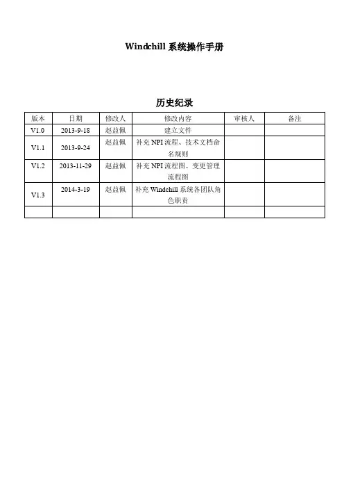
Wind chill系统操作手册历史纪录目录WINDCHILL系统操作手册 (1)W INDCHILL系统简介 (3)注意事项与操作技巧 (4)W INDCHILL系统各团队角色职责 (5)第一章总体设计 (7)第二章环境配置 (8)2.1修改HOSTS文件 (8)2.2修改IE设置 (8)2.3安装JRE6 (10)2.4修改用户名与密码 (10)2.5安装常用插件 (12)第三章基本操作 (15)3.1通用操作界面 (15)3.2导航栏 (17)第四章产品模块 (18)4.1产品创建 (18)4.2添加团队成员 (19)第五章项目模块 (22)5.1项目创建 (22)5.2维护项目团队 (24)5.3维护项目计划 (27)第六章通用业务操作 (33)6.1文件夹管理 (33)6.2文档管理 (35)6.3图纸管理 (40)6.4部件管理 (43)6.5NPI流程 (48)i.Sap-零件NPI流程图 (49)ii.Sap-电子物料NPI流程图 (53)iii.Sap-组件NPI流程图 (54)iv.Sap-产品NPI流程 (54)v.Sbom-虚拟件 (54)6.6变更管理 (55)i.电子物料变更流程 (61)ii.机械物料变更流程图 (63)iii.组件变更流程流程图 (63)第七章水印 (64)第八章任务委派 (65)第九章技术文件命名规则 (67)7.1概述 (67)7.2开发文档命名规则 (67)Wind chill系统简介PLM简介PLM,全称ProductLifecycleManagement,是一种企业信息化的商业战略。
它实施一整套的业务解决方案,把人、过程和信息有效地集成在一起,作用于整个企业,遍历产品从概念到报废的全生命周期,支持与产品相关的协作研发、管理、分发和使用产品定义信息。
PLM为企业及其供应链组成产品信息的框架。
它由多种信息化元素构成:基础技术和标准(如XML、视算、协作和企业应用集成)、信息生成工具(如MCAD、ECAD和技术发布)、核心功能(如数据仓库、文档和内容管理、工作流和程序管理)、功能性的应用(如配置管理)以及构建在其他系统上的商业解决方案Windchill系统简介Windchill是PTC公司推出的一套集成应用软件,为众多PLM系统中的一种国际主流软件,用来管理产品和工序的整个生命周期.它充分利用了Internet和相关的信息技术,为系统提供了一种应用软件基础,从而保证能快速、高效地部署产品信息应用软件。
H1V2.1使用说明书
黄 冈----------------------------18 英 语 类- - - - - - - - - - - - - - - - - - - - - - - - - - - - - - 1 8
词 典- - - - - - - - - - - - - - - - - - - - - - - - - - - - 2 2 词 典- - - - - - - - - - - - - - - - - - - - - - - - - - - - - - - 2 2 用 户 词 典- - - - - - - - - - - - - - - - - - - - - - - - - - - - 2 4 整 句 翻 译- - - - - - - - - - - - - - - - - - - - - - - - - - - - 2 5
本机与电脑连接时 ①本机与电脑连接时,必须 处于开机状态,否则电脑不 能识别本机。 ②为了本机使用安全,在本 机与电脑连接时,小机端必 须进入“USB”连接界面后, 电脑才能识别到本机。
关于电池 本机使用充电锂电池。 在工作状态下,当屏幕显示暗 淡或提示电量低时,请尽快充 电或更换电池。电量低时如果 正在播放MP4、MP3,可能出现 机器自动重启或关机的现象。
损 失 , 本 公 司 概 不 负 责 。 本公司不断致力于提高、完善产品的质量,强化 功能,软件功能也在不断更新完善,产品说明书所 载功能介绍以出厂预置内容为准,因此任何以本说 明书的数据、图示或文字描述为依据的索赔要求将 不予接受。 因本机数据庞大,经过工作人员的仔细审核及校 对后,如仍有疏漏,敬请指正并原谅。
本机是一款触摸式+按键式的双模式操作学习工具,大部分 功能均可通过手动点击显示界面进行操作,也可直接操作整机上 的按键来实现功能。 为便于用户操作,本说明中采用两种标识来标注整机按键名 称与界面中按钮名称,以示区分。 【 】: 标注整机上按键名称。如【左右】键,表示可操作整机上的“ 、 ”键或“ 、 ”键实现功能。 〖 〗: 标注显示界面上的各按钮、标识、图标等。
V2.1中性说明书
目录1 产品介绍 (5)1.1 产品概述 (5)1.2 产品主要功能 (5)2 安装指南 (7)2.1 清点设备及其附件 (7)2.2 安装硬盘 (7)2.3 后面板物理接口连接说明 (8)2.4 报警线连接说明 (28)3 操作必读 (31)3.1 前面板说明 (31)3.2 遥控器说明 (38)3.3 菜单项说明 (39)3.3.1 菜单导航 (39)3.3.2 菜单操作规则 (40)3.4 输入法规则说明 (42)4 基本操作 (43)4.1 开机 (43)4.2 预览 (43)4.3 修改用户密码 (44)4.4 云台控制 (45)4.5 手动录像 (46)4.6 回放 (46)4.7 录像资料备份 (49)5 参数设置 (52)5.1 基本设置 (52)5.1.1 修改管理员密码 (52)5.1.2 添加与删除用户 (54)5.1.3 设备名称与设备号 (55)5.2 本地预览设置 (55)5.2.1 视频输出制式 (55)5.2.2 VGA设置 (55)5.2.3 OSD设置 (55)5.2.4 视频输入参数设置 (56)5.2.5 区域遮盖设置 (56)5.2.6 本地预览属性设置 (58)5.3 报警设置 (58)5.3.1 信号量报警 (58)5.3.2 移动侦测报警 (60)5.3.3 视频丢失报警 (62)5.3.4 遮挡报警 (63)5.4 录像设置 (64)5.4.1 录像图像参数设置 (64)5.4.2 录像计划表设置 (65)5.4.3 事件压缩 (66)5.5 网络设置 (66)5.5.1 网络基本设置 (66)5.5.2 NTP校时、DDNS设置 (67)5.5.3 NAS设置 (68)5.5.4 邮件服务设置 (68)5.6 云台控制设置 (69)5.7 异常处理 (70)5.8 串口设置 (71)5.9 交易信息 (71)6 管理工具 (74)6.1 保存设置 (74)6.2 恢复设置 (75)6.3 升级 (75)6.4 硬盘管理 (76)6.5 清除报警 (76)6.6 重新启动 (76)6.7 关机 (76)6.8 日志查询 (77)6.9 查看系统信息 (77)附录1 安装硬盘总容量的参考计算方法 (78)附录3 技术指标 (83)附录4 常见故障解答 (92)1 产品介绍1.1 产品概述本设备是专为数码监控设计。
WebAccess IMM_Network 多媒体标牌管理系统 用户手册
用户手册WebAccess + IMMNetwork系列研华智能 多媒体标牌管理系统(网络版)版权声明随附本产品发行的文件为研华公司2015年版权所有,并保留相关权利。
针对本手册中相关产品的说明,研华公司保留随时变更的权利,恕不另行通知。
未经研华公司书面许可,本手册所有内容不得通过任何途径以任何形式复制、翻印、翻译或者传输。
本手册以提供正确、可靠的信息为出发点。
但是研华公司对于本手册的使用结果,或者因使用本手册而导致其它第三方的权益受损,概不负责。
认可声明Intel和Pentium为Intel Corporation的商标。
Microsoft Windows®为Microsoft Corp.的注册商标。
所有其它产品名或商标均为各自所属方的财产。
技术支持与服务1.有关该产品的最新信息,请访问研华公司的网站:2.用户若需技术支持,请与当地分销商、销售代表或研华客服中心联系。
进行技术咨询前,用户须将下面各项产品信息收集完整:–产品名称及序列号–外围附加设备的描述–用户软件的描述(操作系统、版本、应用软件等)–产品所出现问题的完整描述–每条错误信息的完整内容料号:2008PNWM31第二版中国印刷2015年3月WebAccess + IMM Network系列用户手册ii目录第 1 章 前言 (1)1.1软件应用与背景 (2)1.2注意事项 (2)1.3产品说明 (2)第 2 章 操作說明 (3)2.1系统登录 (4)2.2节目管理 (5)2.3时刻表管理 (8)2.4媒体管理 (11)2.5系统管理 (15)2.6派送 (19)2.7数据备份还原 (21)2.8退出系统 (23)第 3 章 简易示范 (25)3.1设置流程 (26)3.2媒体管理 (26)3.3编辑节目 (27)3.4素材选取 (27)3.5编辑时刻表 (29)iii WebAccess + IMM Network系列用户手册WebAccess + IMM Network系列用户手册iv第 1 章WebAccess + IMM Network 系列用户手册21.1软件应用与背景感谢您使用WebAccess + IMM Network 系列(以下简称本软件)。
視訊會議設備系統 操作說明说明书
SPEC視訊會議設備系統操作說明保管單位國立臺灣大學化學系-自然科學及永續研究推展中心保管人:賴彥佐目錄第一章基本須知 (1)第二章設備操作說明 (2)第一節設備基本介紹 (2)第二節操作說明與注意事項 (4)第三章使用情境介紹 (8)第一節化學系積學館B171會議室為例 (8)第二節化學系積學館B215會議室為例 (10)第三節化學系積學館B281會議室為例 (10)第四節電腦設定IP教學以Win10為例 (12)第五節化學系積學館教室需切換成自動IP模式之設定 (13)第六節化學系積學館教室切換回固定IP模式之設定 (15)第一章基本須知●本操作說明為輔助用,欲更加了解設備特性,務必先自行學習設備及軟體基本操作。
●須向本中心登記借出,並遵守借用規範,如未能配合,本中心保有審核之權利。
●如需使用系會議室空間,須先自行向系辦預約並領取鑰匙或門卡。
●筆記型電腦建議安裝以下視訊會議軟體:1.Webex(需自行申請、下載)https:///watch?v=sOiIpCOwyBM2.Google meet(需有Google帳號)https:///watch?v=jxce20kHFhE3.U會議(需自行申請、下載)https:///watch?v=TgesvtqNfjs4.OBS(免費直播軟體,可視情況搭配視訊會議使用)https:///watch?v=FKlqRoJ_2Jk第二章設備操作說明第一節設備基本介紹●強烈建議使用有線網路,或穩定之無線網路亦可。
●主要使用設備需求為:1.筆記型電腦1組2.視訊會議推車組A.推車及相關設備,如圖1B.遙控器,如圖2C.麥克風,如圖3D.麥克風3.網路分享器4.多功能USB HUB(可視情況選擇使用,如使用MAC系列筆電)圖1推車及相關設備圖2遙控器圖3麥克風第二節操作說明與注意事項1.前置作業A.先檢查該空間是否有正常網路(含網路線)可使用B.若無網路線則將分享器連接至電腦C.再將視訊會議推車組連接到電腦即可I.將推車USB線(於推車桌面並有白色標籤)連接至電腦USB孔II.將推車後面下方3孔電源線接至插座或延長線III.開啟視訊會議軟體並選擇以Rally攝影機、Rally喇叭、Rally麥克風即可D.若要同步電腦螢幕至其他螢幕,如投影幕、互動電視等,再將對應的HDMI或USB等線接至電腦即可2.設備操作A.Rally攝影機可搭配遙控器操作方向與遠近,如圖4B.Rally喇叭有兩台分別至於推車中,僅能播放對方端聲音C.Rally麥克風正面上方按鈕可觸控,當按鈕呈現白色即代表可收音,當按鈕呈現紅色即代表靜音D.其他設備介紹可參考連結並下載https:///eEQr6Q圖4遙控器說明來源: 羅技Rally操作手冊3.注意事項A.抽屜強烈建議勿更動以免影響線路B.若無任何反應請注意電源線是否有通電,或是再重新插入至電腦其他USB孔C.亦可搭配直播,建議使用較高階電腦,否則會有過熱或當機情形D.注意會議空間各裝置位置、插座與空間大小,視訊會議裝置推車須有一定使用空間E.建議另外擺放電腦,避免影響鏡頭視線F.視訊會議裝置之麥克風會收到現場所有聲音G.若要調整高度可於推車右後方油壓桿操作H.推車中間左後方有插座可使用I.移動推車時,請握鏡頭下方之黑色桿子與白色桌子拉把移動J.若要使用MACBOOK 系列電腦A.搭配多功能USB HUB即可B HUB多會有Type-C 端接入對應孔即可K.若要搭配直播A.至少兩位,一位講者,一位負責操作軟體與鏡頭B.操作軟體者須熟悉OBS第三章使用情境介紹第一節化學系積學館B171會議室為例1.想將電腦螢幕同步至另一螢幕,須將HDMI線段插入至筆電HDMI孔即可。
- 1、下载文档前请自行甄别文档内容的完整性,平台不提供额外的编辑、内容补充、找答案等附加服务。
- 2、"仅部分预览"的文档,不可在线预览部分如存在完整性等问题,可反馈申请退款(可完整预览的文档不适用该条件!)。
- 3、如文档侵犯您的权益,请联系客服反馈,我们会尽快为您处理(人工客服工作时间:9:00-18:30)。
数字标牌联网信息发布系统用户手册2012年9月成都瑞博智能信息系统有限公司目录1.安装与部署 (3)1.1系统运行环境 (3)1.2系统安装 (3)1.3系统配置 (4)1.4系统授权与运行 (4)1.5系统升级 (4)1.6系统卸载 (4)2.使用入门 (4)2.1如何登录系统 (4)2.2如何添加终端设备 (5)2.3如何添加素材 (6)2.4如何添加节目 (7)2.5如何将节目下发给终端 (11)3.高级功能 (11)3.1如何启用终端 (12)3.2如何设置终端的输出模式 (12)3.3如何设置终端的网络参数 (12)3.4如何设置终端的工作时间段 (13)3.5如何用U盘更新终端数据 (15)3.6如何升级终端 (16)3.7如何预先下载素材资源 (18)3.8如何添加和使用网页数据 (19)3.9如何编辑金融数据模板 (21)3.10如何添加流播素材 (22)3.11如何添加和使用场景 (23)3.12如何设置节目的播放时段 (25)3.13如何管理终端上播放节目 (27)3.14如何管理用户及权限 (28)4.辅助功能 (30)4.1如何管理终端分组 (30)4.2如何管理素材目录 (31)1.安装与部署1.1系统运行环境软件要求操作系统:Windows XP、Windows 2003、Windows 7系统框架:.net Framework 2.0Web应用服务器:Apache 2.2数据库服务器:MySQL 5.2FTP文件服务器:FileZilla ServerNTP对时服务器:NTP Service硬件要求CPU:2.0G及以上硬盘容量:80G及以上内存容量:512M及以上网络带宽:10M及以上显示分辨率:1024 x 768及以上1.2系统安装安装前,建议临时关闭360安全卫士等实时监控软件,避免安装过程中的频繁提示给您造成不便。
为便于系统安装,安装文件中已包含以下所需软件:. net Framework 2.0、Apache 2.2、MySQL 5.2、FileZilla Server、NTP Service双击安装文件,根据安装向导提示,即可完成整个安装。
安装期间,系统将根据当前系统的运行环境自动安装上述内容。
安装过程中需设置当前服务器IP、应用服务器端口(默认3080)、数据库端口(默认3036)和FTP端口(默认3021,数据端口:10000-10050)。
请确保所设置的端口在防火墙中已开放。
安装结束后,系统将创建并自动开启以下服务:DSS_WEB(应用服务):提供“管理系统运行、处理终端数据请求”服务DSS_FTP(文件服务):提供“素材文件的上传与下载”服务DSS_DB(数据库服务):提供“业务数据的存储与检索”服务DSS_NTP(对时服务):提供“终端自动对时”服务1.3系统配置当服务器IP地址出现变动,或需要调整原有相关服务器端口时,请进入程序菜单中的DSS目录,单击“服务器参数配置”,重新选择IP地址或输入新端口,单击“保存”按钮,系统将自动重启服务使之生效。
请确保所设置的端口在防火墙中已开放。
1.4系统授权与运行进入程序菜单中的DSS目录,单击“DSS 管理系统”,在登录系统前,系统将验证授权信息,如果未授权或授权已过期,系统将弹出授权注册窗口,请提供上面显示的机器码,我们将生成对应的授权文件(license.lic),在获得授权后,单击“注册”按钮,选择授权文件,单击“确定”即可完成系统授权。
授权验证通过后,即可进入管理系统。
1.5系统升级系统升级过程同系统安装,无需卸载,直接运行新的安装文件即可。
升级安装时,需选择原安装路径。
1.6系统卸载进入程序菜单中的DSS目录,单击“卸载DSS 管理系统”,根据提示即可完成系统的卸载。
卸载过程中请留意“是否保留历史数据”的提示,当需要保留所有上传的素材与业务数据时,请单击“是”,否则将彻底删除所有数据。
2.使用入门2.1如何登录系统双击桌面图标,进入系统的登录界面。
点击按钮,设置服务器地址、端口和语言。
,服务器地址可以用IP地址也可以使用域名,端口默认为3080,请根据实际部署进行配置。
填写用户名及密码,系统默认用户名:admin,密码:123点击,系统将会验证当前的用户及密码,验证通过后进入主页面。
2.2如何添加终端设备点击快捷菜单栏里的,或菜单栏“终端管理”下的“终端配置”,即可进入终端配置页面。
点击,进入终端编辑页面。
常规设置选项卡中请填写终端编号,序号列号及名称。
终端编号格式为:DSTXXXXX(X:表示数字),可点击,系统则会自动分配编号;序列号栏填写终端的出厂序列号,可通过每个终端硬件盒上的标签获得;终端名称栏填写终端的标识名称,便于日常管理维护。
点击“保存”,即可添加该终端2.3如果添加素材点击快捷菜单栏里的,或菜单栏“资源管理”下的“素材管理”,即可进入素材管理页面。
支持的素材列表如下:视频:mpg/vob/avi/wmv/mkv/mov/mp4/ts,音频:mp3/wav文本:txt,幻灯片:ppt/pptx添加素材前,建议先建好素材目录,便于日后检索创建目录:单击“新建”下拉中的“目录”按钮,在光标处输入目录名称,按回车键确认保存,当需要创建子目录时,双击父目录进入,然后再进行添加操作进入目录与返回:双击目录名称即可进入该目录。
双击列表第一行带向上箭头的路径名称,即可返回上级目录删除目录:选中要删除的目录后,单击“删除”按钮,待确认后即可删除选中的目录,目录下的所有子目录和素材将一并删除修改目录名称:选中要修改名称的目录后,单击“重命名”按钮,在光标处重新输入目录名称,按回车键确认保存调整目录从属关系:选中要调整从属关系的目录,拖到目标目录即可;当需要将目录移到上级目录时,拖到向上箭头处即可。
当需要跨多级目录调整时,请进入“素材目录设置”模块进行操作添加素材:在“本地浏览”列表中,选中需上传的文件后,单击“导入”按钮即可上传到素材库的当前目录;也可直接拖动文件到素材库的指定目录中(注:文本素材,字数限制在500个字,当文本文件中的字数大于该限制时,将被自动截取)。
2.4如何添加节目点击快捷菜单栏里的,或菜单栏“节目管理”下的“编排发布”,进入节目管理列表页面。
点击,进入节目编辑页面,填写节目基本信息。
播放等级有,垫片、循环、定时、插播四种模式,播放等级依次提高;可见范围分公开和私有两种,前者表示该节目为公共资源,其他用户可以变更该节目,后者表示该节目为私有资源,不对其他用户开放。
填写完基本信息后,进入节目编辑主页面。
1)可选素材区分素材库和对象两个选项卡,其中素材库显示系统可用素材列表,对象选项卡提供时间、星期、日期、直播、文字等素材对象。
2)工具栏区◆分辨率调整选项:调整场景的分辨率。
◆编辑区缩放阀:调整编辑区的显示大小◆编辑锁定按钮:控制场景可编辑与不可编辑◆添加窗口按钮:添加一个空白播放窗口◆删除窗口按钮:删除选定的播放窗口◆上/下/左/右对齐按钮:对齐多个选定的播放窗口◆上/置顶/下/置底按钮:调整播放窗口的上下层次3)编辑区场景编辑时,可拖动一个或多个素材到编辑区,当素材拖到位置没有播放窗口时,系统将自动创建播放窗口用于包含这些素材;当素材拖到已有窗口的中心区时,素材将追加到该窗口中。
编辑区的一些快捷键使用说明:◆ctrl键+ 鼠标滚轮,缩放编辑区◆ctrl键+ 素材拖动,禁止素材拖到现有窗口中◆ctrl键+ ↑键,选定窗口上对齐◆ctrl键+ ↓键,选定窗口下对齐◆ctrl键+ ←键,选定窗口左对齐◆ctrl键+ →键,选定窗口右对齐◆↑键,选定窗口上移◆↓键,选定窗口下移◆←键,选定窗口左移◆→键,选定窗口右移4)右键菜单在编辑区中单击鼠标右键,列出上图所示菜单。
其中:◆设为全屏背景当前窗口的当前素材为图片时,该按钮可用,单击可将该图片素材设置为全屏背景图,若需取消全屏背景图,先单击选中“背景区”,然后在“播放素材区”中删除该素材即可。
◆临时隐藏窗口单击隐藏当前选中窗口,若需恢复显示,请勾选“播放窗口”中对应窗口的“见”复选框。
5)播放窗口区列出当前场景的所有播放窗口,选中窗口后,在“窗口信息”栏中可设置具体参数,当设置窗口背景颜色时,将自动取消窗口的背景图。
每个场景默认有个特殊的窗口:背景区,用于存放音频素材。
6)播放素材区列出当前选中窗口的所有播放素材,选中素材后,在“素材信息”栏中可设置具体参数,当选中多个同类型素材时,可进行批量设置;单击“预览”按钮可预览查看。
节目编辑完成后,点击中的,即可保存当前节目。
2.5如何将节目下发给终端进入节目编辑页面,点击中的,进入终端选择页面。
在可选终端列表中,勾选需要播放的终端设备,然后点击“确定”。
如果需要将节目从终端上移除,可在已选终端列表里移除相应的终端,然后点击“确定”。
3.高级功能3.1如何启用终端当终端主动查找服务器时,服务器自动添加该游离终端,如果需要使用该终端,就必须先启用。
进入终端配置页面,选择需要启用的终端设备(状态为或)选择菜单下的“启用未知终端”即可,或进入终端编辑页面,在常规设置选项卡中,勾选,然后保存。
3.2如何设置终端的输出模式终端可选输出模式有AV、VGA、HDMI、LVDS四种,其中LVDS(低压差分信号)主要用于液晶屏对接。
各个类型均有相应的输出分辨率,可通过菜单栏“终端管理”下的“屏参配置”页面进行维护。
进入“终端编辑”页面的“输出设置”选项卡勾选“启用输出设置”,选择屏幕类型、输出类型及分辨率,保存即可。
3.3如何设置终端的网络参数进入“终端编辑”页面的“网络设置”选项卡勾选“启用网络设置”,选择相应的联网方式(以太网或WI-FI)及IP地址分配方式(自动获取或使用固定IP)WI-FI联网方式还需要额外参数,请在“无线设置”选项卡中进行配置(需要无线路由器相关信息)。
配置完成后,点击“保存”即可。
3.4如何设置终端的工作时间段进入“终端编辑”页面的“工作时间段设置”选项卡勾选“工作时段”,然后点击“添加”,进入“工作时段编辑”页面指定工作日开关机(已周末关机为例),勾选“日期设置”并选择“指定星期”,然后勾选工作日,并设置时间段后保存该记录,如下图所示。
再新增一条工作时段,重复上述步骤,选择指定星期关机,配置如图所示,然后保存。
(注:如果无显式指定关机日期,终端将采用默认全天开机)工作时段记录如下:最后,保存终端配置即可3.5如何用U盘更新终端数据进入终端配置页面,选择需要升级的终端设备点击“更多”菜单下的,进入终端数据导出页面选择导出内容和路径,导出成功后,将会在目标路径升级“dst”目录,该目录为终端唯一识别目录,包含以下文件及目录将整个“dst”目录复制到U盘根目录,然后将U盘插到终端的USB端口进行升级3.6如何升级终端点击菜单栏“终端管理”下的“终端升级”项,进入终端升级页面点击,导入升级包文件选中导入的升级包,点击右侧的,添加需要升级的终端,保存即可。