EVA4400安装手册
EVA4400 iSCSI安装使用说明
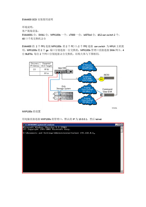
EVA4400 iSCSI安装使用说明环境说明:客户现场设备:EVA44001台;SMA1台;MPX100b一个;c7000一台;bl870c4台;4/12 san switch 2个;48口千兆交换机2台EVA4400的2个FP1连接MPX100b 的2个FC口;2个FP2连接san switch 为HPUX主机使用;MPX100b的2个ge 端口分别连接一台交换机;MPX100b管理口直接连接SMA网卡;4台BL870c 每台2个网口分别连接2台交换机;结构大体与下图相同:MXP100b的设置用电脑直接连接MXP100b的管理口:默认的IP为10.0.0.1,然后telnet用户名:guest密码:password然后:admin start 密码:config在这里可以更改mgmt也就是管理口的IP,命令:set mgmt查看FC口的信息:show fc设置Ge端口的地址,将来客户端连接的时候需要链接的IP地址,set iscsi 1(2)EVA4400 的设置:1.mxp100b的管理端口连接EVA SMA的一个网口并将SMA 网口的地址设置为与MXP100b相同网段的地址,并保证能PING通;(好像直接连接EVA自身的管理口也可以,有待进一步验证);2.在SMA安装command view(这个没有截图,正常安装就可以,需要注意的是在同时连接FC 和MPX100b后安装时会有两个选项FC 控制方式和iSCSI控制方式,我当时选FC方式,我的理解是那种都可以3.Login后就会看到多出一个iSCSI device的选项4.Click Discover iSCSI Devices5.这时就会看到多出一个iSCSI 控制器(控制器的IP地址就是MPX100b的mgmt口的IP)有更改成功)7.iSCSI 控制器的FC口信息8.添加主机(首先要在客户机的iSCSI发起端发起,才能在host list 里面看到主机)9.Present disk10.正常的EVA功能11.Vdisk信息12.Present disk给bl870c13.连接到iSCSI 控制器后会自动有一个iSCSI MPX host 加到host列表里面;Windows客户端添加14.HPUX 看到的EVA disk(这里主要说明下是EVA的FC方式和iSCSI 方式可以同时使用)。
EVA4400配置
上海远图电脑科技有限公司EVA4400安装操作手册 硬件组成: 1. 双控制器2. 盘笼两个,450G*143. 管理卡 准备工作:1. EVA 安装,请参考安装手册,需要注意的是loop 的连接顺序2. License 的获取,随包装会有一份信函,上面有你所需要的信息。
然后到相关网站注册,获取license 就可以在以下步骤使用了。
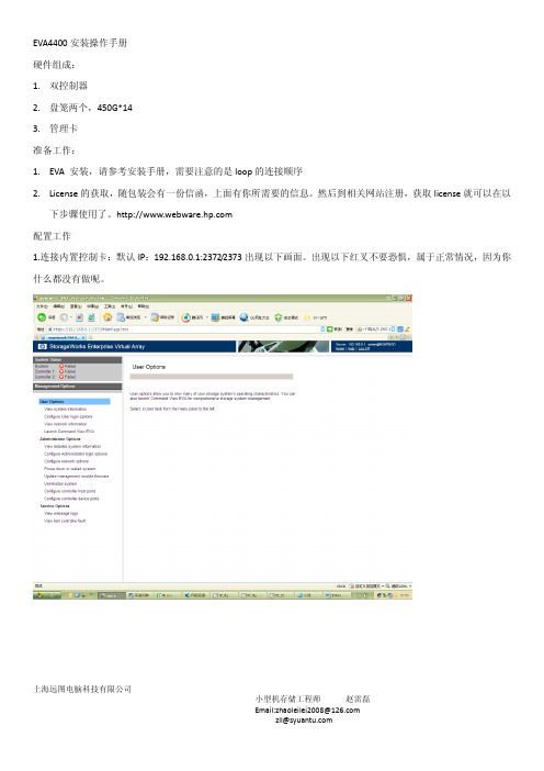
配置工作1.连接内置控制卡:默认IP :192.168.0.1:2372/2373出现以下画面。
出现以下红叉不要恐惧,属于正常情况,因为你什么都没有做呢。
上海远图电脑科技有限公司2.登陆COMMOND VIEW ,找到这个选项,点击进入Commond View 操作界面3.页面提示信息可以看到没有安装license 许可呢,我们要做的是先初始化系统。
上海远图电脑科技有限公司4.填写好相关的参数,执行初始化操作上海远图电脑科技有限公司5.新系统,初始化很快,3分钟左右已经完毕上海远图电脑科技有限公司6.看到提示,需要安装LICENSE上海远图电脑科技有限公司7.在如图所示的对话框中,把你申请的license 许可码黏贴到其中,注意不要多余的符号8.我的是无限制容量的licesen,贴上来吧,但是不怕抄袭,因为是跟wwn 号绑定的。
点击install license 按钮,瞬间可以安装完成上海远图电脑科技有限公司9.现在可以看到如下图的内容,说明应经安装成功,刷新一下,就可以继续接下来添加VDISK 、HOSTS 等操作了.下面我们要做的是配置HOSTS,VDISK 并且present 到相关的主机 1.用户名:admin 密码为空上海远图电脑科技有限公司1.在HOSTS 中,如果主机很多,可以创建相关的文件夹。
如我所创建的RX66002.在创建的hosts 文件夹中可以添加相关的host,ADD HOST上海远图电脑科技有限公司3.可以给hosts 起一个通俗易懂易于辨认的名字,根据自己的需要选择配置参数,如果不知道参数有什么用,可以选择后面的小问号查看参数解释。
4400直埋字体适配器安装说明书

PageБайду номын сангаас1
97864C (Rev. D - 06/16)
4400 Direct Bury Fountain Adapter
PARTS LIST
ITEM NO.
1 2 3 4 5 6
PART NO.
45835C 75617C 75616C 70204C 75611C 70421C
DESCRIPTION
5. After sufficient cure of concrete, remove flange bolts and washers.
6. Mount fountain assembly per instructions supplied with fountain and Items 4, 5, & 6 (See below).
INSTALLATION INSTRUCTIONS
1. Thread nuts (Item 3) onto rods (Item 2) (one nut per rod).
2. Thread rods into adapter cylinder (Item 1) and tighten nuts against cylinder securely.
3. Place washers (Item 6) on bolts (Item 4) (one washer per bolt). Assemble bolts into adapter flange. Thread bolts all the way in.
4. Secure adapter into concrete forms as per Standard Practice and as shown below. Be sure to align adapter for proper location of Water inlet line, Drain line, and required fountain alignment.
磁盘存贮器(HP eva4400)详细需求

容量
本次配置容量=18TB,最大容量可扩展至96TB
IPOS
140000
支持主机个数
256
客户端支持
不收费
带宽
>=1550MB/s
最大Raid集
最大RAID集的磁盘数量≥16
是否OEM
需要原厂商设备,非OEM产品。
操作系统
控制器采用专用操作系统(非Windows、linux的改造版)
磁盘混插
在同一硬盘笼内实现FC和ATA硬盘混插
磁盘存贮器(HP eva4400)详细需求
指标
描述
品牌
HP
机型
全光纤架构SAN磁盘阵列
阵列控制器
标配2个RAID控制器实现冗余,采用Risc处理器。
阵列高速缓存
当前配置阵列高速缓存必须满配且数量=4GB
后端接口类型
FC:4(4Gb)
后端通道数量
4
最大硬盘个数
最大硬盘个数>=90
硬盘可靠性
在有冗余硬盘空间的情况下,同一个Raid组中,支持超过2块以上的硬盘渐次损坏
后端交换架构
磁盘阵列使用交换架构连接后端磁盘抽屉
主机连接
在阵列允许的情况下,不限制安装主机数量,未来增加任意平台,任意主机数量不需要额外付费。如需付费,请投标时配齐。
RAID支持类型
支持VRAID0,VRAID1,VRAID10、VRAID5
EVA4400 简单配置手册

EVA4400 简单配置手册
测试机型:
HP ProLiant DL360 G7
CPU: Intel Xeon 2.27Ghz
内存:2G
硬盘:146G SAS
EVA:4G FC
配置步骤:
1.运行桌面图标Command View EVA
2.配置界面是基于WEB,所以会自动打开浏览器进入登录页面
登录页面基于WEB,可直接运行Command View EVA图标进入,也可在IE 地址栏处输入EVA IP地址192.168.0.1:2373 默认用户名admin 没有密码3.登录后可看到初始页面
4.选择Hosts图标,点击Add Host按键来新建主机信息
5.选择Virtual Disks图标,点击Create Vdisk按键创建虚拟磁盘并映射主机
创建虚拟磁盘时,可以选择RAID级别并自定义可用容量。
选择Present to host 映射主机名称。
6.打开磁盘管理器并重新扫描磁盘
发现新驱动器,分区并格式化后即可使用。
小测试:
从380 G6服务器拷贝2.75G的一个ISO文件到EVA,时间为30秒左右。
(4G 光纤直连)。
4400系列电源包安装和操作说明书
PERLICK CORPORATION 8300 W. Good Hope Road, Milwaukee, WI 53223 • 800.558.5592 • MODELS 4400 Series 44044414-23044104410W 44144414W 44204420WCUSINSTALLATION AND OPERATION INSTRUCTIONS4400 SERIES POWER PAKSIMPORTANT INFORMATIONTo register your product, visit our web site at . Click on Commercial , then Service . You will see the link to Warranty Registration Form . You must complete and submit this form or the installation date will revert back to the ship date.Permanently mount the enclosed Warning/Safety Instruction label in a visible location near the CO2 regulator.This manual has been prepared to assist you in the installation of your Century Remote Beer System and to acquaint you with its operation and maintenance. We dedicate considerable time to ensure that our products provide the highest level of customer satisfaction. If service is required, your dealer can provide you with a list of qualified service agents. For your own protection, never return merchandise for credit without our approval.We thank you for selecting a Perlick product and assure you of our continuing interest in your satisfaction.Table of ContentsSizes & Specifications ............................................2-3 Air-Cooled Models .................................................2 Water-Cooled Models ............................................3 General Information ..........................................4 Installation ........................................................5 Connecting Power Pak to Trunk Housing ..............6 Connecting to Trunk Housing ................................7Power Pak Start-Up ...................................................8LEDS .........................................................................9Preventative Maintenance .........................................9Replacement Parts ..................................................10Wiring Diagrams (11)Form No. Z2020Rev. 11.30.2022(Ground, Neutral, Hot-Power, Hot-Power)AC: 115 - 208/240v, 60 HZ, Split Single PhaseC US(Ground, Neutral, Hot-Power, Hot-Power)AC: 115 - 208/240v, 60 HZ, Split Single PhaseCUSPRODUCT DESCRIPTIONPower Paks have always been an integral part of a Perlick Century Beer System. The 4400 Series Power Pak product line has been expanded to satify longer beer runs. A Power Pak circulates coolant solution (food grade propylene glycol with distilled water) fromwalk-in cooler to the dispensing station(s) and back,maintaining the desired dispensing temperature at the faucet. The 4400 series Power Pak incorporate a 1/3 hp ball bearing, maintenance free motor with a 100 gallon per hour 150 psig positive displacement pump for optimum performance. The 4400 series Power Pak product line employs a direct expansion form of refrigeration increasing the units’ efficency aswell as making the units more compact. These unitsalso employ an electronic temperature control with digital readout. This state of the art control controlsthe performance of the unit as well as giving theuser a visual indication of the how the unit is workingas well as giving the user a visual indication of the how the unit is working as well as early indication if something may be going wrong through the use of internal alarms.AccessoriesPower Cord KitC2296A-20--12/3 Cord, 20A, Nema Plug 5-20P, Dedicated Circuit Models - See above electrical specificationsPower Pak Racks61790, 61790+1, 61790+2 - All ModelsPower Pak Wall Mounting BracketsFor Models 4404 & 4410 onlyCoolant Solution-63299-1One gallon Perlick Coolant solution, 30% DowFrost HD/70% Distilled Water Coolant Connector Kit 63335 - All Models Leg Set - All Models57782 . . . Set of four, 5 3/4”-71/2” adjustable legsPump Kits4430 - Pump kit, 115V, 6.1 A, 100 gph, 130 psigModels 4410, 4410W4431 - Pump kit, 115V, 5.6 A, 100 gph, 130 psig Models 4414, 4414W4432 - Pump kit, 230V, 2.8 A, 100 gph, 130 psig Models 4414-230, 4420WARNING: California Prop 65 NoticeThese products may expose you to chemicals i ncluding Chromium, which are known to t he state of California to cause cancer and b irth defects or other reproductive harm. For more information on whether a product in this list contains these chemicals, please refer to the specific product page at . Or to find out more about Prop 65, go to .4400 SERIES POWER PAKS - INSTALLATIONOperation/Installation ManualINSTALLATIONIMPORTANT SAFETY WARNINGS!• Follow all National and Regional Codes.• Read Installation and Operating Instructions carefully before attempting to install, operate or maintain the product.• Protect yourself and others by observing all safety information.• Electrical hazards exist and can cause injuries if not serviced by properly trained personnel.• Failure to comply with instructions could result in personal injury and/or property damage!• Retain instructions for future reference.• Never operate the circulating pump without coolant in the reservoir.NOTE: Air-cooled Power Paks must be installedin areas with adequate ventilation to maintain ambient temperatures of less than 105°F to achieve optimum performance and satisfy warranty requirements.INSTALLING THE POWER PAKPrior to installing a 4400 Series Power Pak, it isimperative that the method of connecting it to theelectrical service has been determined. Ensure thatthe electrical service to power the Power Pak willhandle the load requirements. Perlick has a PowerCord specifically designed for a Power Pak, which has a RLA of 16 amps or less, and a MCA of 20 amps orless. All units with RLA greater than 16 amps and aMCA of greater than 20 amps should have the Power Pak hard-wired to electrical service.ALL MODELS• Determine the ideal placement of the Power Pak.Locate the connection point to the truck housingand place the Power Pak as close to this point aspossible. NOTE: If the Power Pak is to be located on top of the walk-in cooler, it is imperativethat proper ventilation is provided to preventsystem failure due to overheating. Inadequateventilation will void warranty.• Place the Power Pak and Ensure that it is level to provide proper overflow protection. REMINDER: Allow a minimun of six inches of clearace on the louvered ends of the cabinet for proper airflow. Allow accessibility room on the top of the cabinet for serviceability.• Remove the top panels (2).• Ensure Power Switches for Condensing Unit and Pump(s) are in the OFF position. Make the electrical connections per ther illustrations. NOTE: Electrical circuit shold be a dedicated circuit for use only with the Power Pak. The circuit should be sized in accordance with the electrical requirements of each unit as well as in compliance with all National and Local Codes.• Plumb overflow port to a suitable reservior/drain.WATER-COOLED MODELS• In addition to the above installation instruction:• Care should be exercised in locating the PowerPak so that the unit will never be exposed to temperatures below freezing.• If the Power Pak is installing more than 5 feet higher than the remote outlet drain point (i.e., location of the floor drain) of the condenser, a vacuum breaker or open vent line should be provided to prevent the discharge line from creating a partial vacuum condition in the condenser water system.• If a water-circulating pump is used it should beplaced on the water supply side of the condenser, so water is being pushed through the condenser.• A potable water supply is required aswell as a drain or reclamation system. Make water supply connection to fitting labeled as the water inlet. Make outlet connection to fitting labeled as the water outlet connection. Both the inlet and outlet fittings supplied with the Power Pak are 1/2” Quick Connect fittings.• This equipment when equipped with a water-cooledcondenser, connected to a portable water supply system is to be installed with adequate backflow protection to comply with applicable federal, state and local codes.(Backflow protection not included.)CONNECTING POWER PAK TO TRUNK HOUSING 400 Series Power Paks require rigid fittings with a minimum pressure rating of 150 psig. Use Coolant Connector Kit #63335 to connect Power Pak to Trunk Housing.• Inspect pump outlet port for debris. Insert barbed fitting #63307 into pummp outlet port.• Inspect Glycol Return Manifold inlet for debris.Insert barbed fitting #63307 into return manifold inlet port.• Cut supplied coolant tubing, #54588, to required length to reach from Power Pak to Trunk Housing connection point.• Cut tubular insulation sleeve, #C12700, in half and install over previously cut coolant tubing.• Take Oetiker clamps, #54871-210, and install over coolant tubing ends.• Push coolant lines, one each over pump outlet barbed fitting #63307 and return manifold barbed fitting #63307.• Position Oetikers over barbed fitting and clamp securely.• Slide tubular insulation sleeves tightly against connection points. Use insulation tape as necessary to ensure an air tight seal to prevent excessive heat gain or condensation problems.• Drill a 3-1/2” diameter hole in walk-in cooler to accommodate coolant lines.• Install insulation donuts over hole (both inside and outside of cooler walls.• Slide large insulation sleeve, #57478, over remaining coolant tubing exposed to warm air conditions including inside walk-in cooler from Power Pak to Trunk Housing connection point. Seal and tape all seams to prevent excessive heat gain or condensation problems.• Slide coolant lines through 3-1/2” donut hole previosly cut in walk-in cooler wall.• Position Trunk Housing coolant lines and Coolant Connector kit lines in horizontal position, to alleviate condensation runoff into Trunk Housing.• Cut Trunk Housing coolant lines with tubing cutter to ensure clean burr free ends.• Take Oetikers clamps #54871-210, and install over coolant connector kit tubing ends.• Slide coolant connector kit tubing over the trunk housing coolant lines and secure using the Oetikers.• Complete the insulation process by ensuring that all coolant lines are well insulated including all seams to prevent excessive condensation and heat gain.• Seal donut hole to ensure an air tight seal to prevent walk-in cooler problems as well as condensation. CONNECTING TRUNK HOUSING COOLANT LINES TO DISPENSING HEAD• Position the trunk housing so that beverage lines can be connected with a minimum cutting.• Split trunk housing approximately 12 inches from the end to allow working room for the connections.• Cut and deburr copper coolant lines coming from trunk housing and dispensing head. Stagger the lengths.• Connect trunk housing coolant lines to dispensing head coolant lines using clamps, hose and 3/8”x 1/2” union, included in Head connecting kit, #63486. Ensure that coolant lines are fully clample to guarantee a leak free connection.SYSTEM START-UPUse only Perlick Approved Coolant Solution, #63299-1, all other solutions and mixtures will void the Perlick warranty. The Coolant Solution has been pre-mixed for optimum performance and wear protection. The Power Pak resevoir holds approximately 1.75 gallons of solu-tion. It takes approximately 1 gallon of Coolant Solution to fill every 60 feet of Perlick Trunk Housing.• Never operate the circulating pumps without coolant in the resevoir.• Fill Power Pak resevoir with Perlick Coolant Solution.• Turn condensing unit switch and pump switch to the ON position. Coolant solution level will begin to drop in resevoir.• Continue adding Perlick Coolant Solution until no air bubbles are apparent from the Coolant return line. NOTE: Never allow for the Coolant level in the resevoir to drop below the heat exchanger tube inlet. Allowing the level to drop below the inlet will allow air into the lines.• Fill Power Pak reservoir until both the return line fitting port and the overflow tube port are submersed under Coolant Solution. Watch return line fitting port for additional Coolant Solution may need to be added.• Thoroughly check all field connection points for leaks.• Monitor Power Pak Temperature read-out to ensure Power Pak is working properly. Dependent on length of trunk housing run(s) and surrounding ambient conditions, these factors will determine how long it takes for the Power Pak to cut-out on the temperature control. DIGITAL TEMPERATURE CONTROLLERThe 4400 Series Power Pak comes equipped with a Factory Programmed Electronic Thermostat with display. The Thermostat has numerous factory settings, which should never be adjusted or tampered with to ensure proper operation of the Power Pak. The Thermostat has been factory programmed to cut-out at 30°F with a hysteresis/differential of 4°F.Front Panel Commands–Normal OperationSET:To display target set point.DEFROST:To start a manual defrost. (This feature is avail-able, however, the parameters for actuation are pro-grammed, such that, no defrost is available).Front Panel Commands–Programming Mode SET:Selects a parameter or confirms an operation.UP ARROW:Browses the parameter codes or increases the dis-played value.DOWN ARROW:Browses the parameter codes or decreases the dis-played value.Meaning of LEDSLED MODE FUNCTION SNOWFLAKE ON CompressorEnabled SNOWFLAKE FLASHING Programing Phase (flashingwith DEFROST) Anti-short cycledelay enabled DEFROST FLASHING Programming Phase (flashingwith SNOWFLAKE) Drip time inprogress DISPLAY MESSAGE MEANINGSMESSAGE MEANINGPOF Keyboard is locked out. Noparameters can be adjustedwithout unlocking the keyboard. ALARM MEANING ACTIONEE Data or Consult Factorymemory failureP1 Room probe Numerous - seefailure note 1NOTE 1: Faulty probe, loose connection, broket wire. (Power Pak will continue to operate with a faulty probe. The controller has been factory programmed to continue operation with the compressor cycling on and off in 5 minute intervals.How to see the SETPOINT• Press and immediately release the SET key: the display will show the Set point value.• Press and immediately release the SET key or wait for 5 seconds to display the probe value again. How to change the SETPOINT• Press and hold the SET key for more than 2 seconds to change the Set point value.• The value of the set point will be displayed and the SNOWFLAKE LED starts blinking.• To change the Set value, press the UP or DOWN ARROWS, dependent on the new set point value.• To memorize the new set point value, press the SET key again or wait 15 seconds.WARNING:IF MESSAGE OR INFORMATION SHOWN ON READOUT IS UNFAMILIAR, ALLOW CONTROL TO SIT FOR A MINIMUN OF 15 SECONDS AND CONTROLLER SHOULD RETURN TO DISPLAY PROBE TEMPERATURE.Perlick is committed to continuous improvement. Therefore, we reserve the right to change specifications without prior notice11Form No. Z2020Rev. 11.30.2022Wiring Diagram For 414-230, 4420, AC115 - 208/240, 60 HZ Power Paks (4 Wire AC Power Source Required)Wiring Diagram For 4404, 4410, 4414 115V Power PaksForm No. Z2020Rev. 11.30.2022 PERLICK CORPORATION 8300 W. Good Hope Road, Milwaukee, WI 53223 • 800.558.5592 • 。
EVA4400更换硬盘步骤
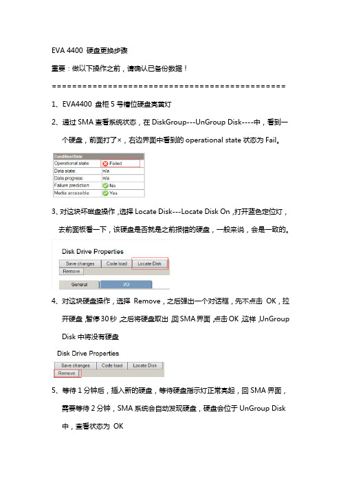
EVA 4400 硬盘更换步骤重要:做以下操作之前,请确认已备份数据!==============================================1、EVA4400 盘柜5号槽位硬盘亮黄灯2、通过SMA查看系统状态,在DiskGroup---UnGroup Disk----中,看到一个硬盘,前面打了×,右边界面中看到的operational state状态为Fail。
3、对这块坏磁盘操作,选择Locate Disk---Locate Disk On,打开蓝色定位灯,去前面板看一下,该硬盘是否就是之前报错的硬盘,一般来说,会是一致的。
4、对这块硬盘操作,选择Remove,之后弹出一个对话框,先不点击OK,拉开硬盘,暂停30秒,之后将硬盘取出,回SMA界面,点击OK,这样,UnGroup Disk中将没有硬盘5、等待1分钟后,插入新的硬盘,等待硬盘指示灯正常亮起,回SMA界面,需要等待2分钟,SMA系统会自动发现硬盘,硬盘会位于UnGroup Disk 中,查看状态为OK6、选择DiskGroup---Default Disk Group--Add Disks,在弹出的输入框输入数字1,因为我们本次只增加一块硬盘,之后点击确认。
7、观察状态,UnGroup Disk中的硬盘数再次为0,而Defalut Disk Group中会增加一块新的硬盘,同时,Defalut Disk Group会自动重分布数据,在Deafalut Disk Group界面,将会出现重分布进度,等到100%,数据重分布完成。
============================================== 注意:如果硬盘刚坏不久,阵列会先进行数据重构,重构也有进度显示,并且,该故障磁盘也不会出现在UnGroup Disk中,这个时候应该等待重构完成,故障磁盘自动进入UnGroupDisk,再次进行上述操作,如果重构完成,故障磁盘没进入UnGroup Disk,尝试手动分配故障磁盘到UnGroup Disk中。
Alcatel OXE 4400基本安装手册

ALCATELA4400用戶培養訓練資料目錄1. 4400交換機機架簡介 (3)2. 4400交換機功能板簡介 (4)3. 4400交換機系統命令 (6)4. 4400交換機系統數據管理 (7)5. mgr 管理工具 (8)6. 分機管理 (9)7. 組管理 (12)8. 中繼管理 (14)9. 號碼編譯 (19)10. 類別管理 (22)1. 11. 用戶數據備份 302.3. 4400交換機機架簡介左圖為4400機架ACT 是用於插交換機功能板的分架。
ACT編號從0開始(如︰ACT0、ACT1)。
4400有兩種ACT,ACT14和ACT28。
ACT14有14個槽口,可插14塊功能板(如左圖的ACT1);ACT28有28個槽口,可插28塊功能板(左圖中的ACT2)。
4. 系統有固定的設備號(即物理位元址),設備號由ACT號、槽口號和功能板上的電路號組成(如︰ACT0上的第5槽口的UA32板上的第一個埠的設備號為0-5-0,ACT1上的第11槽口的UA32板上的最後一個設備號為1-11-315.4400交換機功能板簡介CUP-3、CUP-5 ( 主控板(板上有CPU、硬碟、內存條等主控設備)Z12、Z24 ( 類比用戶板(板上有12個或24個類比用戶埠,通過交換機後板電纜經配線架接普通電話機)UA16、UA32 ( 數字用戶板(板上有16個或32個數字用戶埠, 通過交換機後板電纜接ALCATEL的數字設備,如︰4004話機、4010話機、4020話機、4035話機、4048話務台及其他數字設備)NDDI ( 類比中繼板(板上有8個類比中繼埠, 透過交換機後板電纜接電信中繼)PRA2 ( T2數字中繼板式(板上有30個T2數字中繼通道, 透過交換機後板電纜或同軸電纜接電信中繼)VG ( 語音板(板上可插閃存卡,提供系統的語音提示及保留音樂)SUVG ( SU語音板(板上可插閃存卡,提供系統的語音提示及保留音樂,並提供雙音頻接收功能)MMSFD ( 軟驅板(板上有1.44M軟驅,透過軟驅可對系統進行數據備份)INTOF ( ACT分架介面板(各ACT分架透過此板與主ACT-CPU分架進行聯接)GPA ( 功能輔助板(提供29方會議功能,並可插閃存卡,提供系統的語音提示及保留音樂或雙音頻接收)VPS35 ( 語音信箱板(提供系統內置語音信箱服務功能)DECT4 ( 內部移動電話板(提供內部移動電話功能)BRA2 ( T0/S0介面板(板上有8個T0/S0埠,透過後板電纜接2B+D中繼和用戶)PCM2 ( PCM數字中繼板(板上有30個PCM數字中繼通道, 透過同軸電纜接電信的中國一號中繼)EMTL ( Tie-Line中繼板(提供Tie-Line組網功能)LIOE ( IP介面板(提供系統IP電話介面及其它IP介面)LIOB ( DDN介面板(提供64K/128K DDN中繼介面)IO2 ( 輸入輸出板(提供系統額外的輔助介面)6. RT2 ( 遠端ACT分架介面板(遠端ACT分架透過此板與主ACT分架進行聯接)7.4400交換機系統命令登錄系統命令和密碼login: mtclPassword: mtcl退出系統命令a4400a> exit系統複位命令◆a4400a> shutdown ih慎用,系統將停機後重新啟動。
- 1、下载文档前请自行甄别文档内容的完整性,平台不提供额外的编辑、内容补充、找答案等附加服务。
- 2、"仅部分预览"的文档,不可在线预览部分如存在完整性等问题,可反馈申请退款(可完整预览的文档不适用该条件!)。
- 3、如文档侵犯您的权益,请联系客服反馈,我们会尽快为您处理(人工客服工作时间:9:00-18:30)。
EVA4400安装说明前言EVA4400是一款高性能、可扩展、可靠性的存储解决方案,可以在短时间内轻松完成安装。
凭借广泛的操作系统支持,以及与Microsoft1 Exchange、Oracle及SAP等应用经过验证的集成,EVA4400带来了出色的技术并节约成本。
客户可以轻松对其进行设置和自行维修。
EVA4400基于HP Storage Works 4100/6100/8100 EVA架构而构建,具备99.999%的可用性,包括双冗余设计和高可用性。
该阵列支持完善的本地和远程复制功能,可以让您的数据中心具备容灾能力。
它可以使您花费更少的时间来管理存储,花费更多的时间来管理业务。
1. EVA系统简介1.1 EVA系统硬件构成EVA4400 由以下硬件部分组成:1.1.1 EV A机柜,如图1所示为EVA4400整体图1. HSV300控制台2. 磁盘柜. 此处有4个磁盘柜, 可用于级联扩容3. 电源分配器PDU, 提供HSV和磁盘柜的电源图1 EVA4400整体图1.1.2 EVA控制台,如图2和图3所示为EVA4400的控制台HSV300前, 后视图1. 电源 1 状态灯2. 风扇1 状态灯3. 风扇2 状态灯4. 电源2 状态灯5. 磁盘柜状态灯图2 HSV300前视图 6. HSV前置UID按钮1.1.3 磁盘柜以及硬盘,如图4和图5所示为EVA4400磁盘柜的前, 后视图:1. 磁盘驱动器状态灯2. 磁盘柜状态灯3. 磁盘柜前置UID按钮图4 磁盘柜内磁盘编号方式EVA系统需要有一台PC服务器专门用来管理EVA,但是没有自带显示器和键盘鼠标,所以要预先备好。
这台PC服务器被称为Storage Management Appliance,简称SMA,如下图6/图7所示的由Proliant DL140 G3充当的SMA:图6 SMA-Proliant DL140 G3前视图图7 SMA-Proliant DL140 G3后视图1.2 EVA系统连线图EVA4400存储系统是基于SAN 的架构, 因此在与主机相连时必须要通过SAN Switch连接, EVA不支持与主机FC HBA直连; 在做系统设计时, 我们强烈建议使用双光纤交换机、主机使用双FC HBA卡以确保系统的可靠性。
下图8所示为一个单HSV300加上单磁盘柜的EVA系统连接示意图:图8 单HSV&单磁盘柜连接图1.3 EVA系统开关机顺序EVA 作为企业的核心数据存储系统, 如何正确的开机和关机对数据安全有着很大的影响; 在日常维护中, 请务必按照正确顺序进行开关机。
1.3.1 EVA系统的开机顺序正确的开机顺序为:1. 开机柜总电源;2. 开光纤交换机电源,开EVA 机柜电源 (此时硬盘柜将会自动加电);3. 启动SMA;4. 等待10 分钟待光纤交换机和硬盘柜状态正常后开HSV300电源;5. 等待3 分钟待HSV300状态稳定后打开主机电源, 启动进入操作系统;6. 开启集群服务及应用.1.3.2 EVA系统的关机顺序正确的关机顺序为:1. 关闭集群服务及应用;2. 关闭主机;3. 通过SMA关闭HSC300;4. 关闭SMA;5. 关闭交换机SAN Switch;6. 关闭EVA 机柜电源.2. 如何配置EVA44002.1 准备工作2.1.1 硬件要求1) SMA准备一台Proliant服务器作为SMA, 用于安装EVA Command View软件, 管理EVA4400系统;2) FC HBA卡准备至少一块FC HBA卡: 安装到SMA上用于连接EVA系统; 另外的FC HBA卡可用于其他服务器, 如文件服务器, 数据库服务器等;3) 交换机以及光纤EVA系统中必须连接一台交换机用于连接EVA, SMA等, 因为EVA不支持与主机FC HBA直连;HP推荐配置两台交换机作为冗余备份, 每个交换机创建一个Zone Config, 再划分一个Zone对EVA进行连接; 如果不能配置两个交换机时, 就需要在这个交换机里面划分2个Zone进行冗余备份, 但是一旦这个唯一的交换机重启或者损坏时, 将会给用户带来损失;4) EVA系统连接确保EVA系统按如上图8所示的连接图进行了连接. 尤其需要注意的是: SMA, 文件服务器, 数据库服务器等上面必须安装了FC HBA卡, 且都安装了FC HBA卡对应的驱动程序.注意: FC HBA的驱动程序需要到制造商的官方网站上进行下载, 驱动程序可能跟操作系统的类型有关.2.1.2 软件要求1) EVA Command View 9.1版本安装包从HP随机附带的CD中获取; 也可以从HP官方网站https:///上下载.2) EVA4400产品的license.如果没有EVA4400的License, 即便是安装完成了EVA Command View也不能对EVA Storage进行配置. License申请方法: 购买HP的EVA4400之后, 会收到随机附带的HP存储的 Order Code, 然后根据Order Code到hp官方网站https:///上申请license.注意: 申请时可能需要提供主机FC HBA卡的WWN, 然后要求HP将license发到指定的邮箱.3) JAVA交换机的人机接口包括GUI界面和命令行接口, 由于交换机只能通过网线由SMA进行管理, 因此HP推荐SMA装上JAVA 6.0版本, 否则交换机的GUI界面不能显示; 如果没有装JAVA, 就必须从命令行界面去配置交换机, 很不方便.2.2 交换机设置2.2.1 配置交换机的网络IP地址以下内容以配置了两个交换机为例.1) 按照交换机的使用说明, 将交换机用串口线连接到SMA的串口上, 打开SMA的”超级终端”程序, 设置好串口的波特率, 一般为19200;2) 连接到超级终端后, 输入交换的登录密码;3) 使用如下命令设置交换机的IP地址 (仅供参考, 个别交换机有所区别):IP address IP-address subnet-mask----设置本机的IP地址IP default-gateway IP-address----设置本机缺省网关4) 将交换机用网线连接到本地局域网中, 并在SMA上用步骤3) 中设置的 IP 地址登录交换机, 验证IP 设置是否生效 (可从cmd登录, 也可从网页登录);5) 重复上述步骤1~4对交换机2进行IP地址设置.2.2.2 升级交换机的FW (可选)1) 从交换机厂家的官方网站上下载对应型号的交换机最新的FW;2) 在SMA上通过网页登录到交换机, 选择Switch Admin, 进一步选择FW, 然后设置FW更新路径, 点击开始即可进行交换机FW的升级.2.2.3 设置Zone1) 从SMA上通过网页登录到交换机1, 选择Zone Admin, 选择新建Zone, 输入Zone Name: EVA_Zone_1;2) 将HSV300后面两个控制器的FP1连接到交换机1的端口加入到EVA_Zone_1;3) 将SMA和文件服务器的FC HBA卡连接到交换机1上对应的端口也加入到EVA_Zone_1;4) 选择Save Config保存EVA_Zone_1.注意: 完成Zone设置后备份每块FC HBA的WWPN, 以备步骤2.4.5添加主机时使用.2.2.4 设置Zone Config1) 在2.2.3步骤的基础上选择新建一个Zone Config, 输入Zone Config Name: EVA_Zone;2) 将EVA_Zone_1添加到EVA_Zone;3) 选择Save Config保存EVA_Zone;4) 选择Enable Config激活EVA_Zone.此后交换机1上面的EVA_Zone设置将会生效; 重复步骤2.2.3和2.2.4对交换机2进行设置.2.3 安装EVA Command View2.3.1 先决条件1) EVA Command View可以支持WS2K3 SP2, WS2K8 SP2的操作系统;2) SMA必须加入到域之后再安装Command View; 如果是在本地用户下安装的Command View,从域账户下登录后将不能使用该软件;3) SMA最好在本地配置两块以上硬盘, 并做成RAID1, 以确保系统的高可靠性;4) SMA在使用过程中, 请用户不要擅自重装Windows和IE补丁, 以免造成系统故障; 可以安装我们认证的防病毒软件如诺顿、趋势等, 千万不要擅自安装别的应用或工具软件.2.3.2 安装EVA Command View 9.1版本1) 在SMA的桌面双击“Command View 9.1”安装程序;2) 选择“English”, 然后点击OK按钮;3) 点击“下一步”按钮, 依次点击“接受许可协议”选项和“下一步”按钮;4) 选择“典型安装”选项, 点击“下一步”按钮;5) 选择“本地用户组”选项, 点击“下一步”按钮;6) 点击“安装”按钮即可开始Command View的安装; 屏幕上会显示Command View安装进度;7) 点击“完成”按钮即可完成Command View的安装.8) 在Administrator group里面将域账户eva添加进去.2.3.3 卸载EVA Command View1) 在SMA安装了Command View软件的基础上, 打开“控制面板”, 选择“添加/删除程序”;2) 在程序列表中选择“EVA Command View”, 然后点击“删除”按钮;3) 选择“完全删除”选项, 然后点击“下一步”按钮, 接下来即可看到屏幕上的Command View卸载进程;4) 点击“完成”按钮即可完成Command View的卸载.2.4 使用EVA Command View2.4.1 初始化EVA图9 EVA Command View示意图双击SMA桌面上的Command View图标打开Command View程序, 使用eva用户名登录; 登录成功后即可显示如上图9所示的EVA Command View管理界面. 该图中, 红线框1内所示为Command View 的“系统设置”栏; 红线框2所示为“导航树”栏; 红线框3为“内容”栏.在初始化EVA系统和导入License之前, 不能对EVA系统的磁盘进行管理. 初始化EVA需要执行以下步骤:1) 点击图9导航树内的“GDCC WIE”处(此处为初始化之后修改的名字, 下同), 在右侧的内容栏内点击初始化按钮;2) 将会要求您输入EVA系统的名称, 即步骤1) 所说的“GDCC WIE”;3) 接下来要求输入磁盘个数, 介于8-44之间(如图9导航树栏所示, Command View要求有一个默认的磁盘组, 每个磁盘组至少由8个物理磁盘), 举个例子, 假设你连接了2个磁盘柜, 每个磁盘柜有12个物理磁盘, 这里你可以输入8配置默认的磁盘组, 在以后的使用中再配置另外16个物理磁盘, 最多可以分成2*12/8=3个可使用的磁盘组; 当然, 你可以输入24, 那么你就只能有1个可使用的磁盘组.如果只连接了1个磁盘柜, 12个物理磁盘, 在此, 只能输入8-12, 如果输入8, 另外4个磁盘将不能组成一个磁盘组, 要求至少是8个物理磁盘.4) 设置EVA系统的时间;5) 选择磁盘组容错等级: 对每个磁盘组来说都有容错保护机制, 分别为“无”,“单冗余”和“双冗余”; 其中, “无”表示不需要做冗余, “单冗余”表示留出2个物理磁盘的空间做冗余, “双冗余”表示留出4个物理磁盘的空间做冗余; 如硬盘空间足够大, 建议选择“双冗余”, 但至少选择“单冗余”;6) 其他设置可以忽略, 之后点击完成按钮即可完成EVA的初始化操作.2.4.2 导入EVA4400的License1) 点击图9“系统设置”栏内的“Server Option”;2) 在右侧的内容栏内点击“导入/导出License”按钮;3) 浏览选择License存放的位置, 然后点击“导入”按钮即可将License导入到EVA Command View.之后即可对EVA系统进行使用和管理.2.4.3 升级FW1) 点击图9导航树内的“GDCC WIE”处, 在右侧的内容栏内点击Code Load属性页, 选择“Code Load Storage System”然后点击“选择”按钮, 在接下来的页面里面选择HSV300 FW的路径, 选择“下一步”即可对HSV300的Controller进行FW升级; 以下步骤2也是对HSV300 FW升级的一种方式.2) 点击图9导航树内的“Hardware”处, 展开菜单, 选择“Controller Enclosure”, 选择“Controller1/2”, 在右侧的内容栏内点击Code Load属性页, 选择“Code Load Storage System”然后点击“选择”按钮, 在接下来的页面里面选择HSV300 FW的路径, 选择“下一步”即可对HSV300的Controller进行FW升级;3) 点击图9导航树内的“GDCC WIE”处, 在右侧的内容栏内点击Code Load属性页, 选择“Code Load Driver”然后点击“选择”按钮, 在接下来的页面里面输入磁盘柜 FW的路径, 选择“下一步”即可对磁盘柜进行FW升级;4) 点击图9导航树内的“Hardware”处, 展开菜单, 选择“DISK Enclosure1/2…”, 选择“DISK1…12”, 在右侧的内容栏内点击Code Load属性页, 在接下来的页面里面输入DISK FW的路径, 选择“下一步”即可对该磁盘进行FW升级;注意: 对某个磁盘进行FW升级时, 前提是该磁盘不能在任何一个DISK Group.以上FW升级完成后, 可能会被要求重启EVA4400系统.2.4.4 创建disk group1) 点击图9导航树内的“Disk Group”处, 在右侧的内容栏内点击“创建磁盘组”属性页;2) 输入新创建磁盘组的名称, 然后点击“添加磁盘”按钮;3) 选择2.4.1步骤3) 中没有使用的磁盘, 然后点击“添加”即可完成新磁盘组的创建;2.4.5 添加主机1) 点击图9导航树内的“Hosts”处, 在右侧的内容栏内点击“创建文件夹”属性页;2) 输入新创建文件夹的名称以及对该文件夹的备注, 然后点击“完成”按钮;3) 点击导航树内步骤2) 创建的文件夹, 在右侧的内容栏内点击“增加主机”属性页;4) 输入新增加主机的名称, 选择动态IP分配; 然后点击下一页;5) 在下拉列表中选择对应主机的FC HBA的WWPN, 并与步骤2.2.3下备份的WWPN进行对比;6) 选择主机的操作系统类型, 然后输入主机的描述信息; 之后点击完成即可完成该主机的添加.注意: 一台主机可以有多个FCA卡, 这样就可以有多条path访问(冗余措施); 每块卡都要添加,且多路径时需要购买Secure Path软件.另外, 在更换FCA卡后, 必须要将该卡的WWPN号重新添加到该Host中; 否则, 这条路径将无法使用.2.4.6 创建VDISK1) 点击图9导航树内“Virtual Disks”处, 在右侧的内容栏点击“创建文件夹”属性页创建VDISK Group;2) 输入新创建VDISK Group的名称以及对该文件夹的备注, 然后点击“完成”按钮;3) 点击导航树内步骤2) 创建的VDISK Group, 在右侧的内容栏内点击“增加VDISK”按钮;4) 输入新增加VDISK的名称, 选择需要分配的VDISK的大小;5) 选择该VDISK的RAID类型, 可以为Raid0, Raid1, Raid5.Raid0是没有任何冗余的, 任何一个物理磁盘损坏, 都会导致数据的丢失; 因此不建议采用; 但是Raid0的磁盘利用率可以达到100%;Raid1是镜像方式做的冗余; 但是Raid1的磁盘利用率只能达到50%;Raid5是采用4+1备份做的冗余; Raid1的磁盘利用率只能达到80%;6) 点击完成即可完成该VDISK的添加; 还可以点击“创建多个VDISK”按钮继续创建VDISK.注意: EVA 采用了虚拟存储技术, 与传统的RAID技术不同,所有创建的VDISK都是分布在Disk Group 内的所有物理磁盘上的, 因此一旦创建了VDISK之后, 就不能随意拔插物理磁盘, 一面引起数据丢失.2.4.7 关联VDISK与主机1) 点击图9导航树内“Virtual Disks”处, 在右侧的内容栏点击“Presentation”属性页;2) 点击“Present”按钮;3) 在出现的Hosts列表中选择需要将该VDISK指派给哪些主机;4) 点击“Present VDISK”按钮; 然后点击“完成”按钮;至此, 该主机就可以访问该VDISK; 并且, 由步骤3可以知道, 同一个VDISK可以被指派给多个主机. 3. 维护EVA44003.1 EVA状态浏览1) 点击图9导航树内“EVA Storage Network”处, 在右侧的内容栏点击“Discover”按钮, 观察右边的内容栏内有无告警或错误信息;2) 点击图9导航树内“Hardware”处, 展开菜单, 可以看到EVA系统的组成硬件, 如控制器、硬盘柜、硬盘等信息, 逐一观察有无告警或错误信息; 如有, 点击告警位置, 查看详细信息, 同时收集系统日志, 与HP响应中心联系;3) 点击图9导航树内“Disk Group”处, 展开菜单, 可以看到相关的各个磁盘组的信息, 逐一观察有无告警或错误信息; 如有, 点击告警位置, 查看详细信息, 同时收集系统日志, 与HP响应中心联系;4) 点击图9导航树内“VDISK”处, 展开菜单, 可以看到相关的各个VDISK的信息, 逐一观察有无告警或错误信息; 如有, 点击告警位置, 查看详细信息, 同时收集系统日志, 与HP响应中心联系;3.2 EVA日志查看/收集1) 点击图9导航树内“GDCC EVA4400”处, 在右侧的内容栏点击“View Events”按钮;2) 可以选择以下三种Event log进行查看 (三种Event log前面都有一个按钮可供选择):Management Server Event LogController Event LogController Termination Event Log3) 查看以上某个Event log时, 可以点击Filter Events按钮进行Eventlog的筛选过滤; 也可以清除当前的Eventlog; 还可以点击“Get event file”按钮即可保存当前的Event log文件到希望的路径下;4) 查看完成后点击OK按钮退出当前类型的Event log界面, 然后选择下一种类型的Event Log查看.3.3 EVA Command View软件升级/ FW升级见步骤2.3.3和2.4.3.3.4 EVA4400扩容如果用户对EVA存储系统的容量要求不高时, 选择图8所示的单控制器单磁盘柜的链接方式; 但是一旦用户需要更多的存储容量时, 就必须按照如下图10所示的连接方式进行动态扩容. 图10中, 2#, 3#, 4#...均为增加上去的磁盘柜, 采用级联的方式由一个Controller HSV300控制.当然, 对EVA4400扩容后, 就必须按照步骤2.4.4创建新的磁盘组, 按照步骤2.4.6创建VDISK以及按照步骤2.4.7关联主机和VDISK.。