Synthetic fuel production by indirect coal liquefaction
生物柴油循环英语作文

生物柴油循环英语作文Possible essay:Bio-diesel Cycling: Enhancing Sustainability and Energy SecurityBio-diesel, or fatty acid methyl ester (FAME), is a renewable and clean-burning alternative to petroleum diesel that can be made from various sources of vegetable oil, animal fat, and used cooking oil. Bio-diesel has several advantages over traditional diesel, such as lower greenhouse gas emissions, better lubricity, and higher cetane number. Moreover, bio-diesel can be produced locally, thereby reducing dependence on imported fossil fuels and enhancing energy security. However, the production and useof bio-diesel also entail environmental, economic, andsocial impacts that need to be carefully assessed and managed to ensure sustainability.Q: What is bio-diesel, and what are some of its benefits?A: Bio-diesel is a type of renewable diesel fuel made from natural oils or fats. It is produced by chemically reacting the oil or fat with an alcohol (usually methanol)and a catalyst (usually sodium hydroxide) to form theesters and glycerol. Bio-diesel can be blended with petroleum diesel or used pure in engines that arespecifically designed or modified for bio-diesel. Some of the benefits of bio-diesel include:- Lower emissions of particulate matter, carbon monoxide, hydrocarbons, and sulfur dioxide compared to petroleum diesel.- Reduced greenhouse gas emissions, especially if the feedstock is produced sustainably and the bio-diesel isused efficiently.- Higher lubricity and cetane number, which can improve engine performance, reduce wear and tear, and extend thelife of the engine.- Better biodegradability and low toxicity, which can reduce the environmental impact of spills and leaks.- Domestic production potential, which can enhanceenergy security, create jobs, and support local agriculture and waste reduction.Q: How is bio-diesel produced, and what are some of the challenges and opportunities?A: Bio-diesel can be made from various sources of oils or fats, such as soybean oil, canola oil, palm oil, waste cooking oil, animal fat, and algae. The choice of feedstock depends on factors such as availability, cost, quality, and sustainability. Most bio-diesel is produced by the transesterification process, which involves several steps: - Pretreatment: The oil or fat is filtered, degummed, and dried to remove impurities and water.- Reaction: The oil or fat is mixed with methanol and a catalyst to form the esters and glycerol.- Separation: The esters and glycerol are separated by gravity or centrifugation, and the glycerol is further purified or sold as a by-product.- Washing: The esters are washed with water or an acidic solution to remove residual methanol and catalyst.- Drying: The esters are dried and stored in tanks or blended with petroleum diesel.The production of bio-diesel faces several challenges and opportunities, such as:- Feedstock availability and quality: Some feedstocks are more abundant, affordable, and sustainable than others, but they may also compete with food, land, water, and biodiversity. Moreover, the quality of the feedstockaffects the yield, purity, and stability of the bio-diesel.- Production efficiency and cost: Thetransesterification process requires energy, water, chemicals, and equipment, which can vary in efficiency, cost, and environmental impact. The choice of process also affects the yield, quality, and safety of the bio-diesel.- Market demand and regulation: The demand for bio-diesel depends on factors such as the price, performance, and availability of petroleum diesel, the incentives and mandates for renewable energy, and the consumer awareness and preference for sustainable fuels. The regulation ofbio-diesel also varies among countries and regions, and may affect the production, trade, and environmental impact of the fuel.- Innovation and collaboration: The development of advanced bio-diesel technologies, such as enzymatic or microbial conversion, can enhance the efficiency, sustainability, and diversity of feedstocks and processes. The collaboration among stakeholders, such as farmers, processors, distributors, and consumers, can also promote the social, economic, and environmental benefits of bio-diesel.Q: How does bio-diesel cycling work, and what are some of the benefits and challenges?A: Bio-diesel cycling, or closed-loop bio-diesel, is a system that uses the waste products of bio-diesel production as feedstock for new bio-diesel production. The system involves several steps:- Collection: The waste glycerol from the transesterification process is collected and purified to remove impurities and methanol.- Conversion: The purified glycerol is converted into glycerol carbonate, which is a valuable feedstock for new bio-diesel production.- Incorporation: The glycerol carbonate is mixed withthe oil or fat and methanol to form new esters and glycerol.- Separation: The new esters and glycerol are separated and purified as before, and the glycerol is recycled as feedstock for glycerol carbonate production.Bio-diesel cycling has several benefits, such as:- Reduced waste and pollution: The recycling of glycerol reduces the amount of waste and pollution generated by bio-diesel production, and enhances the sustainability and circularity of the process.- Increased efficiency and profitability: The conversion of glycerol into glycerol carbonate adds value to the waste product and provides a cheaper and more stable feedstockfor bio-diesel production.- Enhanced energy security and local economy: Theclosed-loop system reduces the dependence on imported or volatile feedstocks, and supports the local production and use of bio-diesel.- Improved environmental and social performance: The recycling of glycerol reduces the environmental impact ofglycerol disposal, and can create jobs and income for local communities.However, bio-diesel cycling also faces some challenges, such as:- Technical complexity and cost: The conversion of glycerol into glycerol carbonate requires specialized equipment and expertise, and may increase the cost and risk of bio-diesel production.- Quality control and standardization: The glycerol carbonate must meet certain specifications and standards to ensure the quality and safety of the bio-diesel, and the lack of uniformity or regulation may hinder the adoption of bio-diesel cycling.- Feedstock availability and sustainability: The availability and sustainability of the feedstock for glycerol carbonate production depend on factors such as the quality, quantity, and competition of the waste glycerol, and the environmental and social impacts of the feedstock production.- Public awareness and acceptance: The benefits and challenges of bio-diesel cycling need to be communicated and evaluated to ensure public awareness and acceptance, and to promote the adoption and improvement of the technology.In conclusion, bio-diesel cycling is a promising and innovative approach to enhancing the sustainability and energy security of bio-diesel production and use. The system can reduce waste and pollution, increase efficiency and profitability, enhance energy security and local economy, and improve environmental and social performance. However, bio-diesel cycling also requires careful evaluation and management of its technical, economic, environmental, and social aspects to ensure its viability and effectiveness. Bio-diesel cycling is a part of the larger effort to transition to a more sustainable and resilient energy system that meets the needs of people, planet, and prosperity.。
以天然气为原料合成氨工艺.
分离器为外向型旋流板,上部换热器为列管换热器和下部氨分离器,将热气体在进入氨冷器前用冷气体进行冷却换热,以回收冷气体的冷冻量,使入氨冷器的热气体预冷却,从而节省冷冻量,同时分离经氨冷后含氨混和气中的液氨,安徽淮南化工公司发表与《小氮肥》杂志上的有关资料表明,该设备节能降耗显著。
水冷后直接进行分离液氨然后再进行冷交,水冷有利于降低后续氨冷的负荷,边冷却边分离液氨,即提高了液氨的分离效果,又避免了气液两相流的存在,通过设置氨冷器的冷凝充分解决了低压下,水冷后很少有氨冷凝下来的矛盾,达到了进一步冷却,保证合成塔入口氨含量的要求。
(5)新鲜气及放空点位置设置
新鲜气的补充设置在冷交换气的二次入口,以便减少系统阻力,并通过氨冷器进一步洗脱微量二氧化碳和一氧化碳及氨基甲酸等杂质,有利于保护触媒、防止管道和设备堵塞。放空点设置在冷交换器和氨分离器之间,氨分后有效气体浓度较低,惰性气体含量较高,有利于降低新鲜气单耗。
(3)The use of the "The two gas inlet two outlet " synthesis process
All air-conditioning into the heat exchanger after the peripheral annulus of the synthetic tower, the synthetic tower body at each point of a uniform temperature distribution, and export gas to maintain a lower temperature to ensure that the synthesis tower directly into the long-term safe and stable operation. Compared with the circulation machine to cold gas directly into the heat exchanger, the heat exchanger outlet temperature increase. Enter the water temperature of the gas to reduce means that there have a high of synthesis waste heat recovery rate and low load of water cooler.
人体的健康因数

人体的健康因数The health factors of the human body云南曲靖曲煤焦化黄兆荣健康是指一个人在身体、精神和社会等方面都处于良好的状态。
健康包括两个方面的内容:一是主要脏器无疾病,身体形态发育良好,体形均匀,人体各系统具有良好的生理功能,有较强的身体活动能力和劳动能力,这是对健康最基本的要求;二是对疾病的抵抗能力较强,能够适应环境变化,各种生理刺激以及致病因素对身体的作用。
影响人体健康的因素很多,人体是一个有机平衡体,对于个体人来说只有两个因素:一个是物质方面的,另一个是精神方面的。
Health means that a person is in good physical, mental and social condition. Health includes two aspects: first, there is no disease in the main organs, the body shape is well developed, the body shape is uniform, all the systems of the human body have good physiological functions, have strong physical activity ability and labor ability, which is the most basic requirements for health; Second, the ability to resist disease is strong, able to adapt to environmental changes, a variety of physiological stimuli and pathogenic factors on the body.There are many factors that affect human health. Human body is an organic balance body, and there are only two factors for individual people: one is material, the other is spiritual.一、物质方面:某些物质多了会影响健康,甚至生病,少了也是如此,如钙在人体的含量,多了骨头容易断,少了,会抽筯,骨质疏松,骨质增生。
甲醇生产英语文献
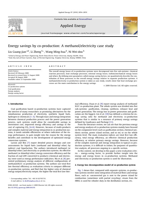
Energy savings by co-production:A methanol/electricity case studyLiu Guang-jian a,b ,Li Zheng b,*,Wang Ming-hua b ,Ni Wei-dou ba School of Energy and Power Engineering,North China Electric Power University,Beijing 102206,China bState Key Lab of Power Systems,Dept.of Thermal Engineering,Tsinghua University,Beijing 100084,Chinaa r t i c l e i n f o Article history:Received 28February 2009Received in revised form 12August 2009Accepted 20August 2009Available online 23September 2009Keywords:Co-production system Coal gasification Exergy analysisEnergy-saving factora b s t r a c tThe overall exergy losses of co-production systems were decomposed into five sub-systems:chemical reaction processes,heat exchange processes,external exergy losses,turbine/mechanical exergy losses and others.By defining new parameters called energy-saving factors,we quantitatively describe the con-tribution of these processes to the overall energy savings relative to separate production systems.A methanol/electricity co-production system is taken as case study,results show that heat exchange pro-cesses are the main contribution to the energy savings.Ó2009Elsevier Ltd.All rights reserved.1.IntroductionCoal gasification based co-production systems have captured the interest of many researchers as promising alternatives for the simultaneous production of electricity,synthetic liquid fuels,hydrogen or chemicals [1–3].Through mass and energy integration between chemical production process and the power generation process,such systems could allow for considerable savings in investment cost,improved energy efficiency and savings in the cost of capturing CO 2[4–6].However,because of multi-products and complex material and energy integration in co-production sys-tems,it needs suitable efficiencies or others indicators of the en-ergy performance,to gain insight into the reason for the energy benefits and contribute to the development of optimized energy conversion systems.Larson and Ren [7]report detailed process designs and cost assessments for liquid fuels (methanol and dimethyl ether)by indirect coal liquefaction.The authors introduced methanol (or dimethyl ether)and electricity co-production systems.An effective methanol (or dimethyl ether)energy conversion efficiency and the fraction of coal LHV converted to products (chemical and electric-ity)were used as energy performance indicators.Ma et al.[8]pre-sented preliminary energy analysis of different configurations of methanol/IGCC co-production systems.The authors use total first law thermal efficiency as evaluation criteria to compare different co-production systems,and find that the higher ratio of chemical energy output/electricity output,the higher the total first law ther-mal efficiency.Duan et al.[9]report exergy analysis of methanol/IGCC co-production plant.The whole system was divided into five sub-systems:gasification,cleanup,synthesis,exhaust heat and power generation.The exergy loss in power generation and gasifi-cation are the biggest.Lin et al.[10]has defined a criterion for en-ergy saving ratio for methanol and electricity co-production systems that is similar to a measure of primary energy savings defined by Gianfranco and Pierluigi [11].From the literature review,we can see that the previous energy and exergy analyses of co-production systems mainly have focused on the component level (such as gasification section,chemical syn-thesis section,power island section,and so on)or on the whole system level.The main evaluation indices are total first law effi-ciency,total exergy efficiency,an effective chemical production efficiency,or relative primary energy savings.However,because of the complex material and energy integration in typical co-pro-duction systems,it is difficult to isolate,for purposes of quantita-tive analysis,all processes ongoing in a specific section.In this context,we develop in this paper a new evaluation crite-ria –energy-saving factor,to provide further insight into the energy and exergy losses in co-production systems.Methanol and electricity co-production system is used for illustration.2.Exergy loss decomposition model of co-production system Fig.1shows that,compared with separate systems,co-produc-tion systems involve some integration of material flows and energy flows,such as:unconverted gas is sent to the power island for combustion (sometimes with partial recycling);steam from the HRSG is used for reboiler duty in the distillation section,etc.0306-2619/$-see front matter Ó2009Elsevier Ltd.All rights reserved.doi:10.1016/j.apenergy.2009.08.036*Corresponding author.Tel.:+861062795735.E-mail address:lz-dte@ (Z.Li).Applied Energy 87(2010)2854–2859Contents lists available at ScienceDirectApplied Energyj o ur na l h o me pa ge :w w w.e ls e v ie r.c o m/lo c a t e/ap en e rgyFor a co-production system like that shown in Fig.1(top),we can write the exergy balance equation for the system:E coalþE air1þE wtþE air2¼E mþE pþE ashþE acid-gasþE flue-gasþE N2þIr1þIr2þIr3þIr4þIr5ð1Þwhere E coal,E air1,E wt,and E air2are the exergy of input stream mate-rialflows(coal,air for air separation unit,water for coal gasification, and air for gas turbine);E m,E p,E ash,E acid-gas,Eflue-gas,and E N2are the exergy of output stream materialflows(methanol,electricity,nitro-gen vent,ash and slag,acid-gas,andflue-gas);and Ir1–Ir5are the irreversibility of gasification subsystem,methanol synthesis sub-system,product separation subsystem,gas turbine subsystem, HRSG/steam turbine subsystem.Eq.(1)can be rewritten into Eq.(4)by Eqs.(2)and(3).E ext-loss¼E N2þE ashþE acid-gasþE flue-gasÀE air1ÀE wtÀE air2ð2ÞXIr¼Ir1þIr2þIr3þIr4þIr5ð3ÞE coal¼E mþE pþXIrþE ext-lossð4ÞG.-j.Liu et al./Applied Energy87(2010)2854–28592855where we define E ext-loss to be the net external stream exergy loss;PIr is total internal exergy loss in co-production system.In order to distinguish the contribution of different types of en-ergy conversion processes ongoing in the system,PIr is decom-posed into exergy losses from (1)chemical reaction processes (including gasification reaction,methanol synthesis process,com-bustion process),(2)heat exchange processes,(3)turbine/mechan-ical exergy losses,and (4)other exergy losses (including mixing processes,separation processes,etc.).XIr ¼Ir ch þIr hx þIr ph þIr others ð5ÞFor separate power and methanol production systems,we can get similar exergy balance equations.For stand-alone methanol production system producing the same amount of methanol as in our co-production system:E coal1¼E m þIr ch-1þIr hx-1þIr ph-1þIr others-1þE ext-loss-1ð6ÞFor stand-alone power generation using IGCC producing the same amount of power as in our co-production system:E coal2¼E p þIr ch-2þIr hx-2þIr ph-2þIr others-2þE ext-loss-2ð7ÞA fuel exergy saving ratio then can be calculated:D E coal ¼E coal 0ÀE coalE coal 0¼D Ir ch E coal 0þD Ir hx E coal 0þD Ir ph E coal 0þD Ir others E coal 0þD E ext-loss E coal 0ð8ÞwhereE coal 0¼E coal1þE coal2;D Ir X ¼ðIr X À1þIr X À2ÞÀIr X ;D E ext-loss ¼ðE ext-loss-1þE ext-loss-2ÞÀE ext-loss :If we define the individual terms on the right side of Eq.(7)as:Factor 1¼D Ir ch coal 0;Factor 2¼D Ir hx coal 0;Factor 3¼D Ir ph coal 0;Factor 4¼D Ir othersE coal 0;Factor 5¼D E ext-lossE coal,then Factor 1–Factor 5represent the contributions of different types of irreversibilities to the exergy savings of co-production versus stand-alone production systems.We can name Factor 1–Factor 5the energy-saving factors of differ-ent types of process ongoing in a co-production system.Through calculation and analysis of energy-saving factors,we can describe the distribution of exergy loss in the co-production system and reveal the essence of energy saving.3.Case study of co-production system and separate production systemsFig.2shows the case study of methanol and electricity co-pro-duction system we analyze quantitatively here.Co-production plants can have different configurations than the one analyzed here and energy performance results will differ accordingly [12].The ratio of chemical to electrical product in particular can strongly affect the overall energy performance comparison.However the same approach and evaluation indices in this paper can be used to analyze any plant configuration.The clean syngas after gasification is separated into two parts:one is sent to methanol synthesis section;the other part,combined with unconverted gas from methanol synthesis and separation unit is sent to a power island to generate electricity.The system use a liquid phase methanol (LPMEOH TM )process,which uses a slurry bubble column reactor and can directly process syngas that is rich in carbon oxides (carbon monoxide and carbon dioxide),as pro-duced by oxygen-blown gasification of coal.Thus,there is no need for a water gas shift reactor to adjust syngas composition between the gasifier and the synthesis reactor.The clean syngas sent to methanol synthesis is passed once over the synthesis catalyst,with unconverted synthesis gas used to generate electricity in a gas tur-bine combined cycle.This design does not maximize liquid fuel production,but provides for a significant second revenue stream from sale of electricity.The main stream and energy integration in-volves steam recovery from gasification section and methanol syn-thesis section for integration with power island;the unconverted gas from methanol synthesis section is used as the fuel gas to gas turbine.In order to compare energy performance between different systems,we define a separate electricity generation system –IGCC based on GE quench mode gasifier (IGCC-Quench),and sep-arate methanol production system based on Lurgi gas phase methanol synthesis reactor (GPMEOH).The detail simulation re-sults can ben seen in Ref.[13].The coal compositionalanalysisTable 1Compositional characteristics of Yanzhou coal.Proximate analysis (wt.%,as-received)Ultimate analysis (wt.%,dry)Moisture 5.81ASH 7.53Fixed carbon 49.85Carbon 73.64Volatile matter 37.24Hydrogen 5.24ASH7.09Nitrogen 1.13HHV (kJ/kg,dry)28,526Sulfur 2.63Oxygen9.832856G.-j.Liu et al./Applied Energy 87(2010)2854–2859and the key process operation parameters are shown in Tables1 and2.4.Results and discussionTable3shows a comparison of the exergy efficiencies and exer-gy loss distribution between the separated systems and the co-pro-duction system.The total exergy efficiency of co-production system is47%, which is in between that of the IGCC system(39%)and the methanol production system(54%).The exergy losses of gasification and combustion are the big-gest in three systems,accounting for16%in stand-alonemethanol system to30%in IGCC system of input coal exergy, the reason is high irreversiblities in heat transfer between product molecules and reactant molecules and chemical reactions(gasification and combustion)of gasifier and gas turbine combustor(or boiler in stand-alone methanol sys-tem)units,which are in principle avoidable.The second biggest losses are heat exchange processes, accounting for10%in co-production system to12%in sepa-rated systems of input coal exergy.If the output of electricity and methanol is the same for separate and co-production systems,the total fuel exergy saving ratio is 7.1%(see Fig.3).Chemical reaction processes and heat exchange processes are the biggest contributors.In chemical reaction pro-cesses,the energy-saving factor is2.6%,accounting for36.4%of the total fuel saving ratio;in heat exchange processes,the en-ergy-saving factor is2.5%,accounting for35.2%of the total fuel saving ratio.Other energy-saving factors are relatively small,less than1.0%.Therefore the main energy saving sources is from chem-ical reaction and heat exchange processes.Further analysis of these two sub-systems is highlight in the next section.Table2Reference operating parameters of the co-production systems.Section Technology Parameter(unit)ValueGasificationprocess Entrained-flow gasifier(GE-Quench)Pressure(MPa) 4.0/7.0*Gasificationtemperature(°C)1300Slurry solid density66.5%Carbon conversionratio98%Methanolsynthesisprocess Gas phase methanolsynthesis(stand-alonesystem)Pressure(MPa) 5.0Temperature(°C)250Recycle ratio 4.5 Liquid phase methanolsynthesis(co-production system)Pressure(MPa) 6.5Temperature(°C)250Recycle ratio0Power island Gas turbine(based onSiemens V94.3)Pressure ratio16.1 Turbine inlettemperature(°C)1340Exhaust gastemperature(°C)576HRSG&steam cycle (from literature[8])Pinch temperature(°C)15 Approachtemperature(°C)15 Exhaustflue-gas temperature(°C)110*For IGCC,the pressure is4.0MPa;for methanol production and co-productionsystem,it is7.0MPa.Table3Exergy losses and exergy efficiency comparison between separated system and co-production system when T o=298.15K and P o=101.3kPa.Stand-alone power(IGCC)Stand-alone methanol(GPMEOH)Co-productionkJ/kg-coal Ratio(%)kJ/kg-coal Ratio(%)kJ/kg-coal Ratio(%) Coal input29,051100.029,051100.029,051100.0Exergy lossesChemical reactionGasification402213.8362312.5392213.5 Combustion485016.7919 3.2337211.6 Shift reaction––1740.60.000.0 Methanol synthesis––355 1.21430.5 External exergyflows*1738 6.01769 6.11744 6.0 Heat exchange336811.6354511.928899.9 Air separation unit**847 2.91393 4.8879 3.0 Turbine/mechanical25248.71016 3.520217.0 Others414 1.4567 2.0403 1.4Sum17,76361.113,26845.715,37152.9OutputMethanol––15,78354.3540918.6Net electricity11,28838.9––827028.5 Total exergy output11,28838.915,78354.313,67947.1*This is the net exergy of streamflows into and out of the system.**The air separation unit is not simulated but taken as a separate process for simplification.G.-j.Liu et al./Applied Energy87(2010)2854–285928574.1.Energy-saving analysis of reaction sub-systemsThe chemical reaction processes in co-production system in-cludes four parts:coal gasification,water–gas shift reaction(shift reaction),methanol synthesis,and combustion.For the gasification process,the small benefit in exergy effi-ciency is due to the higher gasification pressure used in the co-production system compared with the low gasifier pres-sure in the IGCC[14].No shift reaction is needed to change the syngas H2/CO ratio in the co-production system,but shift reaction process is a relatively efficient process,1so the exergy gain due to lack of shift reaction is small(about0.19%).For methanol synthesis process,it is interesting that the exergy loss of co-production system is higher than that of the separate processes.The reason is that the CO conversion in the LPMEOH process is only20.3%,while it is97%for GPMEOH process due to recycling of unconverted syngas.Assuming the same methanol output,because of heat exchange between the unconverted syngas and products in the methanol synthesis reactor,the exergy loss per kg MeOH of the co-production system is larger than that of the stand-alone methanol system.For combustion process,the energy-saving factor is1.59%, second only to heat exchange processes.But this does not mean the exergy loss in combustion process can be decreased,it is still the second biggest exergy loss source in co-production system,see Table3.It can be explained that due to the heat integration between power island and chem-ical production process,the power output from steam tur-bine is relatively larger than that without heat integration.We use the power ratio of steam turbine to gas turbine(c) to reflect the effect of heat integration:the value of c in co-production system is0.79,while it is only0.65for weighted average of separate systems(the value of c in IGCC plant is about0.6[15]and it is1for stand-alone methanol system).This means that if total power output is the same for the co-production system and separate systems,the GT power output in co-production system is smaller than that of the separate systems,leading to less exergy loss in com-bustion process.4.2.Energy-saving analysis of heat exchange processThe heat exchange processes are characterized by the biggest energy-saving factor.The different heat exchange processes can be divided into two types.One is essential heat exchangers which are required to fulfill energy conversion tasks,such as waste heat boilers,the gasifier quench process,and heat loss in condenser cooling system.The other is the heat exchangers which are used to reduce the additional exergy losses with unmatched heat ex-change processes,such as the methanol synthesis reaction heat can be used to generate saturated steam that can be superheated in the gas turbine combined cycle section of the co-production plant;or the saturated steam can be used for methanol distillation unit at the stand-alone methanol production plant.With the same products output,Fig.4shows the exergy loss ratio of co-production and separate systems.Here the exergy loss ratio means the ratio of exergy losses of different heat exchange processes to coal exergy input.As can be seen,the exergy loss ratio of the second class of heat exchange processes decreases by1.34%, which accounts for54%of the total difference in exergy loss ratio of heat exchange processes between co-production and stand-alone systems.The main reason is that high heat integration potential in co-production system than that of stand-alone systems,such as no synthesis or shift reaction heat to be recovered in stand-alone power system and less high-temperature heat available(from combustion of the purge gas thatfire the power island)in stand-alone methanol system,which can be revealed by the ratio of the steam turbine to gas turbine output in the co-production and stand-alone systems.1In stand-alone methanol system,about55%coal derived syngas is needed to besent to shift reactor to adjust the H2/CO ratio from0.62to2.38by the water shiftreaction:CO+H2O vap?CO2+H2+44.477MJ/Mol CO.(i)The two moles on the lefthand side(CO+H2O vap)exhibit an exergy of287.14MJ,while the exergy of the twomoles on the right hand side(CO2+H2)is258.63MJ.(ii)The heat developed in thereaction—at the reference temperature of25°C,44.477MJ/Mol CO(assume shiftreactor is operated at constant temperature350°C,the exergy of reaction heat isabout23MJ/Mol CO)—can be recovered in the steam cycle.2858G.-j.Liu et al./Applied Energy87(2010)2854–28595.Summary and conclusions(1)In our analysis,exergy loss in co-production systems isdivided according to different processes:chemical reaction processes,heat exchange processes,external exergyflows losses,turbine/mechanical exergy losses,and other exergy losses.We defined the energy-saving factors,which can be used for quantitative description of the effects of different processes to the total energy saving ratio.(2)For the case study of methanol and electricity co-productionsystem we analyzed,the total exergy efficiency is47%,which unsurprisingly is in between that of IGCC system(39%)and stand-alone methanol production system(54%).The exergy losses of gasification and combustion are the biggest in three systems,because of high irreversiblities in internal thermal energy exchange and chemical reactions(gasification and combustion)of gasifier and gas turbine combustor(or boiler in stand-alone methanol system)units,which are in princi-ple avoidable.(3)With the same product outputs,the total coal exergy savingratio of the case study co-production system is7.1%.The big-gest energy-saving factor is associated with heat exchange processes,accounting for35%of the total coal exergy sav-ings;the next is the energy-saving factor of combustion pro-cess,accounting for22%of the total coal exergy saving.The ratio of steam turbine output to gas turbine output in co-production system is0.79,about20%higher than for an IGCC system,which reflects the heat integration of the whole system.(4)Co-production plants can have different configurations thanthe one analyzed here will have different energy perfor-mance results.Particularly,the ratio of chemical product and electricity can strongly affect the overall energy perfor-mance comparison.However the same approach and evalu-ation indexes in this paper can be used for analysis different plant configuration.AcknowledgementThis work is supported by the special fund of the national prior-ity basic research program(No.2005CB221207).We gratefully acknowledge Dr.Eric rson at Princeton University for instruc-tion on the editorial organization of the paper and discussion on the energy saving analysis section.References[1]Ni Wei-dou,Li Zheng.The ultra-clean utilization of coal-polygenerationsystem.Energy Conserv Environ Protect2001;5:16–21[in Chinese].[2]Hetland Jens,Zheng Li,Shisen Xu.How polygeneration schemes may developunder an advanced clean fossil fuel strategy under a joint sino-European initiative.Appl Energy2009;86:219–29.[3]Yamashita Kei,Barreto Leonardo.Energyplexes for the21st century:coalgasification for co-producing hydrogen,electricity and liquid fuels.Energy 2005;30:2453–73.[4]Lin Ru-mou,Jin Hong-guang,Gao Lin.The integration and optimizationmechanism of co-production system.J Eng Therm Energy Power 2006;21(4):331–7[in Chinese].[5]Jin Hong-guang,Gao Lin,Zheng Dan-xing,et al.Investigation of coal-based co-production system for power and chemical production.J Eng Thermophys 2001;22(4):397–400[in Chinese].[6]Wang Zhifang,Zheng Danxing,Jin Hongguang.Energy integration of acetyleneand power polygeneration byflowrate-exergy diagram.Appl Energy 2009;86(3):372–9.[7]Larson ED,Ren Ting-jin.Synthetic fuel production by indirect coal liquefaction.Energy Sustain Dev2003;VII(4):79–102.[8]Ma Lin-wei,Ni Wei-dou,Li Zheng,Ren Ting-jin.Analysis of the co-productionsystem of methanol and electricity based on coal gasification.Power Eng 2004;24(3):451–6[1,in Chinese].[9]Duan Yuanyuan,Zhang Jin,Shi Lin,et al.Exergy analysis of methanol-IGCCpolygeneration technology based on coal gasification.Tsinghua Sci Technol 2002;7(2):190–3.[10]Lin Gao,Hongguang Jin,Zelong Liu,Danxing Zheng.Exergy analysis of coal-based co-production system for power and chemical production.Energy 2004;29:2359–71.[11]Gianfranco Chicco,Pierluigi Mancarella.A unified model for energy andenvironmental performance assessment of natural gas-fueled poly-generation systems.Energy Convers Manage2008;49:2069–77.[12]Gao Lin.Investigation of coal-based polygeneration systems for production ofpower and liquid fuel.Ph.D.Dissertation.Beijing:Institute of Engineering Thermophysics,Chinese Academy of Sciences;2005[in Chinese].[13]Liu Guangjian.Study on energy saving performance analysis andcomprehensive evaluation method of polygeneration system.Ph.D.Dissertation.Tsinghua University;2007[in Chinese].[14]Prins MJ,Ptasinski KJ.Energy and exergy analyses of the oxidation andgasification of carbon.Energy2005(30):982–1002.[15]National Energy Technology Laboratory.Cost and performance baseline forfossil energy plants.Bituminous coal and natural gas to electricityfinal report, vol.1.DOE/NETL-2007/1281;May2007.G.-j.Liu et al./Applied Energy87(2010)2854–28592859。
煤化工英语
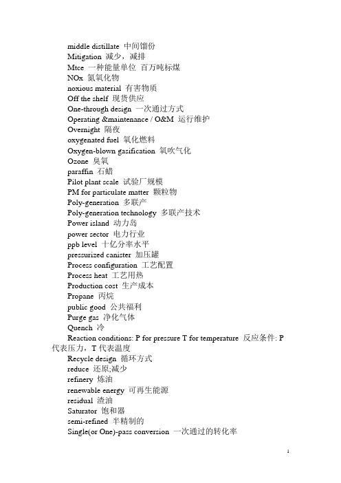
middle distillate 中间馏份Mitigation 减少,减排Mtce 一种能量单位百万吨标煤NOx 氮氧化物noxious material 有害物质Off the shelf 现货供应One-through design 一次通过方式Operating &maintenance / O&M 运行维护Overnight 隔夜oxygenated fuel 氧化燃料Oxygen-blown gasification 氧吹气化Ozone 臭氧paraffin 石蜡Pilot plant scale 试验厂规模PM for particulate matter 颗粒物Poly-generation 多联产Poly-generation technology 多联产技术Power island 动力岛power sector 电力行业ppb level 十亿分率水平pressurized canister 加压罐Process configuration 工艺配置Process heat 工艺用热Production cost 生产成本Propane 丙烷public good 公共福利Purge gas 净化气体Quench 冷Reaction conditions: P for pressure T for temperature 反应条件: P 代表压力,T代表温度Recycle design 循环方式reduce 还原;减少refinery 炼油renewable energy 可再生能源residual 渣油Saturator 饱和器semi-refined 半精制的Single(or One)-pass conversion 一次通过的转化率Slurry 浆SO2 二氧化硫social cost 社会成本Soot 烟灰Spark-ignition engine 火花引燃式发动机Stand-alone 单独的Streamline 简化使有效率Sulfur 硫Syncrude 合成原油Syngas or synthesis gas 合成气Syngas park 合成气园Synthesis 合成Synthesis conversion 合成转化率synthesis reactor 合成反应器Synthetic fuel 合成燃料TFESTTI for Technical Infrastructure 技术基础设施toxic metal 有毒金属物Unreacted 未反应的USDOE 美国能源部Vapor pressure 蒸汽压Vent 排放Water gas shift / WGS 水煤气变换aerosol propellant气溶胶喷射剂aftertreatment 后处理ammonia 氨Annual capacity factor年均利用率Annual capital charge rate 年均资本回收率aromatic 芳族化合物As-received收到基(煤)atmospheric pollution 大气污染Auto-ignition temperature自燃温度,自燃点biodiesel 生物柴油Biomass 生物质Blend 混和Boiling point沸点Capacity 容量capital intensity 资本强度Carbon emission 二氧化碳排放Carbon sequestration 埋存碳(二氧化碳)Carbon(CO2) capture and storage 回收并储存碳(二氧化碳) Catalyst 催化剂CBM 煤层气C-C bond 碳-碳化学键Cetane (number) 十六烷值Chemical feedstock 化工原料Chemicals 化工产品CNG 压缩天然气CO2 二氧化碳Coal (syngas) polygeneration 煤气化多联产Coal derived 煤基Coal mining 采煤Coal slurry 水煤浆coal steam-electric plant 火电厂Coalsteam plant with FGD 火力发电厂烟气脱硫Co-capture / Co-storage (或CC+CS) 联合回收/联合存储cold start 冷态启动Commercial scale 大规模、工业规模Compression-ignition engine or CIE 压燃式发动机Cool Water demonstration 冷水示范电厂Cooling water 冷却水coproduct 副产物Co-production 联产Cost estimate 成本估计Cracking catalyst 裂化催化剂Crude oil 原油DCL / Direct coal liquefaction 煤直接液化Dehydration of methanol 甲醇脱水反应Density 密度Desulfurization 脱硫diesel engine 柴油发动机Dimethyl ether or DME CH3OCH3 二甲醚Direct liquefaction technology 直接液化技术Disengagement zone 分离区electricity or power generation 发电Energy Mix 能源构成Equilibrium limit 化学平衡限制Equivalent 等价物ER for emission rate 排放率Externality 外部因素Financial cost 经济成本,财务成本Fischer-Tropsch synthesis or F-T 费脱合成Flammability limits 可燃极限FTL for F-T liquids 费脱合成液体燃料Fuel cycle 燃料循环Gasification 气化Gasoline 汽油Gas-phase reactor 气相反应器GHG emissions mitigation 减排温室气体Global warming 全球变暖Greenhouse gas or GHG 温室气体Grid 电网Grind 碾碎GTL for Gas To Liquids 气变油H2/CO ratio or H/C ratio 合成气中氢气/一氧化碳含量比,氢碳比H2S 硫化氢HC for hydrocarbon 烃,碳氢化合物HC fuel 烃类燃料Health cost 健康损害Heating 采暖heavy-duty 重型的Hybrid-electric 混合电能hydrogenation 加氢作用ICL for Indirect Coal Liquefaction 煤间接液化IGCC plant 整体煤气化联合循环电厂Installed capital cost 建设投资成本intellectual property 知识产权JV for joint venture 合资企业Life cycle 全生命周期Liquefaction 液化Liquid-phase 液相Liquid-phase reactor 液相反应器Location factor 区域因子LowEff Low efficiencyLower heat value 低位热值LPG 液化石油气Lube oil 润滑油methane 甲烷Methanol or MeOH CH3OH 甲醇middle distillate 中间馏份Mitigation 减少,减排Mtce 一种能量单位百万吨标煤NOx 氮氧化物noxious material 有害物质Off the shelf 现货供应One-through design 一次通过方式Operating &maintenance / O&M 运行维护Overnight 隔夜oxygenated fuel 氧化燃料Oxygen-blown gasification 氧吹气化Ozone 臭氧paraffin 石蜡Pilot plant scale 试验厂规模PM for particulate matter 颗粒物Poly-generation 多联产Poly-generation technology 多联产技术Power island 动力岛power sector 电力行业ppb level 十亿分率水平pressurized canister 加压罐Process configuration 工艺配置Process heat 工艺用热Production cost 生产成本Propane 丙烷public good 公共福利Purge gas 净化气体Quench 激冷Reaction conditions: P for pressure Tfor temperature 反应条件: P代表压力,T代表温度Recycle design 循环方式reduce 还原;减少refinery 炼油renewable energy 可再生能源residual 渣油Saturator 饱和器semi-refined 半精制的Single(or One)-pass conversion 一次通过的转化率Slurry 浆SO2 二氧化硫social cost 社会成本Soot 烟灰Spark-ignition engine 火花引燃式发动机Stand-alone 单独的Streamline 简化使有效率Sulfur 硫Syncrude 合成原油Syngas or synthesis gas 合成气Syngas park 合成气园Synthesis 合成Synthesis conversion 合成转化率synthesis reactor 合成反应器Synthetic fuel 合成燃料TI for Technical Infrastructure 技术基础设施toxic metal 有毒金属物Unreacted 未反应的USDOE 美国能源部Vapor pressure 蒸汽压Vent 排放Water gas shift / WGS 水煤气变换aerosol propellant 气溶胶喷射剂aftertreatment 后处理ammonia 氨Annual capacity factor 年均利用率Annual capital charge rate 年均资本回收率aromatic 芳族化合物As-received 收到基(煤)atmospheric pollution 大气污染Auto-ignition temperature 自燃温度,自燃点biodiesel 生物柴油Biomass 生物质Blend 混和Boiling point 沸点Capacity 容量capital intensity 资本强度Carbon balance 碳平衡Carbon emission 二氧化碳排放Carbon sequestration 埋存碳(二氧化碳)Carbon(CO2) capture and storage 回收并储存碳(二氧化碳) Catalyst 催化剂CBM 煤层气C-C bond 碳-碳化学键Cetane (number) 十六烷值Chemical feedstock 化工原料Chemicals 化工产品CNG 压缩天然气CO2 二氧化碳Coal (syngas) polygeneration 煤气化多联产Coal derived 煤基Coal mining 采煤Coal slurry 水煤浆coal steam-electric plant 火电厂Coalsteam plant with FGD 火力发电厂烟气脱硫Co-capture / Co-storage (或CC+CS) 联合回收/联合存储cold start 冷态启动Commercial scale 大规模、工业规模Compression-ignition engine or CIE 压燃式发动机Cool Water demonstration 冷水示范电厂Cooling water 冷却水coproduct 副产物Co-production 联产Cost estimate 成本估计Cracking catalyst 裂化催化剂Crude oil 原油DCL / Direct coal liquefaction 煤直接液化Dehydration of methanol 甲醇脱水反应Density 密度Desulfurization 脱硫diesel engine 柴油发动机Dimethyl ether or DME CH3OCH3 二甲醚Direct liquefaction technology 直接液化技术Disengagement zone 分离区electricity or power generation 发电Energy balance 能量平衡Energy Mix 能源构成Equilibrium limit 化学平衡限制Equivalent 等价物ER for emission rate 排放率Externality 外部因素Financial cost 经济成本,财务成本Fischer-Tropsch synthesis or F-T 费脱合成Flammability limits 可燃极限FTL for F-T liquids 费脱合成液体燃料Fuel cycle 燃料循环Gasification 气化Gasoline 汽油Gas-phase reactor 气相反应器GHG emissions mitigation 减排温室气体Global warming 全球变暖Greenhouse gas or GHG 温室气体Grid 电网Grind 碾碎GTL for Gas To Liquids 气变油H2/CO ratio or H/C ratio 合成气中氢气/一氧化碳含量比,氢碳比H2S 硫化氢HC for hydrocarbon 烃,碳氢化合物HC fuel 烃类燃料Health cost 健康损害Heating 采暖heavy-duty 重型的Hybrid-electric 混合电能hydrogenation 加氢作用ICL for Indirect Coal Liquefaction 煤间接液化IGCC plant 整体煤气化联合循环电厂Installed capital cost 建设投资成本intellectual property 知识产权JV for joint venture 合资企业Life cycle 全生命周期Liquefaction 液化Liquid-phase 液相Liquid-phase reactor 液相反应器Location factor 区域因子LowEff Low efficiencyLower heat value 低位热值LPG 液化石油气Lube oil 润滑油methane 甲烷Methanol or MeOH CH3OH 甲醇middle distillate 中间馏份Mitigation 减少,减排Mtce 一种能量单位百万吨标煤NOx 氮氧化物noxious material 有害物质Off the shelf 现货供应One-through design 一次通过方式Operating &maintenance / O&M 运行维护Overnight 隔夜oxygenated fuel 氧化燃料Oxygen-blown gasification 氧吹气化Ozone 臭氧paraffin 石蜡Pilot plant scale 试验厂规模PM for particulate matter 颗粒物Poly-generation 多联产Poly-generation technology 多联产技术Power island 动力岛power sector 电力行业ppb level 十亿分率水平pressurized canister 加压罐Process configuration 工艺配置Process heat 工艺用热Production cost 生产成本Propane 丙烷public good 公共福利Purge gas 净化气体Quench 冷Recycle design 循环方式reduce 还原;减少refinery 炼油renewable energy 可再生能源residual 渣油Saturator 饱和器semi-refined 半精制的Single(or One)-pass conversion 一次通过的转化率Slurry 浆SO2 二氧化硫social cost 社会成本Soot 烟灰Spark-ignition engine 火花引燃式发动机Stand-alone 单独的Streamline 简化使有效率Sulfur 硫Syncrude 合成原油Syngas or synthesis gas 合成气Syngas park 合成气园Synthesis 合成Synthesis conversion 合成转化率synthesis reactor 合成反应器Synthetic fuel 合成燃料TFESTTI for Technical Infrastructure 技术基础设施toxic metal 有毒金属物Unreacted 未反应的USDOE 美国能源部Vapor pressure 蒸汽压Vent 排放Water gas shift / WGS 水煤气变换China Coal Right Element For Chemical FirmsFor years China has been a magnet for the chemicals industry, attracting European and American companies with its cheap production costs and growing market.Now China has another attraction for the energy-intense chemical industry: vast supplies of coal that can replace oil and natural gas as raw materials for chemical production.In the last two years, China has built nearly 20 plants that convert coal into a gas that can be used to make such things as plastic and pharmaceuticals, according to the Gasification Technologies Council, an industry trade group. The new plants draw on technology developed by companies such as General Electric Co. and Royal Dutch Shell PLC. Now, Western chemical firms are getting in on the action. Celanese Corp. opened a plant this year that uses coal-based feedstock to make a chemical used in paints and food sweeteners. Dow Chemical Co. has partnered with Chinese energy company Shenhua Group Corp. to study a project to convert coal into plastics. Mining company Anglo American PLC is also looking at a coal-to-chemicals project. Suppliers to the chemical industry, such as Praxair Inc., are vying to open accounts with the new coal-to-chemical plants.'Coal to chemicals is an opportunity that's literally exploding [in China] right now,' says Timothy Vail, chief executive and president of Synthesis Energy Systems Inc., a company that builds coal-gasification plants. Launching their own coal-to-chemicals projects in China represents one way Western companies are fighting to keep their competitive edge. In the past decade, chemicals makers based in Europe and North America have lost market share to their counterparts in Asia, where demand for chemicals is rapidly growing.China's government, meanwhile, has orchestrated the buildup of the coal-to-chemicals industry in an effort to reduce the nation's growing dependence on imported natural gas. Using China's vast coal deposits to make chemicals and plastics provides a more reliable source of raw materials that can feed the expansion of China's main economic growth engine, its manufacturing sector. The new plants also replace older, soot-belching chemical factories that have earned the government a bad reputation for the pollution they create in Chinese cities.Gasification technology, which uses high temperatures and pressure to break the molecular bonds in coal to produce gases that can be recombined into a variety of fuels and chemicals, has existed for more than a century. Germany gasified coal to fuel its planes during World War II. China has made fertilizers through gasification for decades. But there had been little incentive for the global chemical industry to gasify coal until prices began soaring for natural gas and oil.North America has its own huge reserves of coal, sparking interest in gasification plants in that continent as well. But development has been slowed by concerns that the projects would contribute to growing emissions of the gases that cause global warming. Among fossil fuels, coal emits an especially large amount of carbon dioxide when being burned, and man-made carbon dioxide is one of the most prevalent gases that human activities are contributing to earth's rising temperatures. Gasifying coal to produce chemicals emits less carbon dioxide than does burning coal as fuel, but the process still ejects more carbon dioxide into the atmosphere than using natural gas would produce, says Eric Larson, a research engineer at the Princeton Environmental Institute.The U.S. government doesn't yet limit nationwide the amount of global-warming emissions industry can release into the air. But the future prospect of such rules, along with coal's dirty reputation, has kept coal gasification from catching on in the U.S. on the same scale as it has in China, analysts say. 'There is a stigma about coal because of its historical environmental and safety concerns,' says Edward Glatzer, director of technology at Nexant Inc., a San Francisco-based consulting firm.Some of the Western companies planning to jump into the sector in China, including Dow Chemical, are considering ways to offset or store the global-warming emissions their projects will generate. One possibility -- a process that would inject carbon dioxide deep underground for storage -- is a largely untested technology that is likely to be very expensive. In the meantime, gasification projects are getting speedily green-lighted in China without concern over emissions.China is poised to surpass the U.S. as the No. 1 emitter of greenhouse gases in the world. Studies show that about one-fourth of China's global-warming emissions are released in the process of making the tennis shoes, toys, computers, shirts and other products that the country exports abroad.While the Chinese government agrees on the need to reduce carbon emissions, it prefers to achieve that through increased energy efficiency and by using more alternative energy. It has no plans to cap carbon emissions because it believes such a move would limit economic growth. Government officials have smoothed the way for gasification projects by fast-tracking permits and helping companies to secure capital, industry executives say. 'In anywhere between 24 to 32 months they have [plants] built and operating,' says John Lavelle, general manager of GE Energy's gasification business. 'It's pretty remarkable.'Cheap labor and minimal regulations mean coal-gasification plants in China can be built for about two-thirds to one-half the cost of a project in the U.S. or Europe. Coal-to-chemical plants built in the last two years have expanded Chinese capacity by 1,575 cubic feet of gas a day that can be used as chemical feedstocks, according to the Coal Gasification Council. The plants slated for construction in the next four years will double that capacity.Western companies involved in China's coal-to-chemical industry argue that coal gasification has the potential to be environmentally friendly. Because the gasification process separates out carbon dioxide, the global-warming gas can be more easily captured and stored once an affordable technology is developed. Dow, for example, says it is studying ways to sequester carbon dioxide -- or to offset its environmental impact by reducing emissions elsewhere through projects such as planting carbon-dioxide-consuming trees.Celanese says it is committed to controlling greenhouse-gas emissions in all its operations, reducing them by 30% from 2005 to 2010. 'Reducing emissions means you are more efficient,' says David Weidman, the company's CEO and also a member of the board for environmental group the Conservation Fund.Chinese companies aren't sweating the issue, say analysts at the China Petroleum and Chemical Industry Association. Only China's two biggest oil and chemical firms, the state-owned giant China Petroleum & Chemical Corp., known as Sinopec, and China National Petroleum Corp., parent of the listed PetroChina, are studying how to store carbon emissions.多年来中国对化学工业来说一直是一块“磁石”,其低廉的生产成本和不断扩大的市场吸引了众多欧美公司。
化学化工专业英语第十三课
• The first process step is gasification, which(引导定语从 句) converts the coal into a ‘‘synthesis gas’’ (or syngas) c(CoOnt)a(in是ingcopnritmaianrinilyg的hy现dr在og分en词(H短2语) a作ndsycnatrhbeosnismgoanso的xi定de 语). A variety of gasifier designs are in commercial operation worldwide using coal or other dirty, low-value feedstocks (e.g., petroleum coke generated at refineries). Here we have chosen to consider a design based on the technology of Chevron/Texaco. This design uses partial oxidation of the coal in oxygen (generated in a dedicated air separation unit) to provide the requisite heat to drive the gasification reactions. The coal is fed into the reactor in a water slurry, which(引导定语从句) has two important implications. Feeding can be done into a vessel operating at relatively high pressures (75 bar in plant configurations considered in this paper), which(引 导定语从句) provide thermodynamic and cost benefits to the overall process, and the additional hydrogen (in the slurry water) promotes a larger H2 fraction in the syngas compared to a dry-feed gasifier design.
矿物加工专业英语
1 矿物(minerals)Minerals definition: Minerals by definition are natural inorganic substances possessing definite chemical compositions and atomic structures.矿物的定义:具有稳定的化学成分、晶体结构的天然无机化合物。
Mineral types: native and metallic form, oxides, sulphides, carbonates, silicates and chlorides.矿物的种类:主要按化学成分划分:单质矿物、氧化物、硫化物、碳酸盐、硅酸盐、卤化物等。
Isomorphism: substitution of atoms within the crystal structure by similar atoms takes place without affecting the atomic structure.类质同象:矿物晶体中的原子被类似原子取代而不改变矿物晶体结构的现象。
例如:铁橄榄石—镁橄榄石。
Polymorphism: different minerals have the same chemical composition, but markedly different physical properties due to a difference in atomic structure.同质多象:矿物的化学成分相同,但晶体结构和物理化学性质不同的现象。
例如:金刚石、石墨。
Rocks: Rocks consist of a variety of minerals and form larg e parts of the earth’s crust. Granite, for instance, which is the most abundant igneous rock, is composed of three main mineral constituents, feldspar, quartz, and mica.岩石:由一种或多种矿物组成的天然集合体,例如:花岗岩主要由石英、长石、云母以不同比例组成。
中石化职称考试英语复习题

英译汉There is an increase in damand for all kinds of consumer goods in every part of our coun-trry. 译为:我国各地对各种消费品的需求量正大大增加。
We also realized the growing need and necessity to industrialize certain sectoymned to pur-sue it .译为我们也认识到越来越需要使某些经济部门工业化。
They are deeply convinced of the ourrectness of this pocicy and firmly determined to pur-sue it. 译为:我们深信这一政策是正确的,并有坚定的决心继续奉行这一政策。
Weseek a deep-rooted understanding through the multiplication of our economic, cultur-al,scientific , technical and human ties.译为:我们要通过加强我们之间的经济、文化、科学、技术和人员等方面的交流来加深彼此的了解。
Rockets heve found applications for zhe exploration of the universe译为:火箭已经用来探索宇宙。
If we were ignorant of the structure of the atom ,it would be impossible for us to study nuclear physics 译为:如果我们不知道原子的结构,我们我们就不可能研究核子物理学。
Electronic control techniques can be designed to take full advantage of quick response in-herent in a gas turbine proulsion system译为:电子控制技术可以充分地利用燃气轮机推进系统固有的反应快的优点。
- 1、下载文档前请自行甄别文档内容的完整性,平台不提供额外的编辑、内容补充、找答案等附加服务。
- 2、"仅部分预览"的文档,不可在线预览部分如存在完整性等问题,可反馈申请退款(可完整预览的文档不适用该条件!)。
- 3、如文档侵犯您的权益,请联系客服反馈,我们会尽快为您处理(人工客服工作时间:9:00-18:30)。
Synthetic fuel production byindirect coal liquefactionEric D. LarsonPrinceton Environmental Institute, Princeton UniversityGuyot Hall, Washington Road, Princeton, NJ 08544-1003, USAE-mail: elarson@Ren TingjinDepartment of Thermal Engineering, Tsinghua University, 100084 Beijing, ChinaThis paper reports detailed process designs and cost assessments for production of clean liquid fuels (methanol and dimethyl ether) by indirect coal liquefaction (ICL). Gasification of coal pro-duces a synthesis gas that can be converted to liquid fuel by synthesis over appropriate catalysts. Recycling of unconverted synthesis gas back to the synthesis reactor enables a larger fraction of the coal energy to be converted to liquid fuel. Passing synthesis gas once over the synthesis catalyst, with unconverted synthesis gas used to generate electricity in a gas turbine combined cycle, leads to less liquid fuel production, but provides for a significant second revenue stream from sale of electricity. Recently-developed liquid-phase synthesis reactors are especially attractive for ‘‘once-through’’ processing. Both ‘‘recycle’’ and ‘‘once-through’’ plant configurations are evaluated in this paper. Because synthesis catalysts are poisoned by sulfur, essentially all sulfur must be re-moved upstream. Upstream removal of CO2 from the synthesis gas is also desirable to maximize synthesis productivity, and it provides an opportunity for partial decarbonization of the process, whereby the removed CO2 can be captured for underground storage. The analysis here suggests that co-capture and co-storage of CO2 and H2S (if this is proven technically feasible) could have important favorable impacts in some cases on liquid fuel production costs. Furthermore, the life-cycle CO2 emissions from production and use of fuels made by ICL would be lower than with production and use of petroleum-derived transportation fuels. If CO2 is not captured at ICL fa-cilities, lifecycle CO2 emissions to the atmosphere would be considerably higher than lifecycle emissions with petroleum-derived fuels.1. IntroductionFor China, with abundant domestic coal resources but lim-ited oil and gas resources, the conversion of coal into liquid fuels offers an alternative to importing petroleum or gas-based transportation fuels. Two routes to liquid fu-els from coal include direct coal liquefaction (DCL) and indirect coal liquefaction (ICL). DCL, the production of a synthetic crude oil product by direct contact of coal with an appropriate catalyst in the presence of added hy-drogen at elevated temperature, is discussed in a compan-ion paper [Williams and Larson, 2003]. ICL is the production of fuels with an intermediate step of synthesis gas production by coal gasification. The principal con-stituents of ‘‘syngas’’ are carbon monoxide and hydrogen, which can be processed chemically into a variety of dif-ferent fuels.Fuels that can be made by ICL include methanol (CH3OH), dimethyl ether (CH3OCH3), Fischer-Tropsch diesel- or gasoline-like fuels, and hydrogen (H2). The availability of CO and H2 as molecular building-blocks at an ICL facility also provides opportunities for produc-tion of chemicals. Commercial application of ICL for fuel production today exists in South Africa (for Fischer-Tropsch fuels). Also, the US Department of Energy an-nounced its financial backing for a $ 612 million project early this year to demonstrate advanced Fischer-Tropsch fuel production by ICL at a site in Pennsylvania[1]. In China, the production of methanol (primarily for use as chemical feedstock) by ICL processes is commercially es-tablished[2]. China has an estimated 10 to 15 modern coal gasification facilities in operation to make hydrogen for ammonia production. Also, there is considerable interest in China (especially Shanxi Province) in the use of metha-nol as a vehicle fuel [Niu, 2003]. There is also interest in pursuing ICL to produce dimethyl ether (DME) from coal: in 2002, China’s State Development Planning Com-mission approved plans for the first large-scale coal-to-DME project, to be located in Ningxia Province. Dimethyl ether is a less familiar fuel option than metha-nol. It is used today exclusively as a chemical feedstock and aerosol propellant (e.g., in hair-sprays). DME is a potential premium fuel for compression ignition (diesel) engines because of its high cetane rating and because it burns without sooting since it contains no carbon-carbonArticlesReproduced with permission from Energy for Sustainable Developmentbonds, and NO x emissions are lower than when using con-ventional diesel fuel [Fleisch et al., 1997; Zhou et al.,2000; Fleisch et al., 1995; Sorenson and Mikkelsen,1995]. DME can be reformed into hydrogen at least as easily as methanol, and thus is potentially suitable for fu-ture use as a hydrogen source for stationary or vehicle fuel cells. One drawback of DME as a vehicle fuel is the need for modest pressurization to store it as a liquid (Table 1). DME can also be used as an LPG substitute in do-mestic applications, e.g., cooking, where it burns with a clean blue flame over a wide range of air/fuel ratios [Fleisch et al., 1995; ICC, 2003]. DME is relatively inert,non-corrosive, non-carcinogenic, almost non-toxic, and does not form peroxides by prolonged exposure to air [Hansen et al., 1995].DME is produced globally today at a rate of about 150,000 tonnes (t) per year in small-scale facilities by de-hydration of MeOH [Naqvi, 2002]. Technologies are available for converting syngas from natural gas or coal directly into DME (rather than with intermediate methanol production), but the small size of today’s DME markets has not justified building direct conversion facilities,which require relatively large scale to achieve attractive economics. The Chinese Ningxia coal-to-DME project has a planned output capacity of 830,000 t/yr DME using a direct conversion process, and the principal intended application is as a household cooking fuel [Lucas, 2002].In this paper, we present detailed process designs and performance estimates for production of DME from coal,together with cost analysis. Since there are many similari-ties to methanol production, which is more widely under-stood, we include self-consistent analyses of methanol from coal for reference.2. Basic process configurations for indirect coal liquefactionFigure 1 illustrates two basic process configurations for making MeOH, DME, or Fischer-Tropsch fuels by indi-rect coal liquefaction. The difference between the two is that in one case the only output from the facility is a liquid fuel. In the other case, electricity is a major co-product. The two configurations are essentially identical through the first few process steps.The first process step is gasification, which converts the coal into a ‘‘synthesis gas’’ (or syngas) containing pri-marily hydrogen (H 2) and carbon monoxide (CO). A va-riety of gasifier designs are in commercial operation worldwide using coal or other dirty, low-value feedstocks (e.g., petroleum coke generated at refineries) [Simbeck and Johnson, 2001]. Here we have chosen to consider a design based on the technology of Chevron/Texaco. This design uses partial oxidation of the coal in oxygen (gen-erated in a dedicated air separation unit) to provide the requisite heat to drive the gasification reactions. The coal is fed into the reactor in a water slurry, which has two important implications. Feeding can be done into a vessel operating at relatively high pressures (75 bar in plant con-figurations considered in this paper), which provide ther-modynamic and cost benefits to the overall process, and the additional hydrogen (in the slurry water) promotes a larger H 2 fraction in the syngas compared to a dry-feed gasifier design.Following gasification, the raw syngas is cooled and cleaned of contaminants. Two approaches for the initial cooling step are the use of a direct water quench or aTable 1. Properties of dimethyl ether, propane, and petroleum dieselDimethyl ether Propane Petroleum dieselBoiling temperature, ºC -24.9-42.1180-370Vapor pressure, atmospheres 5.18.4<< 1Liquid density, kg/m 3668501~840Liquid lower heating value, MJ/kg 28.446.042.5Flammability limits in air, vol % 3.4-17 2.1-9.40.6-6.5Auto-ignition temperature, ºC 235470250Cetane number55-60540-55Figure 1. Two basic process configurations for liquid fuel production by indirect coal liquefaction: upper, ‘‘once-through’’ synthesis with exportable electricity co-product; lower, ‘‘recycle’’ synthesis with no net exportable electricity productionhigh-temperature syngas cooler. Either of these would be followed by a wet scrubbing step to remove fine particles.A water-gas shift (WGS) reactor is incorporated after the initial cooling to adjust the ratio of H2 to CO in the syngas to give an optimal ratio for subsequent downstream chemical processing. Sulfur-tolerant water-gas shift cata-lysts are available (e.g., a CoMo catalyst made by Haldor Topsoe [2002]), so that sulfur removal (which is necessary to protect further-downstream catalysts) can be done after the shift. Additional steam may be added to the shift re-actor to ensure a sufficient steam-carbon ratio to avoid coke formation [Katofsky, 1993]. Before the sulfur re-moval step, an inexpensive activated carbon filter would be used to capture trace contaminants such as mercury and other heavy metals [Rutkowski et al., 2002].The sulfur removal step is critical, both to limit SO2 emissions from the conversion facility (e.g., in the case where some of the syngas is burned in a gas turbine) and to protect the catalysts used in the downstream synthesis step. The latter requirement places a stricter constraint on sulfur removal than the former [Turk et al., 2001]. Sulfur levels below 1 ppmv in the synthesis feed gas are required to guarantee adequate catalyst life [Moore, 2003]. Several technologies are commercially available that can achieve such levels, including those that operate using physical absorption into organic fluids (e.g., Selexol® or Rectisol®) and others that operate by chemical reaction of amines with the sulfur compounds in the gas.Unlike chemical absorption processes, the effectiveness of physical absorption processes is proportional to the par-tial pressure of the gases to be removed (e.g., H2S). Since the syngas is available at elevated pressure (> 60 bar) in the systems considered here, physical absorption is the preferred sulfur removal technology. The characteristics and costs of Selexol® technology, which in typical appli-cations (e.g., sulfur removal from syngas for gas turbine combustion) achieves H2S concentrations down to 20 ppmv, but which can also achieve H2S removal to the 1 ppm level [Sharp et al., 2002], are the basis for the H2S removal designs here. The captured H2S is typically con-verted to elemental sulfur using the Claus process, with tail gas clean-up in a SCOT plant. Following the Selexol unit, a final sulfur guard bed (e.g, using zinc-oxide bed material) is used to remove residual H2S to ppb levels. Selexol solvent absorbs CO2 in addition to H2S. (The solubility of CO2 in Selexol is about one-ninth that of H2S [Breckenridge et al., 2000].) In theory, the removal of all CO2 (along with the H2S) is desirable to maximize downstream synthesis to methanol or DME (as discussed in Section 3.1 below), but in practice some CO2 is re-quired in the gas to provide oxygen needed to maintain the activity of the synthesis catalyst[3]. The CO2 may be vented, captured for sale as a by-product, or captured for below-ground storage. The idea of co-capture and co-stor-age of H2S and CO2 has also been proposed [Chiesa et al., 2003]. This would have significant cost advantages for coping with sulfur, since no Claus/SCOT plant would be needed to convert the H2S into elemental sulfur, and separate systems for desorbing H2S and CO2 from the Selexol solvent would not be needed.The clean syngas leaving the sulfur removal area is sent to the synthesis area of the plant. The gas is preheated to the operating temperature of the synthesis reactor (∼260ºC) before being fed into it. In a single pass of gas through the synthesis reactor, only a portion of the CO and H2 will be converted to the desired liquid fuel. After synthesis, purification of the raw synthesis product by a series of flash tanks and/or distillation steps produces the final liquid fuel of interest.In one of the basic plant configurations considered here (Figure 1, upper) the syngas is passed only once through the synthesis reactor (‘‘once-through’’ configuration). The unconverted gas is used as fuel for a gas turbine. The hot exhaust of the turbine is used, together with waste heat recovered from various places in the process, to raise steam to drive a steam turbine. The power generated by the gas turbine/steam turbine combined cycle is sufficient to provide the power needed to operate the plant, plus a significant amount of power for export to the grid.In the other basic plant configuration (Figure 1, lower), most of the unconverted gas from the product recovery area is returned to the synthesis reactor to generate addi-tional liquid fuel (‘‘recycle’’ configuration). The remainder of the unconverted gas fuels a power cycle making only enough power to meet the process needs, with no addi-tional electricity for export.3. DME synthesis chemistry and technologyProcess technologies for producing a clean synthesis gas from coal are relatively well established commercially [Simbeck and Johnson, 2001]. Methanol production from a synthesis gas is also a relatively well-established tech-nology, but DME synthesis is a relatively less well-known process, which motivates the discussion in this section.3.1. Chemistry of dimethyl ether synthesisThe synthesis of methanol from syngas is typically carried out over a catalyst (e.g., CuO/ZnO/Al2O3) and can be characterized by the following principal reaction.CO + 2H2↔ CH3OH (-90.7 kJ/mol)(1) As noted earlier, commercial processes for making DME today involve dewatering methanol over a dehydration catalyst (e.g., γ-alumina) as a separate step from methanol production.2 CH3OH ↔CΗ3OCH3 + H2O (-23.4 kJ/mol) (2) By combining some methanol catalyst and dehydration catalyst in the same reactor, Reactions (1) and (2) proceed simultaneously, resulting in direct synthesis of DME. The idea of direct synthesis of DME from syngas was first reported in the literature long ago [Brown and Galloway, 1929], but efforts to commercialize direct synthesis tech-nology did not begin in earnest until around 1990. The renewed work on direct DME synthesis originated, in part, from an interest in finding ways to increase the con-version of syngas to a liquid fuel beyond the conversion achievable for methanol [Sofianos and Scurrell, 1991]. Syngas conversion to methanol (Equation 1) can be ac-complished today to nearly the extent predicted by chemi-cal equilibrium, i.e., the syngas is converted to methanolat essentially the theoretical maximum rate. Substituting methanol dehydration catalyst for some of the methanol synthesis catalyst in a one-step DME synthesis reactor re-sults in methanol being reacted away (by Equation 2) as it forms. This effectively by-passes the equilibrium limits of Equation 1. Furthermore, when the syngas is rich in CO (as from coal gasification) the methanol catalyst also promotes the water-gas shift reaction.H2O + CO ↔H2 + CO2 (-40.9 kJ/mol)(3) This provides a further synergistic effect, whereby the water that forms during dehydration (which would other-wise limit the extent of Equation 2) drives H2 production, which in turn drives additional methanol production by Equation 1. The entire single-step DME synthesis chem-istry can be represented as a combination of Equations 1, 2, and 3:3CO + 3H2↔ CH3OCH3 + CO2 (-246 kJ/mol)(4) In this case, the optimum ratio between H2 and CO in the feed gas to a synthesis reactor is 1, compared to a value of 2 for methanol synthesis (Equation 1).3.2. Synthesis reactor design considerationsBecause the synthesis of methanol or DME is exothermic (see Equation 4), the temperature in a synthesis reactor will rise as the reactions proceed if no heat is removed. Higher temperatures promote faster reaction, but reaching equilibrium (i.e., maximum) conversion levels is favored by lower temperatures, and catalysts are deactivated when overheated. Thus, the temperature rise in a synthesis re-actor must be controlled. In practice, a reactor operating temperature of 250-280ºC balances kinetic, equilibrium, and catalyst activity considerations.Two available synthesis reactor designs, gas-phase (or fixed-bed) and liquid-phase (or slurry-reactor), handle temperature control using different approaches. The basic gas-phase design involves the flow of syngas over a fixed bed of catalyst pellets. The basic liquid-phase design in-volves bubbling syngas through an inert mineral oil con-taining powdered catalyst in suspension.In a gas-phase reactor, it is difficult to maintain iso-thermal conditions by direct heat exchange (because of low gas-phase heat transfer coefficients). To limit tem-perature rise, the synthesis reactions are staged, with cool-ing between reactor stages. Also, by limiting the initial concentration of CO entering the reactor (to 10-15 vol %) the extent of the exothermic reactions can be controlled. Control of the CO fraction is achieved in practice by maintaining a sufficiently high recycling of unconverted H2-rich syngas back to the reactor.The Haldor Topsoe fixed-bed system design includes three stages of synthesis reactors with cooling between each stage and recycling of unconverted syngas [Hansen et al., 1995]. The patent for this process specifies a feed gas CO concentration of less than 10 % and a recycled volume of unconverted syngas ranging from 93 % to 98 % of the total unconverted syngas [V oss et al., 1999]. The fraction of CO converted on a single pass through each reactor stage (assuming a three-stage intercooled set of reactors) ranges from 16 % to 34 %, depending on the H2/CO ratio.In a liquid-phase reactor, the inert fluid moderates the temperature rise and also allows for more effective heat transfer to boiler tubes immersed in the fluid. Much higher heat release rates can be accommodated without excessive temperature rise than in a gas-phase reactor. Best advan-tage of the good temperature control can be taken with CO-rich syngas [Peng et al., 1999a], such as that produced by coal gasification. With such feed gases, high conver-sion of CO is possible in a single pass of the gas through a relatively small reactor.The leading commercial developer of fixed-bed DME synthesis reactor designs is Haldor Topsoe [Hansen et al., 1995; V oss et al., 1999]. Mobil and Snamprogetti S.p.A. hold patents for DME synthesis processes [Zahner, 1977; Pagani, 1978], but at present are not pursuing commercial development of the technology. Leading private develop-ers of slurry-bed DME synthesis reactors are Air Products and Chemicals, Inc. (APCI) [Brown et al., 1991; Lewnard et al., 1993; Peng et al., 1999a; Peng et al., 1999b; Lewnard et al., 1990] and the NKK Corporation [Adachi et al., 2000; Fujimoto et al., 1995]. The Institute of Coal Chemistry of the Chinese Academy of Sciences (Taiyuan) [Niu, 2000] has also been developing slurry-phase DME synthesis technology since 1995. The CAS Institute of Chemical Physics (Dalian) has done some work on fixed-bed DME synthesis technology [Xu et al., 2001]. Re-searchers at Zhejiang University (in Hangzhou) and at the East China University of Science and Technology (Shang-hai) are also involved in DME-related work.The DME reactor design of APCI is derived from its liquid-phase methanol (LPMEOH) synthesis process that was developed in the 1980s with the support of the US Department of Energy. A commercial-scale LPMEOH demonstration plant (250 tonnes per day (t/d) methanol capacity) has been operating since 1997 with gas pro-duced by the Eastman Chemical Company’s coal gasifi-cation facility in Kingsport, Tennessee [Eastman, 2003]. The construction of this facility was preceded by exten-sive testing in a 10 t/d capacity process development unit (PDU) in LaPorte, Texas. The PDU was operated in 1999 to generate test data on direct DME synthesis [Air Prod-ucts, 2001; Air Products, 2002].DME Development, Inc., a Japanese consortium of nine companies led by NKK and Nippon Sanso, is currently in the design/build stage for a 100 t/d DME slurry-phase reactor planned for testing during 2004-2006 in Kushiro, Hokkaido. This effort builds on initial testing of a 5 t/d capacity reactor that was completed in 1999 by NKK [2003], which before that (with support from the Japanese Ministry of International Trade and Industry) worked with the Taiheiyo Coal Mining Co., Sumitomo Metal Indus-tries, and Japan’s Center for Coal Utilization to develop the DME slurry reactor technology.4. Process modeling of methanol and DME production by ICLWith the objective of better understanding system design and cost trade-offs for ICL processes, we used AspenPlus chemical process simulation software to calculate detailedmass and energy balances for a variety of ICL configu-rations. This section summarizes our modeling approach and validation efforts for gasification, synthesis, power generation, and overall process heat integration.The gasifier performance significantly affects the per-formance of the overall process, so accurate gasifier simu-lation is essential. Because reaction temperatures in coal gasifiers are relatively high, a chemical equilibrium-based simulation will accurately predict product gas composi-tion. We have based our analyses on Chevron/Texaco gasi-fication technology, but our modeling approach can also be used for other gasifier designs and arbitrary coal types. The differences between heat and material balances pre-dicted using our model and those reported elsewhere [SFA Pacific, 1993] are small for the parameters that are most important in predicting overall ICL process performance, namely the amount of CO and H2 produced and the gasi-fier cold-gas efficiency (Table 2).For the synthesis reactor, it is possible to use a chemical equilibrium-based simulation for methanol [Katofsky, 1993] or DME synthesis [Gogate and Vijayaraghavan, 1992], but such models are less flexible in simulating al-ternative operating conditions (e.g., different reactor space velocities, or, in the case of DME, the effect of different mass ratios of methanol synthesis catalyst to dehydration catalyst). We chose instead to develop self-consistent ki-netic models for methanol synthesis and DME synthesis. One drawback of this approach is that kinetic data in the open literature are not in complete agreement [Natta, 1955; Leonov et al., 1973; Cybulsky, 1994; Dybkjaer, 1985; Chinchen et al., 1984; Graaf et al., 1988a; V anden Bussche and Froment, 1996; Klier et al., 1982].After a thorough literature review, we chose to use ki-netic rate equations for methanol synthesis developed by Graaf [Graaf et al., 1988b; Graaf and Beenackers, 1996] from laboratory measurements with a batch liquid-phase reactor and a CuO/ZnO/Al2O3 catalyst. Among the rate equations in the literature for which complete information was provided by authors, Graaf’s equations appear to be relatively conservative in their prediction of the fractional conversion of CO to methanol. For the DME synthesis model, we added to these reactions a kinetic expression for methanol dehydration (over a γ-alumina catalyst) de-veloped by Ng et al. [1999].In all of the results reported here, we used a gas space velocity of 6000 l/hr-kg cat (standard liters input syngas per hour per kilogram of methanol synthesis catalyst). For all DME cases, we used a mass ratio of methanol dehy-dration catalyst to methanol synthesis catalyst of 0.3. With these parameter values, our synthesis reactor performance predictions compare well with the predictions of synthesis models developed for internal use by Air Products and Chemicals, Inc. [Moore, 2003]. The APCI predictions against which our results were compared were based on typical lifecycle reactor performance, including an as-sumed catalyst activity level of 50 % of the level for fresh catalyst.The power island in our simulations was based on a gas turbine/steam turbine combined cycle[4]. The gas tur-bine burns unconverted syngas in the ‘‘once-through’’process designs. In the recycle cases, recycle purge gas is augmented as fuel by a minor amount of syngas that bypasses the synthesis reactor. In the once-through cases, the power island was sized to use all of the available un-converted syngas. In the recycle cases, it was sized to generate sufficient power to meet all or most of the proc-ess electricity requirements with little or no electricity available for export.The gas turbine was modeled on the most advanced generation of operating machines now available on the market (‘‘F’’ technology). We calibrated our performance predictions against results from gas turbine simulation software of the Politecnico di Milano (Italy), the accuracy of which has been extensively demonstrated in earlier work [Chiesa et al., 2003; Consonni, 1992; Chiesa and Macchi, 2002].Heat in the exhaust flow of the gas turbine is recovered in a heat recovery steam generator (HRSG) generating steam at high pressure (165 bar), medium pressure (38 bar), and low pressure (7 or 4 bar). Heat recovered else-where in the process (e.g., medium-pressure steam gen-erated by cooling of the synthesis reactor) is also integrated into the HRSG. The design of the heat ex-change network for low-pressure steam generation from process waste heat streams was optimized using pinch analysis, a well-established method for optimizing the en-ergy performance of industrial processes [Linnhoff, 1993]. All steam from the HRSG is expanded through a con-densing steam turbine (0.05 bar condenser pressure) to generate electricity.5. Process simulation resultsUsing the modeling approach described above, we devel-oped several alternative process designs for methanol and for DME production, with and without co-production of exportable electricity. All of our analyses were done for a representative bituminous coal from the area of Yanzhou City in Shandong Province, China (Table 3).5.1. Methanol productionProcess designs with ‘‘once-through’’ (OT) synthesis and with ‘‘recycle’’ (RC) synthesis were developed for metha-nol from coal. Detailed material balances for each design are described in the next sections, followed by a summary comparison of performances.5.1.1. With once-through synthesis design -- OTFigure 2 and the upper section of Table 4 describe the detailed material balance for the OT plant design for methanol. In this design, the feed coal (3992 t/d, as-re-ceived) is mixed with water to form a slurry that is pumped into a Texaco-type gasifier operating at 75 bar pressure and reaching 1390ºC operating temperature. Oxi-dant with a purity of 94.3 % O2 is supplied to the gasifier from a dedicated air separation unit. In the lower section of the gasifier, the raw synthesis gas passes through a quench, followed by an external scrubber that removes any remaining particulate matter. The gas leaves the scrubber at 246ºC with an H2/CO ratio of 0.62 (Table 4). After the scrubber, some of the raw synthesis gas passesto an adiabatic WGS reactor (called a ‘‘sour’’ WGS be-cause of its sulfur-tolerant catalyst). Heat released during the WGS reaction is largely recovered from the exit gases as steam, which is injected into the WGS reactor to ensure effective performance. The shifted gas rejoins the portion of the syngas that bypassed the WGS. At this point, the H2/CO ratio of the synthesis gas is 2 -- essentially the optimum ratio for methanol synthesis.The gas also contains sulfur, primarily as hydrogen sul-fide (H2S), but also with some carbonyl sulfide (COS). A COS hydrolysis unit is used to convert COS to H2S, the latter being a more readily removable form of sulfur.Table 2. Comparison of reference[1] and calculated performance of alternative gasifier designsGasifier design T exaco Shell Shell DestecInputsCoal type IL no. 6 bituminous IL no. 6 bituminous T exas lignite Texas ligniteCoal ultimate analysis (dry wt %)Ash9.9018.1516.5816.59 C69.5865.3360.9260.83 H 5.31 4.17 4.42 4.45 N 1.26 1.06 1.08 1.08 Cl0.090.080.080.15 S 3.87 4.58 1.08 1.08 O9.99 6.6215.8315.82Moisture (wet wt %)12.03 2.47 4.4634.90 Coal feed kg/s9.59.489.513.9bar42.425.1328.628.6ºC121.180.0080.080.0 HHV, J/g dry29708266832436424367 Slurry water kg/s 3.080.430.00 4.20bar42.443.4 1.028.6ºC121.1343.30.080.0 Nitrogen kg/s0.000.700.700.00bar 1.025.128.6 1.0ºC0.080.080.00.0 Oxidant mol % O294.3094.3394.3494.31 mol % Ar 4.52 4.48 4.51 4.52mol % N2 1.18 1.19 1.16 1.17kg/s7.77.60 6.58.1bar47.025.1428.630.0ºC83.3120.00120.0120.0 Gasification temp, ºC1371.11426.701371.11037.8Reference values and calculated outputsRef Calc Ref Calc Ref Calc Ref CalcGasifier ouput (clean syngas)mol % CO39.6141.7563.0663.4960.6561.2621.8321.48 mol % H230.3128.3326.7526.3927.5827.4124.6224.37 mol % CO210.798.56 1.49 1.18 2.76 2.1617.1617.14 mol % H2O16.4718.44 2.01 1.67 3.21 3.0734.6735.11 mol % CH40.080.010.030.070.030.070.030.09 mol % Ar0.91 1.13 1.10 1.37 1.03 1.260.780.97 mol % N20.730.69 4.08 4.08 4.34 4.300.540.55 mol % H2S 1.00 1.00 1.30 1.560.320.390.250.25 mol % COS0.030.070.140.170.040.040.010.01 kmol/s0.9530.9510.7730.7650.7190.717 1.174 1.172 kg/s19.4319.3916.5016.4315.1915.1424.6824.64Heat loss, % of coal HHV[2]N/A[3]0.33N/A[3] 2.72N/A[3] 1.85N/A[3] 1.15 Cold-gas efficiency (HHV %)76.3%76.1%80.0%79.4%81.8%82.0%70.6%69.9% Calc / ref efficiencies0.9970.992 1.0030.989 Notes1.The upper section of this table (Inputs) and the Ref values in the lower section are from SFA Pacific [1993].2.In our calculated results, heat loss was adjusted to match the calculated gasification temperature with the published value.3.N/A = Not available.。