
英飞风机样册
G Y6-41 6-32 5-56风机样本
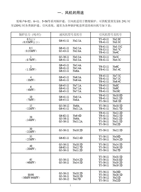
锅炉通风机设计成A式或D式传动,引风机设计成C式或D式传动。
右0°
右90°
右180°
风机的旋向及出口位置
右270°
A式传动
C式传动
D式传动
图1 风机的传动方式
60000y315s6b75千瓦联轴器传动7580170402436700169641784737258964356958171462926306103395016444592675559219491654155276750449944161387829134319795317334962891339089732042723g55611no112d1480203169714981001191629480y280m4b90千瓦联轴器传动7575140403469666869971836426384560869985166650242895566696614166324351539239621376517458350530950124643347954654394111461995029417219381125828g55611no142d99020227997472985191617180y315m6b90千瓦联轴器传动7580170652495909129821836301276682981970166637530857588895114165033129735129471376390329668886935124630834496345192611460783617568779231125714g55611no145d990202377103781992191685180y315l16b110千瓦联轴器传动751408017065260296796989183699628848835397716670783217808009571417220326378270953137709434377334594212470033596675589321146748377160559929112634415通风机产品性能及附件表型号转速rpm介质温度pa流量噪声dba有效功率kw设计工况参数配用电动机传动方式联轴器配用锅sa型号额定转速功率主轴电动机轴g55612no17d740201825137514981191697180110千瓦联轴器传动851408017090199812826097818371182215117072966166720324711070648671417349250610371294213772202640971869311247127276289518921114686828968024491
英飞风机尺寸及重量5.4版

1
离心风机箱
ISQ-575HPD4-3-GT
1
离心风机箱
ISQ-575HPD4-3-GT
1
离心风机箱
ISQ-575HPD4-3-GT
1
离心风机箱
ISQ-900-7.5-GT
1
离心风机箱
ISQ-575HPD4-3-GT
1
离心风机箱 离心风机箱
ISQ-500D4-2.2-GT
1
ISQ-425HPD4-0.75-GT 1
1
YFIAM高效轴流风机 GT
1
YFIAM高效轴流风机 YFIAM-630D4/0-1.1-GT 1
YFIAM高效轴流风机 YFIAM-710D4/15-4-GT
1
消防管道轴流风机 YFIAM-76030D4-/175.5-2.2-
1
YFIAM高效轴流风机 SYFRIAM-630D4/15-2.2-
2
YFIAM高效轴流风机 GYFTIAM-630D4/15-2.2-
1
YFIAM高效轴流风机 GYFTIAM-560D4/25-2.2-
2
YFIAM高效轴流风机 GT
3
YFIAM高效轴流风机 YFIAM-75160D4/10-31-.1G-T
1
YFIAM高效轴流风机 GYFTIAM-500D4/0-0.37-
136
地下北
P-B1-17-2
137
地下北
P-B1-20-1
138
地下北
P-B1-21-1
139
地下北
P-B1-22-1
140
地下北
P-B1-23-1
141
地下北
P-B1-24-1
4-68型离心风机型号讲解
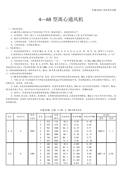
4—68型离心通风机一、风机的用途:4—68型离心通风机(以下简称风机)可作为一般通风换气。
其使用条件如下:1、应用场所:作为一般工厂及大建筑物的室内通风换气,既可用作输入气体,也可用作输出气体。
2、输送气体的种类:空气和其他不自燃的、对人体无害的、对钢铁材料无腐蚀性的气体。
3、气体内的杂质:气体内不许有粘性物质,所含的尘土及硬质颗粒物不大于150毫克/立方米。
4、气体的温度:不得超过80度。
二、风机的型式:1、本风机制成单吸入,机号有:№2。
8、3.15、3。
55、4、4。
5、5、6。
3、8、10、12。
5、16、20等十二个机号。
2、每种风机又可制成右旋转或左旋转两种型式,从电动机一端正视,叶轮按顺时针方向旋转,称为右旋转风机,以“右”表示。
按逆时针方向旋转,称为左旋转风机,以“左”表示.3、风机的出口位置,以机壳的出风口角度表示.“左”、“右"均可制成0o,45o,如135o,180o,225o共六种角度.4、风机的传动方式:有A、B、C、D四种,№2。
8-5采用A式,以电动机直联传动,风机的叶轮、机壳直接固定在电动机轴和法兰盘上(电动机用D2/T2型);N06。
3-12。
5采用悬臂支承装置,又分为C式(皮带传动皮带轮在轴承外侧)和D 式(用联轴器联接传动)两种传动方式;№l6、20为B式悬臂支承装置,皮带传动,皮带轮在轴承中间。
三、主要组成部分的结构特征4-68型风机的№2。
8-5主要由叶轮、机壳、进风口等部分配直联电动机组成。
№6。
3-20除上述部分外还有传动部分。
1、叶轮:由12片后倾翼形叶片焊接于孤锥型的轮盖与平板型的轮盘中间。
均用钢板制造,并经过静动平衡较正,空气性能良好,效率高,运转平稳。
2、机壳:机壳是普通钢板焊接而成的蜗形体,机壳作成两种不同型式,№2。
8—12.5机壳作成整体,不能拆开。
№16、20机壳作成三开式,除沿中分水平面分为两半外,上半部再沿垂直中心线分为两半,用螺栓连接。
风机使用说明书

风机使用说明书 This manuscript was revised on November 28, 2020风机使用说明书1、2、3、4、5、6、1、1.1外壳或电机外壳必须可靠接地1.2禁止反方向旋转,禁止超额定电流运行,禁止缺相运行;1.3风机轴承加油次数不少于1000小时/次1.4禁止在运转中维护风机2、2.1收货后立即检查风机包装是否完整无损,风机的铭牌参数是否符合要求,各随带附件是否齐全。
2.2仔细检查风机在运输过程中有无变形或损坏,坚固件是否松动或胶落,叶轮是否有擦碰现象,并对风机各部分零件进行检查。
如发现异常现象,应待修复后使用。
2.3用500W兆欧表测量风机外壳与电机绕组是的绝缘电阻,其值大于0.5兆欧,否则应对电机绕组进行烘干处理,烘干时温度不允许超过120℃,用手旋转风机叶轮,短时通电测试风机空转情况。
2.4准备好风机安装所需的各种材料、工具及场地。
3、3.1仔细阅读风机使用说明书及产品样本,熟悉和了解风机的规格、形式、叶轮旋转方向和气流进出方向等;再次检查风机各零部件是否完好,否则应待修复后方可安装使用。
3.2风机安装时必须有安全装置以防止事故发生,并由熟悉相关安全要求的专业人士安装和接线。
3.3联接风机进出口的风管有单独支撑,不允许将管道重叠重量加在风机的部件上;风机安装时应注意风机的水平位置,对风机与地基的结合面与出风管道的联接应调整,使之自然吻合,不得强行联接。
3.4风机安装后,用手或杠杆拨动叶轮,检查是否有过紧或擦碰现象,有无妨碍转动的物品,无异常现象下,方可进行试运转,风机传动装置的外露部份应有防护罩(用户自备)如风机进风口不接管道时,也需添置防护网或其他安装装置(用户自备)。
3.5风机所配电控箱必须与对应风机相匹配(指功率、电压、气动方式、控制形式等)。
3.6风机接线应由专业电工接线,接线必须正确可靠,尤其是电控箱处的接线编号与风机接线柱上的编号一致对应,风机外壳应可靠接地,接地必须可靠,不能用接零代替接地。
GY4-73F系列离心风机

沈阳风机厂有限公司 产品样本:锅炉通引风机 GY4-73F 式 网址:
用途及结构
G、Y4—73№20 F~31.5 F 是与 10 万。20 万千瓦火力发电机组配套的鼓引风机。 它是在 G、Y4—73Nn20 D~29.5 D 的基础上,根据 20 多年的生产和使用中存在的问题重新设 m 竹 新型产品。与原系列风机相比作了如下重大改进: 1.将原风机悬臂支承(D 式)传动方式改为中间支承(F 式)的传动方式,提高了风机运行的稳定性,其对 于引风机来说,由于叶轮磨损和积灰以后影响转子的平衡,容易引起风机振动,这一改进尤为重要。 2.通过模型(叶轮外径 D=1000 咖)试验,增加了适应于该型风机的进气室,改原进风口的形状为偏心 进风口。过去风机生产厂不制造附带进气室,而各电厂自行配置的气室多不能适应该风机的工作,容易引 起进气涡流,使风机的机壳、进气室以及风道产生剧烈振动,风机工况严重恶化,风量、压力、功率大幅 度波动,使设备不能正常运行,使用该系列新型风机,可使这一问题得以圆满解决。 3.在进气室的进口处装有翼形叶片调节门,用以调节风机的特性,提高风机的调节效率,调节叶片的 支撑处装有滚动轴承,转动灵活,使用可靠。 4.由于大部分送风机使用环境温度较高,轴承容易发热,因而新系列风机的轴承箱也和引风机一样采 用水冷式。 5.新风机轴承箱改进了油封设计,并增加了放气塞,解决了漏油问题。 6.由于滚动轴承标准的改变,新风机调整了轴承型号,同时由于传动方式的改变、轴的受力情况更为 合理,因而轴承在使用中出现的问题大为减少。 7.新风机的设计增强了机壳和进气室的刚性,在机壳和进气室的外部焊有适当高度的井字格筋板,内 部焊有空心管支撑,因而消除了由于机壳的刚性不足而产生的振动。 8.考虑到引风机叶轮的尘粒磨损问题,增大了翼形叶片头部的实心部分,并在叶片靠后盘处增加了防 磨板,同时在易磨损处用耐磨损焊条堆焊耐磨层,硬度可达 HRC48 以上,延长了叶轮的使用寿命,满足了 电厂使用和维修的要求。 9.按实际情况,新风机设计成进口 135。和出口 45。的型式,这样在不动风机主体和进出风口管道的 情况下,即可方便地拆除、进气室、进风口上的一部分,从而风机的转子可从上部垂直吊出。 10.扩大设计生产了№31.5F 鼓、引风机。 Y4—2×73№28.5F 锅炉离心引风机适用于火力发电厂中 30 万千瓦发电机组蒸汽锅炉引风系统,亦可 作为温度不超过 200℃气体排送。如用户选用此型风机时,所需性能为更适应于锅炉的配套需要,我厂可按 用户要求做相应的“点菜”设计。 Y4—2×73№28.5F 锅炉离心引风机采用双侧进气、双支撑结构,整个风机由转子组、机壳、进风口、 进气箱、调节门、传动组、滑动轴承、盘车装置及强制润滑系统等组成。叶轮叶片采取了耐磨措施,配套 双速电机及传动组,不但解决了气流转弯的稳定性,也提高了风机的调节效率。转子组经过动静平衡校正, 配制了强制供油润滑系统,因而风机能够长期稳定运行。
4-72离心风机型号

0.09
4 225 848 87.9 0.060
0. 186 1037 80.1 0.067
0.10
7 166 1131 73.5 0.071
0.11
1 1245 1825 79.9
0.79
1.11
2 1245 2093 84.3
0.86
1.20
2.78
3.34
2 2059 4534
86.2
3.01
3.61
4
A
2900
Y112M-2 4
3 2010 5083
88.9
3.19
3.83
4 1931 5633
90.0
3.36
4.03
4
A
4.5 A
4.5 A
5
A
5
A
1450 2900 1450 2900 1450
5 1794 6182 88.6 6 1627 6732 83.6 7 1431 7281 78.2 1 519 1992 82.3 2 509 2267 86.2 3 500 2542 88.9 4 480 2816 90.0 5 451 3091 88.6 6 402 3366 83.6 7 353 3641 78.2 1 2657 5790 83.3 2 2628 6573 87.0 3 2569 7355 89.5 4 2461 8137 90.5 5 2294 8920 89.2 6 2069 9702 84.5 7 1833 10485 79.4 1 666 2895 83.3 2 657 3286 87.0 3 637 3678 89.5 4 617 4069 90.5 5 568 4460 89.2 6 519 4851 84.5 7 460 5242 79.4 1 3314 8050 84.2 2 3265 9123 87.6 3 3187 10197 90.0 4 3049 11270 91.0 5 2844 12343 89.8 6 2589 13416 85.3 7 2304 14490 80.5 1 823 4025 84.2 2 813 4562 87.6 3 794 5098 90.0 4 764 5635 91.0 5 715 6172 89.8 6 647 6708 85.3 7 578 7245 80.5
企业信用报告_英飞同仁(江苏)风机有限公司
目录一、企业背景 (5)1.1 工商信息 (5)1.2 分支机构 (5)1.3 变更记录 (5)1.4 主要人员 (6)1.5 联系方式 (6)二、股东信息 (6)三、对外投资信息 (7)四、企业年报 (7)五、重点关注 (8)5.1 被执行人 (8)5.2 失信信息 (8)5.3 裁判文书 (9)5.4 法院公告 (9)5.5 行政处罚 (9)5.6 严重违法 (9)5.7 股权出质 (9)5.8 动产抵押 (9)5.9 开庭公告 (9)5.11 股权冻结 (10)5.12 清算信息 (10)5.13 公示催告 (10)六、知识产权 (10)6.1 商标信息 (10)6.2 专利信息 (10)6.3 软件著作权 (13)6.4 作品著作权 (13)6.5 网站备案 (13)七、企业发展 (13)7.1 融资信息 (13)7.2 核心成员 (13)7.3 竞品信息 (14)7.4 企业品牌项目 (14)八、经营状况 (14)8.1 招投标 (14)8.2 税务评级 (14)8.3 资质证书 (14)8.4 抽查检查 (14)8.5 进出口信用 (15)8.6 行政许可 (15)一、企业背景1.1 工商信息企业名称:英飞同仁(江苏)风机有限公司工商注册号:320691000189378统一信用代码:91320691MA1WTDKRX1法定代表人:张劲戈组织机构代码:MA1WTDKR-X企业类型:有限责任公司(自然人投资或控股的法人独资)所属行业:专用设备制造业经营状态:开业注册资本:20,000万(元)注册时间:2018-07-02注册地址:南通市海门经济技术开发区广州路1833号营业期限:2018-07-02 至无固定期限经营范围:风机及机组、电气设备成套装置、低压成套装置、电机、空气净化装置的生产,供热通风与空调工程设备(不含压力容器)、给排水设备、电动机、环保设备的销售和维修(除特种设备),机械设备安装(除特种设备),从事机械设备、环保设备技术领域内的技术服务、技术转让、技术开发、技术咨询;自营和代理上述商品和技术的进出口业务(国家限定公司经营或禁止进出口的商品除外)。
民用建筑通风系统产品介绍V1.2(20171020)
高效的通风方式
气流流速衰减示意
喷射通风效果侧视图
气体完全流通,不产生死角
降低废气浓度,避免污染物积累, 提高空气品质
英飞为某停车库诱导风机布局 做的CFD分析(过程展示)
智能化控制,节省运行成本
自动/手 动
手 动
高速/低速/ 停
自 动
<30ppm
≥100pp m 智能风机自动启动, 其连锁普通风机启 动
项目地址:杭州市滨湖路28号
使用产品:ISQ 项目挑战:受通风系统空间限制,要求安装 灵活,结构紧凑,噪音低。
暖 通 空 调 系 统 末 端 产 品
类别:公用-政府机关 项目名称:济南政务中心 项目地址:山东省济南市经东十路 使用产品:ISQ/YFICS/IAS/IMX 项目挑战:为匹配其建筑风格特点,要求 产品大风量、高静压,低噪音,外型美观 大气。
电机外置(消防型)
电机内置型
YFICK 低噪声离心风机箱
前弯、后倾两种叶轮形式内部风机
前弯双进风离心风机
特点:转速一般控制的比较低,噪音相对较小,叶
轮轻,制作工艺简单,成本较低。
后倾双进风离心风机
特点:转速覆盖范围广,提供大风量
和高静压, 后倾不易过载。
加强丝杠 前弯和后倾不同工作特性,扬长避短,选择各自擅长的应用区间。
•产品特点
中压区间,管道风机最佳选择 直联型结构,整体结构简单,维护简单方便 多种叶轮角度,满足不同工况高效选型需求
YFIMF 高效全混流风机
•产品特点
三维曲面叶片设计:更贴合气体运动 规律 闭式全混流叶轮:效率高,相比无前 盘开式叶轮效率大幅提升(平均 28%),且高效区宽 入口流线型文丘里管设计:相比其他 混流风机锥台式进气口,效率提升
PI2417562UB2M系列风机资料
PSC MOTOR & FAN , INC .深圳桐林散热设备有限公司Specification For ApprovalDC Brushless ImpellerModel: PI2417562UB2M SN:72-1-00Version: A05CustomerCustomer recognitionAcceptance ApprovalChina Office Address: Room 618, XingHe Building, Shajing Street, CentreRoad, Bao An District, Shenzhen, China, 518104Headquarter: 1851 Holser Walk, #204, Oxnard ,CA 93036, USAChina: Tel: +086-755-29541400 Fax: +086-755-29541195USA: Tel: (805) 9838300 Fax: (805) 9838400Website : E-mail :***************Approval Checked Editor WangweiAlex ZhuMark YiRevision HistoryName Version Content DateA01 Changed the name of the product 2011-05-08 Mark yiA02 Updated performance curve 2011-07-12 Mark yiA03 New logo change2011-09-01 Mark YiThe new company address has changeA04 New logo change2012-01-06 Mark YiBiA05Changed the corporate headquarters address2013-9-26 BillDATA SHEETModel : PI2417562UB2M Date:2013-09-26Customer: SN:72-1-00 Customer P/N: Version: A05Safety: UL E306337SPECIFICATION1.Dimension2.Bearing System Φ175×68.0 mm 2 Ball Bearing3.Rated V oltage 24VDC4.Operating V oltage 16~28VDC5.Starting V oltage 16 VDC6.Input Current 3.0A7.Input Power 72W8.Rated Speed 3800±5% RPM9.Rotation clockwise, seen on rotor10.Air Flow 399CFM (677.8m³/h)11.Static Air Pressure 1.93inH2O (49.04 mm H2O)12.Soft Start Yes13.Speed Control PWM or 0~10VDC14.Tachometer Output Open collector, 2 Pulses/Rev15.Auto Restart Yes16.Alarm Output No17.Noise Level 70.5dB(A)18.Lead Wire UL2464, AWG20#, L=500mm19.Connector No20.Ambient temperature -20~60℃21.Life Expectance 40,000 hours continuous operating at 25℃22.Insulation class "A"23.Operation mode Continuous operation (S1)24.Type of protection IP4225.Number of blades 726.Dielectric Strength 500V AC/60Hz, 1 min, Leakage current <=5.0mA Weight 790 g28.Packing Corrugated carton, 12Pcs/cartonPERFORMANCE CURVESAirflow-CFMAirflow-m³/hMODEL NUMBERING SYSTEMP:P I 48PSCMF Model:F:Axial FanB:Blower C:Fan in heat sinkI:Impeller M:Motor Voltage:12=12VDC24=24VDC 48=48VDC1A=100~120VAC 2A=220~240VAC1E=100~120VAC-EC2E=220~240VAC-EC Dimension:17562=φ175X62mm12038=120X120X38mmSpeed:T: Super High SpeedU: Ultra High Speed H: High SpeedM: Medium Speed L: Low speedX: Extra Low Speed 17562Bearing:S1=Sleeve Bearing B1=One Ball Bearing and one Sleeve B2=Two Ball BearingFunction:N:Two wire R:Alarm D:Two Speed controlM:Speed control -F:FG S:Stable SpeedH B2MNotes1.PSCMF will not guarantee the products if the application of our products hasexceeded the limitation which is specified on this specification.2.Please do not touch the impeller with pressure and never handle the fan by theleadwires. The bearings and lead wire may be damaged.3.PSCMF does not guarantee the product against the safety problems or failurescaused by powder dust, drops of water or any object impeding the blade4.If there is any data or related documentation different from this data sheet, this datasheet is the principal reference.5.For the purpose of MIS, please indicate SPEC No. on every order.6.In case the fan has no polarity protection function, wires with the samecolor(electrode) must be connected together during the assembly. (i.e: red+red,black+black) or the fan will be damaged immediately.7.Please do not use the fan in the environment of corrosive gas, liquid or anydetrimental gas.8.Please do not store the fan in an environment of high/low temperature , highhumidity or any detrimental gas. Please store the fan within 6 months , every6 months there should be linkage of electrical current to the fan, even though the fanis stored in room temperature.9.While the fan is in operation, please do not lock the fan intentionally for a longperiod of time, because the continuous stoppage will over-heat the IC and thusburn-out of the fan.10.During the installation of the fan, please pay substantial attention to possible noisecaused by resonance vibration.。
Twin City AXICO ANTI-STALL可调旋翼风机系列产品说明书
CATALOG AX351 | JUL Y 2001WWW.TCF.COMTwin City FanAXICO ANTI-STALL ®CONTROLLABLE PITCH-IN-MOTION ANDADJUSTABLE PITCH-AT-REST VANEAXIAL FANS FPAC | FPMC | FPDATwin City Catalog AX3512AXICO ANTI-STALL ® is the only controllable pitch vaneaxial fan designed to totally eliminate stall, sys-tem surging and increased noise levels often expe-rienced by ordinary controllable pitch vaneaxial fans under unstable conditions.Normal axial fans can be forced to perform within unstable working ranges when operating conditions are unfavorable. This can happen when the fan sys-tem is subjected to sudden or unexpected variations in pressure which can be caused by:• dampers that close suddenly or fail to open • hypersensitive automation control systems • improper parallel fan starting sequences• incorrect or optimistic pressure drop calculations • clogged filters, etc.When a fan operates in an unstable range the blades are submitted to sharp variations in pressure which will ultimately result in blade fatigue and even-tual fan failure.AXICO ANTI-STALL ® provides a patented solution to solve the problems associated with fan stall in a simple, ingenious method, without the addition of any moving parts or expensive electronic controls. The secret lies in the small bypass vanes that are inte-grated into the chamber placed around the periphery of the fan impeller. The bypass vanes “catch” tur-bulent airflows produced at the tips of the blades, which normally cause stalling, and restore them to stability in the proper flow direction.AXICO ANTI-STALL ® has no stall area and no stall limit. While this means that the AXICO ANTI-STALL ® can be selected directly at any point on the perfor-mance curves in this bulletin without consideration of any safety range against the possibility of stall, we strongly recommend selections be made toward the central part of the fan curve at the point of highest possible efficiency.Anti-stall ring with bypassvanesNEMA designed foot-mounted motor com-pletely exposed for ease of service andaccessibility.Motor supported onstructural baseupstream of propeller.Inlet bell designed exclusively for free inlet applications such as custom air handlers (duct configurations also available.)Vane section provided with removable access panel to provide unimpeded access to fan impeller and blade actuator mechanism.Fan supported from awelded steel channel base (minimum 5" channel).Note: Standard inlet guards have been removed for clarity.Capabilities:• Impeller diameters from 311∕2" to 783∕4"• Capacities of 2,000 to 200,000 CFM • Static pressures to 10" w.g.AXICO ANTI-STALL ®Twin City Catalog AX3513FPACVariable air volume fan impeller is equipped with an internal pneumatic diaphragm and external Honeywell industrial-grade pilot positioner assembly to simulta-neously vary the pitch angle of all blades identically while the fan impeller is rotating at motor speed. An 80 to 100 psi pneumatic supply air line is required for pitch actuation of this fan. These fans typically operate in a direct-acting mode in conjunction with the building automation temperature control system. The standard pneumatic pilot positioner receives a 3 to 15 psi control signal from the building automation system to modulate the fan blades. An optional elec-tro-pneumatic positioner is available that will modulate blade pitch after receipt of an externally generated 4-20mA electronic control signal.FPMCVariable air volume fan impeller is equipped with a mechanical linkage system that will simultaneously actuate the pitch angle of all blades via one of three basic options:1. A manual lever arm with locking quadrant mounted external to the fan housing.2. A right-angle gear box with manual handwheel mounted external to the fan housing3. A lever arm with electric motor actuator mounted external to the fan housing and capable of auto-matic remote pitch actuation responding to either a 4-20mA or a 135 ohm electronic control signal received from the building-automated temperature control system.FPDAConstant air volume fan impeller is equipped with mechanically-fixed, individually manually-adjustable blades that may only be re-pitched when the fan is stopped. This fan may be operated with a variable frequency drive unit to vary the rotational speed of the impeller and thereby vary the air volume pro-duced while maintaining the ANTI-STALL ® character-istics of the unit.The AXICO ANTI-STALL ® fan can easily be controlled to deliver the required flow or pressure in most situations by properly sizing the fan and then adjusting the blade angle of attack while fan is energized. Blade pitch control can be accomplished in the following ways.Pneumatic Controllable PitchElectric Controllable PitchManual Adjustable PitchVAV Control Flexibility4View of AXICO ANTI-STALL®fan from discharge.Honeywell industrial-gauge pilot positioner withclosed-loop feedback cable is shown standardlymounted on top of straightening vane section. Bolt-on vane section allows 360° rotation to allow simplefield adjustment for improved job site accessibility ofpilot positioner.Similar view of fan discharge with standard accesspanel removed. Every AXICO ANTI-STALL®fanincludes a 17.75" long by 90° of fan circumferenceaccess panel located in straightening vane section.Total service accessibility is provided by this exclu-sive feature.As can be seen in this close-up of the inlet bell con-tinuously welded to the patented ANTI-STALL® ring,an exclusive AXICO® feature, ANTI-STALL® is accom-plished by welded bypass vanes without the use ofany extra moving parts or electronic “black boxes.”A close-up of the pneumatic controllable pitch impel-ler mechanism viewed through the standard accesspanel. Pneumatic supply air (80 to 100 psi) is intro-duced to the diaphragm through the rotary union(center of photo with feedback cable attached) inflat-ing the pneumatic piston forcing the spider arms tomove away from the hub and increase the bladeangle of attack. Construction FeaturesTwin City Catalog AX351CFM (A)FANSIZE(B)RPM(C)HUBSIZE(D)(E)TP SP300,000 200,000100,0009080706050403020251512*200*180 *160140 125112351009080 10,0009876543210,000900***8-101200****6-8*****5-810.012.011.09.010.08.07.07.09.08.06.06.0 5.05.04.04.03.03.02.02.01.01.00.90.90.80.80.70.70.60.60.50.54.04.00.30.30.20.21800*900 & 1200 RPM only ***Size 112 to 200 only ****Size 90 to 180 only *****Up to size 140 onlyStep 1. Draw a line from the appropriate CFM on vertical axis marched CFM (A) to the appropriate RPM on vertical axis marked RPM (C). The point at which this line intersects the vertical axis marked FAN SIZE (B) indicates the most appropriate fan size given that RPM and CFM. As an example, a line drawn between 60,000 CFM and 1800 RPM intersects the fan size line almost precisely in the middle of the area noted as 112. Based upon this, it is probable that a size 112 fan is the best selection. The same line intersects the fan size line at the border between size 125 and size 100. This indicates that a 125 is probably over-sized and a 100 is probably undersized. There may be circumstances where these selections should be investigated. If that is the case, you should consult your local sales representative.Step 2. Having now selected the fan, one must now select the hub and blade combination which is appro-priate. Draw a line from the vertical axis RPM (C) to the vertical axis marked TP/SP (E). In the example shown we have a given value of 4.25" of static pres-sure. Be sure that you use the same fan speed in selecting the hub and blade as you have used in selecting the fan. In this case, we draw the line from 1800 RPM to 4.25" static pressure and it intersects the HUB SIZE vertical axis (D) close to the middle of the zone marked 5-8. This would indicate that the probable selection for 60,000 CFM and 4.25" static pressure is 112-5-8. Note that the same line inter-sected the hub size vertical axis almost at the 6-8 junction. This indicates that the pressure is probably low so that utilization of a 6 hub with 8 blades will result in relatively low efficiencies. NOTE: See perfor-mance curve on page 6.Fan Selection ProcessTwin City Catalog AX3515AXICO ANTI-STALL® fans are characterized by completely stable high efficiency operation over an extremely wide operating range. The risk of stall (surging, instability, etc.) encountered in conventional vaneaxial fan designs has been completely eliminated. Fan performance in this publication is presented as Total Pressure versus CFM at standard air density (0.075 lbs/ft3). The maximum blade angles presented in the published performance curves are the maxi-mum angles for which the fan is designed.For controllable pitch in-flight fans in variable volume situations the maximum design load should ideally be selected to the right and slightly above the peak efficiency ring so that normal operation at modulated partial loads will result in operation at areas of high-est efficiency on the fan curve.Fans with manually adjustable pitch blades for appli-cations in either constant volume or variable speed (frequency) systems should ideally be chosen for normal operation within the peak efficiency ring of the fan curve to insure the highest possible energy savings throughout the complete range of operation. The pressure/flow characteristic of the fan is pre-sented as a total pressure rise between the fan inlet and the fan outlet, providing that the fan is connected to ductwork of the same diameter as the fan. The curves are applicable to either a free or a duct connection at the fan inlet and no provision is made for less than ideal fan inlet conditions within the performance curves. The outlet side of the fan is often connected to a conical regain diffuser that is in turn connected to ductwork or a discharge ple-num. Various system requirements and layouts result in numerous combinations of standard or compact fan designs often used in conjunction with a variety of discharge options (ductwork, outlet transitions, C-D diffusers, acoustic diffusers, etc.). The pressure regain and or applicable discharge connection losses for any instance other than that of a fan connected directly to fan diameter discharge ductwork requires the inclusion of these losses in all presentations of Total Pressure.The following explanation of the performance curves, associated fan laws and formulas should be used to determine and analyze various aspects of fan per-formance.SP = Static PressureVP = Velocity PressurePv = Velocity pressure in fan diameter ductPvD = Velocity pressure in diffuser diameter duct DL = Discharge LossTP = Total PressureTE = Total EfficiencybHP = Brake HorsepowerTP = SP + VP + DLCFM x TPbHP =6356 x TEFan chart is valid for a gas density of .075 lb/ft3.L wt: Total sound power level dB(A)P v: Velocity pressure in fan diameter ductP vD: Velocity pressure in diffuser diameter ductTE: Total efficiencyAspects of Fan SelectionTwin City Catalog AX351 6Twin City Catalog AX3517F ___ - __ - ___ - __ - ___ - ____ - ___AXICO ® = PAC = PDAARR. 4 TYPE 22 = HORIZONTAL FLOOR LEG 4 = HORIZONTAL CEILING CLIP 6 = VERTICAL CLIP ARR. 4 TYPE 33 = FLOOR MOUNT FAN SIZE (cm)080, 090, 100, 112, 125 140, 160, 180, 200MOTOR HP MOTOR RPMBLADE COUNT 8 = IF 5 OR 6 HUB 10 = IF 8 HUB HUB SIZE5 = 50.0 cm Dia.6 = 63.0 cm Dia. 8 = 80.0 cm Dia.NOTES:1. Motor frame size must be specified in the body of the order and will no longer be indicated within the model number.2. Blade pitch setting must be indicated in the body of the order.DIMENSIONS ARE NOT TO BE USED FOR CONSTRUCTION. *SHIP WEIGHT LESS MOTORModel Number DesignationFPDA Compact Design (Arr. 4 Type 3)TWIN CITY FAN & BLOWERWWW.TCF .COM5959 TRENTON LANE N | MINNEAPOLIS, MN 55442 | PHONE: 763-551-7600 | FAX: 763-551-7601CENTRIFUGAL FANS | UTILITY SETS | PLENUM & PLUG FANS | INLINE CENTRIFUGAL FANSMIXED FLOW FANS | TUBEAXIAL & VANEAXIAL FANS | PROPELLER WALL FANS | PROPELLER ROOF VENTILA TORS CENTRIFUGAL ROOF & WALL EXHAUSTERS | CEILING VENTILA TORS | GRAVITY VENTILA TORS | DUCT BLOWERSRADIAL BLADED FANS | RADIAL TIP FANS | HIGH EFFICIENCY INDUSTRIAL FANS | PRESSURE BLOWERS LABORA TORY EXHAUST FANS | FILTERED SUPPL Y FANS | MANCOOLERS | FIBERGLASS FANS | CUSTOM FANSINDUSTRIAL PROCESS ANDCOMMERCIAL VENTILATION SYSTEMS©2018 Twin City Fan Companies, Ltd., Minneapolis, MN. All rights reserved. Catalog illustrations cover the general appearance of Twin City Fan & Blower products at the time of publication and we reserve the right to make changes in design and construction at any time without notice.Twin City FanTwin City Fan。