Force10交换机配置手册
迈普交换机配置
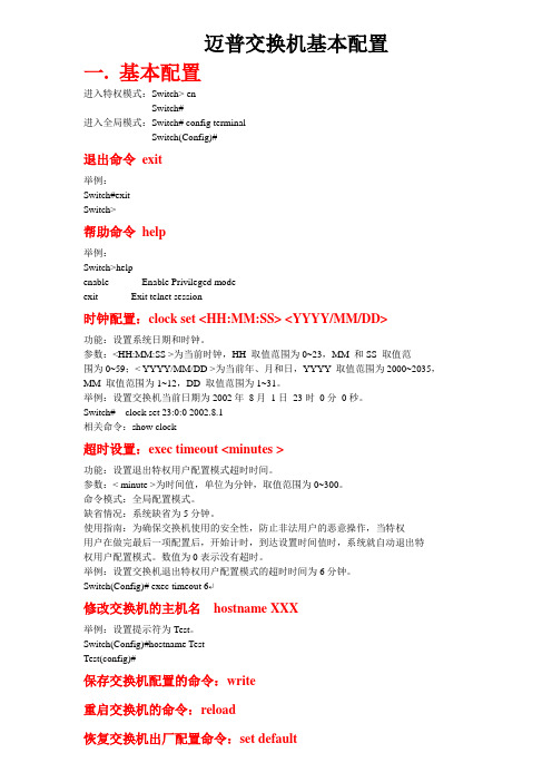
迈普交换机基本配置一. 基本配置进入特权模式:Switch> enSwitch#进入全局模式:Switch# config terminalSwitch(Config)#退出命令exit举例:Switch#exitSwitch>帮助命令help举例:Switch>helpenable -- Enable Privileged modeexit -- Exit telnet session时钟配置:clock set <HH:MM:SS> <YYYY/MM/DD>功能:设置系统日期和时钟。
参数:<HH:MM:SS >为当前时钟,HH 取值范围为0~23,MM 和SS 取值范围为0~59;< YYYY/MM/DD >为当前年、月和日,YYYY 取值范围为2000~2035,MM 取值范围为1~12,DD 取值范围为1~31。
举例:设置交换机当前日期为2002年8月1日23时0分0秒。
Switch# clock set 23:0:0 2002.8.1相关命令:show clock超时设置:exec timeout <minutes >功能:设置退出特权用户配置模式超时时间。
参数:< minute >为时间值,单位为分钟,取值范围为0~300。
命令模式:全局配置模式。
缺省情况:系统缺省为5分钟。
使用指南:为确保交换机使用的安全性,防止非法用户的恶意操作,当特权用户在做完最后一项配置后,开始计时,到达设置时间值时,系统就自动退出特权用户配置模式。
数值为0表示没有超时。
举例:设置交换机退出特权用户配置模式的超时时间为6分钟。
Switch(Config)# exec timeout 6↵修改交换机的主机名hostname XXX举例:设置提示符为Test。
Switch(Config)#hostname TestTest(config)#保存交换机配置的命令:write重启交换机的命令:reload恢复交换机出厂配置命令:set default举例:Switch#set defaultAre you sure? [Y/N] = ySwitch#writeSwitch#reload更改语言命令:language {chinese|english}功能:设置显示的帮助信息的语言类型。
交换机的基本配置

交换机的基本配置交换机的基本配置一、交换机的几种配置方法本部分包括以下内容:控制台远程登录其它配置方法本部分内容适用于交换机、路由器等网络设备。
控制台登录后,就可以对网络设备进行配置了。
说明:超级终端只需安装一次,下次再使用时可从“开始 | 程序 | 附件 | 通信 | 超级终端”中找到上次安装的超级终端,直接使用即可。
远程登录通过一台连接在网络中的计算机,用Telnet命令登录网络设备进行配置。
远程登录条件:1、网络设备已经配置了IP地址、远程登录密码和特权密码。
2、网络设备已经连入网络工作。
3、计算机也连入网络,并且可以和网络设备通信。
说明:远程登录的计算机不是连接在网络设备Console口上的计算机,而是网络中任一台计算机。
远程登录方法:在计算机的命令行中,输入命令“telnet 网络设备IP地址”,输入登录密码就可以进入网络设备的命令配置模式。
说明:远程登录方式不能用来配置新设备,新设备应该用控制台配置IP地址等参数,以后才能使用远程登录进行配置。
其它配置方法除了控制台和远程登录之外,还有其它一些配置方法配置网络设备。
1、TFTP服务器:TFTP服务器是网络中的一台计算机,你可以把网络设备的配置文件等信息备份到TFTP服务器之中,也可以把备份的文件传回到网络设备中。
由于设备的配置文件是文本文件,所以,你可以用文本编辑软件打开进行修改,再把修改后的配置文件传回网络设备,这样就可以实现配置功能。
你也可以用TFTP服务器把一个已经做好的配置文件上传到一台同型号的设备中实现对它的配置。
2、SSH:SSH是一种安全的配置手段,其功能类似于远程登录。
与T elnet 不同的是,SSH传输中所有信息都是加密的,所以如果需要在一个不能保证安全的环境中配置网络设备,最好使用SSH。
3、Web:有些种类的设备支持Web配置方式,你可以在计算机上用浏览器访问网络设备并配置。
Web配置方式具有较好的直观性,用它可观察到设备的连接情况。
DELL+Force10交换机

DELL Force10交换机简明配置手册Mark Wang2015年4月12日目录1简介 (1)2写在前面 (1)3Console使用 (1)4交换机使用技巧 (2)4.1TAB键自动补全 (2)4.2善于使用问号 (2)4.3反向删除命令 (3)5BMP/Jump-Start模式 (3)6接口的基本配置 (4)6.1接口启用 (4)6.2接口速率修改 (5)7交换机管理 (5)7.1启用Telnet/SSH服务 (5)7.2创建用户名和密码 (5)7.3管理IP的配置 (6)7.3.1带内管理IP (6)7.3.2带外管理IP (6)7.4保存交换机配置 (6)7.5重启交换机 (6)7.6恢复默认设置 (7)8交换机时间与日期 (7)8.1本地系统时间 (7)8.2NTP校时服务器 (7)8.3日志时间戳 (7)9Access/Trunk/Hybird配置 (7)9.1例1.配置Access模式 (8)9.2例2.配置Trunk模式 (8)9.3例3.配置Hybird模式 (8)10生成树配置 (9)10.1RSTP协议 (9)10.2PVST协议 (10)10.3MSTP协议 (10)11链路聚合配置 (11)11.1例1.静态聚合 (11)11.2例CP动态聚合 (11)12VRRP配置 (12)12.1Master主机配置VRRP (12)12.2Standby主机配置VRRP (13)13802.1X认证 (13)14LLDP配置 (14)15DHCP服务器 (14)16本地端口镜像 (15)17sflow配置 (15)18上行链路状态跟踪 (15)19恢复密码 (16)20交换机固件更新 (16)21收集日志 (16)22附录一 (17)23附录二 (17)1简介目前DELL有定位为园区/企业级别的PowerConnect系列交换机、N系列交换机以及定位为数据中心级别的Force10系列交换机(下文可能会简称为F10),其中Force10系列交换机还分为S系列、C系列、E系列、Z系列以及刀箱上的MXL/MIO等。
Force10 Networks E-Series ExaScale 升级程序说明书

TeraScale to ExaScale Upgrade ProcedureThe E-Series TeraScale is easily upgraded to Force10 Networks E-Series ExaScale. These upgrade requirements outline the necessary components and procedures required to upgrade the E1200i with FTOS version 8.1.1.0. Direct any questions regarding the upgrade to Force10 Networks’ Customer Support.E-mail:***************************Web: /support/Telephone:US and Canada: 866.965.5800International: 408.965.5800Supported HardwareHardware Catalog Number Minimum Software Version RequiredE1200i Chassis (Note 1)CH-E1200I-ACCH-E1200I-DC8.1.1.1AC Power Supply 2800W CC-E1200I-2800W-AC8.1.1.1 DC Power Entry Module CH-E1200I-DC8.1.1.1 Route Processor Module—ExaScale LC-EH-RPM8.1.1.1 Switch Fabric Module (Note 2)CC-E-SFM38.1.1.1 10 port 10GE line card (10M CAM)LC-EH-10GE-10S8.1.1.1 10 port 10GE line card (40M CAM)LC-EJ-10GE-10S8.1.1.1 Fan Tray CC-E-1200I-Fan8.1.1.1Upgrading HardwareExaScale SFM RequirementsE-Series ExaScale systems and FTOS Release 8.1.1.1 require SFM version 752-00265-03 Rev 01 or higher. Earlier SFMs do not support line rate following the ExaScale 8.1.1.1 FPGA upgrade.Do not mix SFMs. All the SFMs in the chassis must run the required minimum software version.The automatic upgrade process takes place regardless of the SFMs you have installed. If you have one or more SFMs that are earlier than 752-00265-03 Rev 01, a SYSLOG message (Message1) appears during the upgrade . Message 1 SYSLOG messages during FPGA Automatic Upgrade00:00:52: %RPM1-P:CP %TSM-5-SFM_OLDER_VERSION: Older version of SFM 8 detected00:00:52: %RPM1-P:CP %TSM-5-SFM_FOUND: Found SFM 800:00:51: %RPM1-P:CP %TSM-5-SFM_OLDER_VERSION: Older version of SFM 7 detected00:00:51: %RPM1-P:CP %TSM-5-SFM_FOUND: Found SFM 700:00:51: %RPM1-P:CP %TSM-5-SFM_FOUND: Found SFM 600:00:50: %RPM1-P:CP %TSM-5-SFM_FOUND: Found SFM 500:00:49: %RPM1-P:CP %TSM-5-SFM_FOUND: Found SFM 400:00:48: %RPM1-P:CP %TSM-5-SFM_FOUND: Found SFM 300:00:48: %RPM1-P:CP %TSM-5-SFM_FOUND: Found SFM 200:00:47: %RPM1-P:CP %TSM-5-SFM_FOUND: Found SFM 100:00:47: %RPM1-P:CP %TSM-5-SFM_FOUND: Found SFM 0The show sfm command includes information for any SFM that needs to be upgraded (Figure3).FPGA UpgradesFTOS version 8.1.1.1 introduces an automatic FPGA Upgrade process. It allows easy upgrades to newer SFM version by implementing an auto-detection of mismatched SFM version. The upgrade to the mismatched SFMs is done automatically.Manual upgrade are still supported for one or all SFMs.Automatic upgrade during boot, reboot, reload, or restartThe FPGA auto upgrade takes place when any SFMs in the chassis run an FPGA version lower than the version running during the boot, reboot, reload and restart operations. During the auto upgrade process, the system displays messages relaying the status of the upgrade process (Figure1). To verify the result of the SFM version upgrade, use the show sfm command.Figure 1 FPGA Automatic Upgrade Messages**************************************************************************** Warning Warning Warning** -------------------------------------------------------------------------------------** Starting auto upgrade of SFMs to newer version 0x0.0.3* Please wait until upgradation of all 5 SFMS is complete.** SFM will restart itself after upgradation of all 5 SFM is complete !***************************************************************************SFM 0/5 upgrade startedSFM 0/5 is upgraded to revision 0x0.0.3.SFM 1/5 upgrade startedSFM 1/5 is upgraded to revision 0x0.0.3.SFM 2/5 upgrade startedSFM 2/5 is upgraded to revision 0x0.0.3.SFM 3/5 upgrade startedSFM 3/5 is upgraded to revision 0x0.0.3.SFM 4/5 upgrade startedSFM 4/5 is upgraded to revision 0x0.0.3.*************************************************************** Warning Warning Warning** -----------------------------------------------------------** Auto upgrade on all 5 SFM to version 0x0.0.3 is complete.** Rebooting chassis ....**************************************************************Verify the result of the SFM version upgrade using the show sfm command.Automatic upgrade for one or more new SFMsThe FPGA auto upgrade takes place when any newly inserted SFM runs an FPGA version lower than the version running on the SFMs in the chassis. During this auto upgrade process, the system displays messages relaying the status of the upgrade process (Figure2). To verify the result of the individual SFM version upgrade, use the show sfm slot command.Figure 2 New SFM Automatic Upgrade Messages**************************************************************************** Warning Warning Warning** -----------------------------------------------------------------------** Starting auto upgrade of SFMs to newer version 0x0.0.3* Please wait until upgradation of 1 SFM is complete.** SFM will reset itself after upgradation of 1 SFM is complete !***************************************************************************SFM 0/9 upgrade startedSFM 0/9 is upgraded to revision 0x0.0.3.*************************************************************** Warning Warning Warning** -----------------------------------------------------------** Auto upgrade on 1 SFM to version 0x0.0.3 is complete.** Resetting SFM .... Please wait ....**************************************************************SFM 0/9 reset started00:08:29: %RPM1-P:CP %TSM-6-SFM_USR_RESET: SFM 0 reset by userreset SFM 0 successful !*************************************************************** Warning Warning Warning** -----------------------------------------------------------** Resetting on 1 SFM to revision 0x0.0.3 is complete !**************************************************************TeraScale to ExaScale UpgradeBe sure you have the correct ExaScale hardware ready for installation prior to beginning this upgrade. Refer to Supported Hardware for the list of hardware required for E-Series ExaScale with FTOS 8.1.1.1.Step Command Syntax Command Mode Purpose1Turn the On/Standby switch toStandby (AC).Turn the Remote Power Source toOff (DC).Power-off the chassis.2Replace the TeraScale RPMs, SFMs and linecards with ExaScale RPMs, SFMs and linecards.Refer to the RPM, SFM and Linecard documentation for installation and replacement details.3Turn the On/Standby switch to ON(AC)Turn the Remote Power Switch to ON(DC).Power on the chassis4The chassis automatically powers up with a ExaScale image if the RPM has been programmed to boot from particular FTP location or Flash that points to a TeraScale image. If no image is configured, go to Steps 5 and 6.5Ctrl+Shift+6Stop the chassis in boot user mode andconfigure it to boot from FTP or Flashand reload.6boot change{primary|secondary|default}After entering the keywords anddesired option, press Enter. Thesoftware prompts you to enter thefollowing:• boot device (ftp, tftp, flash, slot0)• image file name• IP address of the server with theimage• username and password (only forFTP)BOOT_USER Tell the system where to access theExaScale FTOS image used to boot thesystem:•Enter primary to configure the bootparameters used in the first attemptto boot the system.•Enter secondary for when theprimary operating system bootselection is not available.Enter default to configure bootparameters used if the secondaryoperating system boot parameterselection is not available. The defaultlocation should always be the internalflash device (flash:), and a verifiedimage should be stored there.7reload BOOT_USER Restart the chassis to boot with thespecified ExaScale image.8show chassis EXEC Privilege We can confirm using the show chassiscommand.Step Command Syntax Command Mode Purpose Force10#show chassis-- Manufacturing Info --Chassis Type : E600iChassis Mode : ExaScaleChassis Epoch : 10.4 micro-secondsChassis MAC : 00:01:e8:41:cb:36Serial Number : TY000001140Part Number : 7520023900Vendor Id : 04Date Code : 01012008Country Code : 01Product Rev : 03ExaScale to TeraScale DowngradeStep Command SyntaxCommand Mode Purpose1chassis chassis-mode terascaleEXEC PrivilegeChange the chassis mode to TeraScale.2Turn the On/Standby switch to Standby (AC).Turn the Remote Power Source to Off (DC).Power-off the chassis.3Replace the ExaScale RPMs, SFMs and linecards with TeraScale RPMs, linecards and SFMs.Refer to the RPM, SFM and Linecard documentation for installation and replacement details.4Turn the On/Standby switch to ON (AC)Turn the Remote Power Switch to ON (DC).Power on the chassisThe chassis automatically powers up with a TeraScale image if the RPM has been programmed to boot from particular FTP location or Flash that points to a TeraScale image. If no image is configured, go to Steps 5 and 6.5Ctrl+Shift+6when prompted during boot mode Stop the chassis in boot user mode and configure it to boot from FTP or Flash and reload.6boot change{primary|secondary|default }After entering the keywords and desired option, press Enter . The software prompts you to enter the following:• boot device (ftp, tftp, flash, slot0)• image file name• IP address of the server with the image• username and password (for FTP)BOOT_USERTell the system where to access the TeraScale FTOS image used to boot the system:•Enter primary to configure the boot parameters used in the first attempt to boot the system.•Enter secondary for when the primary operating system boot selection is not available.Enter default to configure boot parameters used if the secondary operating system boot parameter selection is not available. The default location should always be the internal flash device (flash:), and a verified image should be stored there.7reload BOOT_USERRestart the chassis to boot with the specified TeraScale image.Force10#chassis chassis-mode terascaleChassis mode changed to TeraScale mode. Please reload chassis now.System configuration has been modified. Save? [yes/no]: y Proceed with reload [confirm yes/no]:yStep Command Syntax Command Mode Purpose8show chassis EXEC Privilege We can confirm using the show chassiscommand.Force10#show chassis-- Manufacturing Info --Chassis Type : E1200Chassis Mode : TeraScaleChassis Epoch : 10.4 micro-secondsChassis MAC : 00:01:e8:05:db:05Serial Number : 7520010900Part Number : 0Vendor Id : 04Date Code : 11252003Country Code : 01Product Rev : 02。
戴尔网络和Force10 S4820T交换机配置指南说明书

Dell Networking S4820T and Dell Force10 S4820TSwitch Configuration Guide for PS Series SANsDell Storage EngineeringFebru ary 2016RevisionsTHIS WHITE PAPER IS FOR INFORMATIONAL PURPOSES ONLY, AND MAY CONTAIN TYPOGRAPHICAL ERRORS AND TECHNICAL INACCURACIES. THE CONTENT IS PROVIDED AS IS, WITHOUT EXPRESS OR IMPLIED WARRANTIES OF ANY KIND.© 2013–2016 Dell Inc. All rights reserved. Dell, the DELL logo, and the DELL badge are trademarks of Dell Inc. Other trademarks and trade names may be used in this document to refer to either the entities claiming the marks and names or their products. Dell disclaims any proprietary interest in the marks and names of others.Table of contents1Introduction (5)1.1Audience (5)1.2Switch details (5)1.3Cabling diagram (7)2Dell recommended switch configuration (8)2.1Hardware configuration (8)2.2Delete startup configuration (8)2.3Configure out of band (OOB) management port (8)2.4Configure route for OOB management port (optional) (9)2.5Configure login credentials (9)2.6Enable switch ports (9)2.7Enable Jumbo Frames (10)2.8Configure flow control (10)2.9Configure spanning tree on edge ports (10)2.10Configure port channel for LAG (10)2.11Configure QSFP ports for LAG (10)2.12Save configuration (11)2.13Configure additional switch (11)3Configure Data Center Bridging (DCB) (optional) (12)3.1Disable 802.3x flowcontrol on SFP+ ports (12)3.2Disable 802.3x flowcontrol on all QSFP ports (12)3.3Enable DCB and reload (12)3.4Create tagged VLAN for all ports and port-channels (12)3.5Configure DCB policies (13)3.6Apply policies to switch ports (13)3.7Save configuration (13)3.8Configure additional switches (14)4Reverting from DCB to non-DCB configuration (optional) (15)4.1Disable DCB (15)4.2Remove DCB policies and apply standard flow control (15)4.3Revert to default VLAN ID on switch and arrays (15)4.4Save configuration (16)4.5Reload (16)4.6Verify DCB status (16)4.7Configure additional switch (16)5Optional stack configuration (17)5.1Delete startup configuration on the first switch (17)5.2Configure stack on the first switch (17)5.3Delete startup configuration on the second switch (18)5.4Configure stack on the second switch (18)5.5Verify stack configuration (18)5.6Configure out of band (OOB) management port (19)5.7Configure route for OOB management port (optional) (19)5.8Configure login credentials (19)5.9Configuring switch ports (19)5.10Save configuration (20)Additional resources (21)1IntroductionThis document illustrates how to configure Dell Networking or Dell™ Force10 S4820T switches for usewith Dell PS Series storage using Dell best practices. The recommended configuration uses linkaggregation groups (LAGs) for inter-switch connections. Optional steps are provided in section 3 to enable Data Center Bridging (DCB).1.1AudienceThis switch configuration guide describes an optimal configuration following Dell best practices for a PSSeries iSCSI SAN and is intended for storage or network administrators and deployment personnel.1.2Switch detailsThe table below provides an overview of the switch configuration.1.3Cabling diagramThe cabling diagram shown below represents the Dell recommend method for deploying your servers and PS arrays.Figure 1Cabling diagram2Dell recommended switch configurationThese steps show you how to configure two Dell Networking or Force10 S4820T switches with a LinkAggregation Group (LAG). The switches are interconnected using two of the 40 GbE Quad Small Form-factor Pluggable (QSFP) uplink ports, and the LAG is configured for Dynamic Link Aggregation ControlProtocol (LACP).2.1Hardware configuration1.Power on the two switches.2.Connect a serial cable to the serial port of the first switch.ing Putty or another terminal utility, open a serial connection session to the switch.4.Open your terminal emulator and configure it to use the serial port (usually COM1 but this may varydepending on your system). Configure serial communications for 9600,N,8,1 and no flow control.5.Connect the (QSFP) LAG cables between the switches, by connecting port 48 on switch 1 to port 48on switch2 and port 52 on switch 1 to port 52 on switch 2. See this configuration in Figure 1.2.2Delete startup configurationFTOS>enableFTOS#delete startup-configProceed to delete startup-config [confirm yes/no]yesFTOS#reloadSystem configuration has been modified. Save? [yes/no]noProceed with reload [confirm yes/no]yes2.3Configure out of band (OOB) management portFTOS>enablePassword:FTOS>#configFTOS(conf)#interface Managementethernet 0/0FTOS(conf-if-ma-0/0)#ip address ipaddress maskFTOS(conf-if-ma-0/0)#exit2.4Configure route for OOB management port (optional)FTOS (conf)#management route X.Y.Z.0 /24 A.B.C.12.5Configure login credentialsFTOS(conf)#username admin privilege 15 password 0yourpasswordFTOS(conf)#enable password level 15 0yourpasswordFTOS(conf)#exit2.6Enable switch portsFTOS#configureFTOS(conf)#interface tengigabitethernet 0/0FTOS(conf-if-te-0/0)#switchportFTOS(conf-if-te-0/0)#no shutdownFTOS(conf-if-te-0/0)#exitFTOS(conf)#exitFTOS#configureFTOS(conf)#interface range tengigabitethernet 0/0 – 47FTOS(conf-if-range-te-0/0-47)#switchportFTOS(conf-if-range-te-0/0-47)#no shutdown2.7Enable Jumbo FramesFTOS#configureFTOS(conf)# interface range tengigabitethernet 0/0 – 47FTOS(conf -if-range-te-0/0-47)#mtu 120002.8Configure flow controlFTOS(conf)#interface range tengigabitethernet 0/0 – 47FTOS(conf-if-range-te-0/0-47)#flowcontrol rx on tx off 2.9Configure spanning tree on edge portsFTOS(conf-if-range-te-0/0-47)#spanning-tree rstp edge-portFTOS(conf-if-range-te-0/0-47)#exitFTOS(conf)#protocol spanning-tree rstpFTOS(conf-rstp)#no disableFTOS(conf-rstp)#exit2.10Configure port channel for LAGThese commands create a port channel or LAG.FTOS(conf)#interface Port-channel 1FTOS(conf-if-po-1)#mtu 12000FTOS(conf-if-po-1)#switchportFTOS(conf-if-po-1)#no shutdownFTOS(conf-if-po-1)#exit2.11Configure QSFP ports for LAGThis step assigns the 40Gb QSFP ports to the Port Channel.FTOS(conf)#interface range fortyGigE 0/48 , fortyGigE 0/52FTOS(conf-if-range-fo-0/48,fo-0/52)#mtu 12000FTOS(conf-if-range-fo-0/48,fo-0/52)#no shutdownFTOS(conf-if-range-fo-0/48,fo-0/52)#flowcontrol rx on tx offFTOS(conf-if-range-fo-0/48,fo-0/52)#port-channel-protocol lacpFTOS(conf-if-range-fo-0/48,fo-0/52-lacp)#port-channel 1 mode activeFTOS(conf-if-range-fo-0/48,fo-0/52-lacp)#exitFTOS(conf-if-range-fo-0/48,fo-0/52)#exitFTOS(conf)#exit2.12Save configurationFTOS#copy running-config startup-config2.13Configure additional switchRepeat the commands from section 2 to configure the second switch.3Configure Data Center Bridging (DCB) (optional) To enable DCB mode on the switch, use the following commands.3.1Disable 802.3x flowcontrol on SFP+ portsFTOS#configureFTOS(conf)#interface range tengigabitethernet 0/0 - 47FTOS(conf-if-range-te-0/0-47)#no flowcontrol rx on tx offFTOS(conf-if-range-te-0/0-47)#exit3.2Disable 802.3x flowcontrol on all QSFP portsFTOS(conf)#interface range fortyGigE 0/48 , fortyGigE 0/52FTOS(conf-if-range-fo-0/48,fo-0/52)#no flowcontrol rx on tx offFTOS(conf-if-range-fo-0/48,fo-0/52)#exit3.3Enable DCB and reloadFTOS(conf)#dcb enableFTOS(conf)#exitFTOS#copy running-config startup-configFTOS#reload3.4Create tagged VLAN for all ports and port-channelsFTOS>enableFTOS#configureFTOS(conf)#interface vlan vlan-idFTOS (conf-if-vl-vlan-id*)#no shutdownFTOS (conf-if-vl-vlan-id*)#tagged tengigabitethernet 0/0-47FTOS (conf-if-vl-vlan-id*)#tagged port-channel 1FTOS (conf-if-vl-vlan-id*)#exit3.5Configure DCB policiesFTOS(conf)#dcb-map profile-nameFTOS(conf-dcbmap-profile-name*)#priority-group 0 bandwidth 50 pfc offFTOS(conf-dcbmap-profile-name*)#priority-group 1 bandwidth 50 pfc onFTOS(conf-dcbmap-profile-name*)#priority-pgid 0 0 0 0 1 0 0 0FTOS(conf-dcb-profile-name*)#exit3.6Apply policies to switch portsFTOS(conf)#interface range ten 0/0 – 47FTOS(conf-if-range-te-0/0-47)# dcb-map profile-nameFTOS(conf-if-range-te-0/0-47)#exitFTOS(conf)#interface range fortyGigE 0/48 , fortyGigE 0/52FTOS(conf-if-range-fo-0/48,fo-0/52)# dcb-map profile-nameFTOS(conf-if-range-fo-0/48,fo-0/52)#exitFTOS(conf)#exit3.7Save configurationFTOS#copy running-config startup-config3.8Configure additional switchesRepeat the commands from section 3 to configure DCB on additional switches.4Reverting from DCB to non-DCB configuration (optional) One method to revert from a DCB configured switch to a non-DCB configured switch is to delete thecurrent configuration (startup-config) and follow the steps in section 2. If deleting the currentconfiguration is not an option, then use the following procedure to unconfigure DCB and enable standardflow control.4.1Disable DCBFTOS#configureFTOS(conf)#no dcb enableFTOS(conf)#exit4.2Remove DCB policies and apply standard flow controlFTOS#configureFTOS(conf)#interface range tengigabitethernet 0/0 - 47FTOS(conf-if-range-te-0/0-47)# no dcb-map profile-nameFTOS(conf-if-range-te-0/0-47)#flowcontrol rx on tx offFTOS(conf-if-range-te-0/0-47)#exitFTOS(conf)#interface range fortyGigE 0/48 , fortyGigE 0/52FTOS(conf-if-range-fo-0/48,fo-0/52)#no dcb-map profile-nameFTOS(conf-if-range-fo-0/48,fo-0/52)#flowcontrol rx on tx offFTOS(conf-if-range-fo-0/48,fo-0/52)#exitFTOS(conf)#exit4.3Revert to default VLAN ID on switch and arraysOnce DCB is disabled on the switch, the PS arrays will no longer use the VLAN ID that was configuredwhen DCB was enabled. The arrays will revert to the default or native VLAN. Therefore, a valid VLAN mustbe configured for all host servers, switches, and PS array members. A valid VLAN can use the default ornative VLAN ID (typically 0 or 1) or a specific VLAN can be configured (for example, VLAN 100). If a non-default VLAN is configured, then any ports connected to the arrays must be configured as “untagged”.Use the steps below to configure the native VLAN on the switch.FTOS#configureFTOS(conf)#no interface vlan vlan-id4.4Save configurationFTOS#copy running-config startup-config4.5ReloadFTOS#reloadSystem configuration has been modified. Save? [yes/no]yesProceed with reload [confirm yes/no]yes4.6Verify DCB statusFTOS#show dcb4.7Configure additional switchRepeat the commands from section 4 to disable DCB on any additional switches.5Optional stack configurationOne advantage of stacked switches is that they can be managed as a single switch; however firmwareupdates will update all members of the stack simultaneously and therefore should only be done duringplanned downtime.5.1Delete startup configuration on the first switchFTOS>enableFTOS#delete startup-configProceed to delete startup-config [confirm yes/no]yesFTOS#reloadSystem configuration has been modified. Save? [yes/no]noProceed with reload [confirm yes/no]yes5.2Configure stack on the first switchFTOS>enableFTOS#configFTOS(conf)#stack-unit 0 priority 1FTOS(conf)#stack-unit 0 stack-group 12FTOS(conf)#stack-unit 0 stack-group 13FTOS(conf)#exitFTOS#copy running-config startup-configFTOS#reload5.3Delete startup configuration on the second switchFTOS>enableFTOS#delete startup-configProceed to delete startup-config [confirm yes/no]yesFTOS#reloadSystem configuration has been modified. Save? [yes/no]noProceed with reload [confirm yes/no]yes5.4Configure stack on the second switchFTOS>enableFTOS#stack-unit 0 renumber 1FTOS#configFTOS(conf)#stack-unit 1 priority 1FTOS(conf)#stack-unit 1 stack-group 12FTOS(conf)#stack-unit 1 stack-group 13FTOS(conf)#exitFTOS# copy running-config startup-configFTOS#reload5.5Verify stack configurationFrom the first switch (Master) CLI, confirm that the stack has formed:FTOS#show redundancy5.6Configure out of band (OOB) management portFTOS#configFTOS(conf)#interface ManagementEthernet 0/0FTOS(conf-if-ma-0/0)#no shutdownFTOS(conf-if-ma-0/0)#ip address ipaddress maskFTOS(conf-if-ma-0/0)#no shutdownFTOS(conf-if-ma-0/0)#exit5.7Configure route for OOB management port (optional)FTOS(conf)#management route X.Y.Z.0 /24 A.B.C.15.8Configure login credentialsFTOS(conf)#username admin privilege 15 password 0 yourpasswordFTOS(conf)#enable password level 15 0 yourpassword5.9Configuring switch portsFTOS(conf)#interface range tengigabitethernet 0/0 – 47FTOS(conf-if-range-te-0/0-47)#mtu 12000FTOS(conf-if-range-te-0/0-47)#switchportFTOS(conf-if-range-te-0/0-47)#spanning-tree rstp edge-portFTOS(conf-if-range-te-0/0-47)#flowcontrol rx on tx offFTOS(conf-if-range-te-0/0-47)#no shutdownFTOS(conf-if-range-te-0/0-47)#exitFTOS(conf)#interface range tengigabitethernet 1/0 – 47FTOS(conf-if-range-te-1/0-47)#mtu 12000FTOS(conf-if-range-te-1/0-47)#switchportFTOS(conf-if-range-te-1/0-47)#spanning-tree rstp edge-portFTOS(conf-if-range-te-1/0-47)#flowcontrol rx on tx offFTOS(conf-if-range-te-1/0-47)#no shutFTOS(conf-if-range-te-1/0-47)#exitFTOS(conf)#exitFTOS(conf)#protocol spanning-tree rstpFTOS(conf-rstp)#no disableFTOS(conf-rstp)#exitFTOS(conf)#exit5.10Save configurationFTOS# copy running-config startup-configReload the stack to allow settings to take effect:FTOS#reload21 SCG1005Dell Networking and Force10 S4820T Switch Configuration Guide for PS Series SANsAdditional resources/support is focused on meeting your needs with proven services and support. is an IT Community where you can connect with Dell Customers and Dell employees for the purpose of sharing knowledge, best practices, and information about Dell products and yourinstallations.Referenced or recommended Dell publications:∙Dell PS Series Configuration Guide:/dell-groups/dtcmedia/m/mediagallery/19852516∙Dell Storage Compatibility Matrix:/techcenter/storage/w/wiki/5069.dell-storage-compatibility-matrix-ps-series-sc-series-fs-seriesFor PS Series best practices white papers, reference architectures, and sizing guidelines for enterpriseapplications and SANs, refer to PS Series Technical Documents.。
交换机配置

通常,动态vlan的实现需要借助相应的智能管理软件。动态vlan更加灵活,但增加了交换机的负担。
-----------------------------------------------------------------------------------------------------------
动态valn:将PC的MAC地址或IP地址指定给vlan。这样,交换机需要建立一个vlan数据库,将Vlan的编号或名称与ip地址、mac地址、协议号等信息关联起来,
当数据包到来时判断其IP地址、MAC地址、协议类型等信息,然后根据这些信息查询vlan数据库,确定该数据包属于的vlan,并自动将当前连接的端口指定到该vlan。
Enter configuration commands, one per line. End with CNTL/Z.
Switch(config)#vlan 2 //创建vlan2
Switch(config-vlan)#name caiwu //命名为caiwu“财务”
Switch(config-vlan)#exit
Switch(config-line)#
5)配置交换机的特权模式口令
如果使用远程登录的方式控制交换机,要求交换机必须配置特权模式口令
Switch(config)#enable password 123
Switch(config)#
6)在PC上运行Telnet
PC>telnet 192.168.1.254
4)配置交换机的Telnet服务
Switch(config)#line vty 0 5 //进入交换机虚拟控制口,最多可以有6个连接
思科交换机基本配置命令
思科交换机基本配置命令目录1、基本概念介绍 (2)2、密码、登陆等基本配置 (2)3、CISCO设备端口配置详解 (4)4、VLAN的规划及配置 (6)4.1核心交换机的相关配置 (6)4.2接入交换机的相关配置 (8)5、配置交换机的路由功能 (9)6、配置交换机的DHCP功能 (9)7、常用排错命令 (10)1、基本概念介绍IOS: 互联网操作系统,交换机和路由器常用操作系统VLAN: 虚拟lanVTP: VLAN TRUNK PROTOCOLDHCP: 动态主机配置协议ACL:访问控制列表三层交换机:具有三层路由转发能力的交换机2、密码、登陆等基本配置本节介绍cisco路由器或者交换机的基本配置,本教程用的是cisco的模拟器做的介绍,一些具体的端口显示可能与实际的设备不符,但并不影响基本配置命令的执行。
Router># 显示稳定后,出现最初的提示符,提示符“>”表示目前所处的状态为用户模式。
Router>Router>en# 如果在当前状态下没有重复的命令,可以用“TAB”键来补齐命令Router>enable# 从用户模式(user mode)进入到特权模式(exec mode),提示符变为“#”Router#configure terminal#在特权模式下输入configure terminal进入全局配置模式(global configuration mode),在这之下输入的命令叫做全局命令,一旦输入,将对整个router产生即时影响。
*Mar 1 00:44:26.491: %SYS-5-CONFIG_I: Configured from console by console t # 在输入命令的过程中,IOS会出现一些即时提示。
Enter configuration commands, one per line. End with CNTL/Z.Router(config)#exit # 退出当前模式Router(config)#hostname test# 更改当前设备的名字,主要是为了便于区分设备。
思科交换机简单配置(通用教程)
端口镜像配置
• Cisco 3560G配置
全局配置下:
Switch(config)#monitor session 1 destination interface gigabitEthernet 0/1 Switch(config)#monitor session 1 source interface gigabitEthernet 0/2 both Switch(config)#monitor session 1 source interface gigabitEthernet 0/3 both
• 双工模式: Switch(config-if)#duplex ? auto Enable AUTO duplex configuration full Force full duplex operation half Force half-duplex operation
Switch(config-if)#duplex auto Switch(config-if)# • 端口描述 Switch(config-if)#description vlan 10 trunk Switch(config-if)#
• 全局模式下进入端口后,可以对端口进行配置。 Switch#conf t Switch(config)#interface gigabitEthernet 0/1 Switch(config-if)# 批量修改端口 range命令
端口速率: Switch(config-if)#speed ? 10 Force 10 Mbps operation 100 Force 100 Mbps operation 1000 Force 1000 Mbps operation auto Enable AUTO speed configuration Switch(config-if)#speed auto Switch(config-if)#
DELL+Force10交换机
DELL+Force10交换机DELL Force10交换机简明配置手册Mark Wang2015年4月12日目录1简介 (1)2写在前面 (1)3Console使用 (1)4交换机使用技巧 (2)4.1TAB键自动补全 (2)4.2善于使用问号 (2)4.3反向删除命令 (3)5BMP/Jump-Start模式 (3)6接口的基本配置 (4)6.1接口启用 (4)6.2接口速率修改 (5)7交换机管理 (5)7.1启用Telnet/SSH服务 (5)7.2创建用户名和密码 (5)7.3管理IP的配置 (6)7.3.1带内管理IP (6)7.3.2带外管理IP (6)7.4保存交换机配置 (6)7.5重启交换机 (6)7.6恢复默认设置 (7)8交换机时间与日期 (7)8.1本地系统时间 (7)8.2NTP校时服务器 (7)8.3日志时间戳 (7)9Access/Trunk/Hybird配置 (7)9.1例1.配置Access模式 (8)9.2例2.配置Trunk模式 (8)9.3例3.配置Hybird模式 (8)10生成树配置 (9)10.1RSTP协议 (9)10.2PVST协议 (10)10.3MSTP协议 (10)11链路聚合配置 (11)11.1例1.静态聚合 (11)11.2例CP动态聚合 (11)12VRRP配置 (12)12.1Master主机配置VRRP (12)12.2Standby主机配置VRRP (13)13802.1X认证 (13)14LLDP配置 (14)15DHCP服务器 (14)16本地端口镜像 (15)17sflow配置 (15)18上行链路状态跟踪 (15)19恢复密码 (16)20交换机固件更新 (16)21收集日志 (16)22附录一 (17)23附录二 (17)1简介目前DELL有定位为园区/企业级别的PowerConnect系列交换机、N系列交换机以及定位为数据中心级别的Force10系列交换机(下文可能会简称为F10),其中Force10系列交换机还分为S系列、C系列、E系列、Z系列以及刀箱上的MXL/MIO等。
交换机操作说明
交换机操作说明
一、连接交换机
首先,将交换机的电源线插入电源插座,然后将网线连接至交换机的LAN口,再将另一端连接至电脑或其他网络设备的LAN口。
二、登录管理界面
打开电脑上的浏览器,在地址栏中输入交换机的默认IP地址,按下回车键。
输入正确的用户名和密码登录管理界面。
三、设置交换机参数
在管理界面中,可以按需设置交换机的基本参数,包括端口速度、VLAN配置、QoS设置等。
确保所做改动符合网络规划要求。
四、查看端口状态
在管理界面中,可以查看每个端口的连接状态、速率、流量情况等信息。
及时发现问题并采取措施解决。
五、检查配置保存
在修改完参数后,务必点击保存或应用按钮,将设置生效并保存至交换机。
避免设置因为未保存而丢失。
六、退出管理界面
在完成所有设置后,记得登出管理界面,确保交换机安全度。
以上即为交换机的操作说明,希望能帮助您正确使用交换机,保障网络稳定运行。
- 1、下载文档前请自行甄别文档内容的完整性,平台不提供额外的编辑、内容补充、找答案等附加服务。
- 2、"仅部分预览"的文档,不可在线预览部分如存在完整性等问题,可反馈申请退款(可完整预览的文档不适用该条件!)。
- 3、如文档侵犯您的权益,请联系客服反馈,我们会尽快为您处理(人工客服工作时间:9:00-18:30)。
Force10 S25N/S50N交换机配置手册目录前言........................................................... 错误!未定义书签。
1. FORCE10 S系列交换机登陆初始配置 ............................. 错误!未定义书签。
使用CONSOLE口登陆方式.......................................... 错误!未定义书签。
用以太网线使用TELNET方式....................................... 错误!未定义书签。
2.创建VLAN ..................................................... 错误!未定义书签。
创建一个基于端口的V LAN......................................... 错误!未定义书签。
3.配置TRUNK .................................................... 错误!未定义书签。
创建一个TRUNK.................................................. 错误!未定义书签。
4.开启端口FLOW-CONTROL 、SPANNING-TREE、和EDGED-PORT ........... 错误!未定义书签。
前言1. Force10 S系列交换机登陆初始配置使用console口登陆方式第一步:如图所示,建立本地配置环境。
S25的Console口是标准的RJ45口,所以需要用标准网线连接一个RJ45/串口转换器(在交换机的包装箱里带有),网口连接交换机的Console口,串口与PC机(或终端)的串口连接。
通过Console口搭建本地配置环境第二步:在PC机上运行终端仿真程序(如Windows 的Terminal或Windows 9X/Windows 2000/Windows XP的超级终端等,以下配置以Windows XP为例),选择与交换机相连的串口,设置终端通信参数:传输速率为9600bit/s、8位数据位、1位停止位、无校验和无流控,如图所示。
新建连接连接端口设置端口通信参数设置第三步:点击确定,进入超级终端,键入回车,之后将出现命令行提示符(如force10>),如图所示。
以太网交换机配置界面第四步:键入命令,配置以太网交换机或查看以太网交换机运行状态。
需要帮助可以随时键入“?”,具体的配置命令请参考本手册中相关部分的内容。
第五步:基础配置模式和命令:FTOS,也即Force10操作系统,是运行在Force10交换机/路由器系列产品上的操作系统。
FTOS基于NetBSD,类似于Unix。
硬件抽象层(HAL)用于使FTOS应用可在整个产品系列中移植,而无须为每个平台重写该应用软件。
所以对Forec10的所有系列交换机来说,调试配置基本类似,略有不同。
FTOS CLI有三种模式:Exec(默认模式,权限受限,主要用来查询系统信息);Exec Privileged(特权模式,可以查看配置信息、管理配置文件、进行诊断、启动或关闭debug 等);Configuration(配置模式,可以对系统进行配置操作)通过Console口进行FTOS后,默认进入Exec模式,显示如下:force 10>输入enable,此时提示输入enable密码,如果为新机,默认密码为空,如果为已配置过的switch,请输入enable密码(下文会有设置enable密码的方法)。
然后系统会进入特权模式:force10#输入configure,FTOS会进入配置模式:force10(conf)#注意不同模式下,提示符的变化!默认用户名:force10 默认密码为空;默认enable密码为空退出配置模式命令为:exit,退出特权模式命令:disable设定或修改enable密码的命令:例如设定enable密码为force10时force10(conf)#enable password force10注:enable密码对所有的登录用户名都是一样的。
创建新的用户名和密码的命令:例如创建用户名为dayang,密码为dayang时,force10(conf)#username dayang password dayang切换当前登录的用户名的命令:例如由force10切换至dayang的用户名force10(conf)#hostname dayangdayang(conf)#在所有的模式中,可通过Tab键来补全命令,?来查询帮助。
在配置模式中,所有的配置命令都可以通过在原有命令之前加no来取消。
例如:force10(conf)#interface vlan 100创建VLAN100,并进入VLAN100的配置模式force10(conf)#no interface vlan 100删除VLAN100用以太网线使用telnet方式由于Force10 S系列交换机没有单独的管理网口,而且默认的VLAN ID(VLAN 1)不能设置IP地址,因此如果要想以Telnet方式管理交换机,必须在交换机新建任意1个VLAN,将此VLAN配置一个IP地址,之后就可以通过属于此VLAN的客户端机器,通过telnet此地址进入FTOS,对所有的交换机端口进行访问和配置。
VLAN的创建和IP地址设置方法请参加章节:创建VLAN。
2.创建Vlan创建一个基于端口的Vlan注意:Vlan ID,Force10交换机的ID范围是0-4095。
由于0和4095不能使用,所以VLAN ID的取值范围一般为1-4094,但Vlan ID 1默认是交换机缺省Vlan,所以当真正需要配置Vlan时,ID号请从2开始。
本例中,创建VLAN100,并将千兆端口GigabitEthernet 0/1到0/24和万兆端口0/25到26加入到指定VLAN中。
要加入VLAN的端口,必须处于二层模式(switchport),如果之前处于三层模式(no switchport),必须先将其改成二层模式,其方法如下例所示:force10(conf)#interface range gi 0/1 – 24进入千兆端口1到12号的多端口配置模式,请注意此命令,可进入指定连续范围内的端口,另外注意,- 的前后都有空格。
force10(conf-if-range-gi-0/1-24)# switchport设为switchport状态force10(conf-if-range-gi-0/1-24)#exit退出端口配置模式force10(conf)#interface vlan 100创建VLAN100,并进入VLAN100的配置模式force10(conf-if-vl-100)#untagged gigabitethernet 0/1-24将千兆端口1-24加入VLAN100force10(conf-if-vl-100)#untagged tengigabitethernet 0/25-26将万兆端口25-26加入VLAN100force10(conf-if-vl-100)#no shutdown将VLAN100设为启动状态force10(conf-if-vl-100)#ip address 设定VLAN100的IP地址force10(conf-if-vl-100)#show config!interface Vlan 100ip address untagged GigabitEthernet 0/1-24untagged TenGigabitEthernet 0/25-26no shutdown可通过此命令显示VLAN100的配置信息force10(conf-if-vl-100)#关于VLAN untagged和tagged,详细说明可以去查阅书籍或网络,在此用两句话做概要说明:untagged的端口主要用来连接外部的服务器、工作站或者存储的网络端口;tagged 的端口主要是用来做交换机内部互联的网络端口。
多个非连续端口只需分多次分别输入端口号即可。
port GigabitEthernet 0/X,这个X 代表需要加入Vlan的端口号,Force10交换机端口号从1开始排列。
3.配置trunk创建一个trunkForce10交换机的端口汇聚可以通过port-channel来实现。
组网需求:以太网交换机Switch A使用4个端口(GigabitEthernet0/9~GigabitEthernet0/12)汇聚接入以太网交换机Switch B,实现流量在各成员端口中的负载分担。
注意:以下只列出对Switch A的配置,对Switch B也需要作相同的配置,才能实现端口汇聚。
配置之前,首先需要把要加入Portchannel的成员端口设为三层模式。
force10(conf)#interface range gi 0/9 – 12进入千兆端口9到12号的多端口配置模式force10(conf-if-range-gi-0/9-12)#no switchport设为非switchport状态force10(conf-if-range-gi-0/9-12)#exit退出端口配置模式force10(conf)#interface port-channel 66创建并进入port-channel 66force10(conf-if-po-66)#no shutdown将port-channel设为启动状态force10(conf-if-po-66)#channel-member gi 0/9-12将gigabitethernet端口9到12共4个端口加入port-channel 66force10(conf-if-po-66)#以上是以9至12端口做的配置举例,具体情况请根据现场决定4.开启端口Flow-control 、Spanning-Tree、和Edged-port说明:Force10的spanning-tree和flow-control默认都是关闭的。
portfast是思科的名称,force10叫edged-port,中文名称是边缘端口,这里配置开启edged-port相当于开启思科交换机中的portfast功能以下是交换机开启rapid spanning-tree的命令force10(conf)#protocol spanning-tree rstp进入rstp配置模式force10(conf-rstp)#no disable开启rstpforce10(conf-rstp)#exit以下为指定端口的设置方式:以配置端口1为举例force10(conf)#interface gigabitethernet 0/1进入端口1force10(conf-if-gi-0/1)#spanning-tree rstp edge-port将端口1设为edge portforce10(conf-if-gi-0/1)#flowcontrol rx on tx on开启flowcontrolforce10(conf-if-gi-0/1)#exit注:可以通过interface range命令进入批量端口的配置模式,进行批量设置。