奔驰汽车电子控制系统
奔驰全套原厂技术培训资料

引言:奔驰作为世界知名的汽车品牌,长期以来一直以其卓越的品质和先进的技术而闻名。
为了保持其技术领先地位,奔驰不断进行技术培训,并提供全套原厂技术培训资料。
本文将详细介绍奔驰全套原厂技术培训资料(二)的内容,包括概述、正文内容和总结。
概述:奔驰全套原厂技术培训资料(二)包括了丰富的内容,覆盖了奔驰汽车的各个方面,从引擎技术到底盘技术、从电子控制系统到维修保养等等。
这些资料旨在为奔驰汽车维修人员和技术人员提供全面的技术知识和操作指导,以确保奔驰汽车的良好性能和长期可靠性。
正文内容:1.引擎技术大点1:汽油引擎技术小点1:混合进气系统的工作原理小点2:直接喷射技术的优势和应用小点3:可变气门正时系统的调节原理小点4:缸内直喷技术的发展和应用小点5:排放控制技术的最新进展小点1:柴油喷射系统的组成和工作原理小点2:高压共轨技术的优势和发展小点3:柴油氧化催化器的工作原理小点4:氮氧化物减排技术的研究进展小点5:柴油机排放控制技术的改进大点3:电动机技术小点1:电动机的基本原理和结构小点2:电动机的故障诊断和排除方法小点3:电动机驱动系统的优化设计小点4:电动机的效率提升技术小点5:电动车辆的充电技术和快速充电技术2.底盘技术大点1:悬挂系统技术小点1:独立悬挂系统的分类和应用小点2:主动悬挂系统的工作原理和优势小点3:电子悬挂系统的调节方法小点4:减震器技术的发展和应用小点5:空气悬挂系统的优点和调节方式小点1:刹车系统的组成和工作原理小点2:电子刹车系统的优势和应用小点3:刹车制动力分配系统的调节原理小点4:刹车片、刹车盘的选择和更换方法小点5:刹车制动效果的测试和调整方法大点3:转向系统技术小点1:液压转向系统的工作原理小点2:电动助力转向系统的优势和应用小点3:转向机构的故障诊断和维修方法小点4:转向轴传感器的调节和校准步骤小点5:转向系统的性能测试和调整方法3.电子控制系统大点1:发动机管理系统技术小点1:点火系统的工作原理和调节方法小点2:燃油供应系统的组成和调节原理小点3:故障码读取和诊断方法小点4:尾气检测和排放控制技术小点5:动力输出和性能调节的方法大点2:车身电子控制系统技术小点1:车身控制模块的功能和工作原理小点2:车内电子系统的故障诊断和维修方法小点3:自动驾驶辅助系统的原理和应用小点4:安全驾驶辅助系统的发展和应用小点5:液晶显示屏和触摸屏的操作和维护方法大点3:通信与网络系统技术小点1:CAN总线的组成和工作原理小点2:车载网络技术的发展和应用小点3:车载娱乐系统的配置和操作方法小点4:远程车辆监控和诊断技术小点5:自动化驾驶系统的构成和工作原理4.维修保养大点1:常规保养和检修小点1:机油更换和滤芯更换步骤小点2:空气滤清器、燃油滤清器的更换方法小点3:火花塞和点火线圈的检测和更换小点4:传动系统和传动轴的维护方法小点5:汽车空调系统的维修和保养大点2:故障诊断与排除小点1:故障码读取和故障定位方法小点2:传感器和执行器的测试和更换步骤小点3:电脑系统的校准和适应性学习小点4:故障诊断仪的选购和使用技巧小点5:故障排除记录和分析方法大点3:维修设备和工具使用小点1:维修设备的选择和购置注意事项小点2:电动工具的操作和维护方法小点3:专用工具和仪器的应用技巧小点4:对维修设备和工具进行定期检测和维护小点5:维修环境的安全防护措施5.总结:奔驰全套原厂技术培训资料(二)涵盖了广泛的技术领域,并详细阐述了奔驰汽车的引擎技术、底盘技术、电子控制系统、维修保养等方面的知识。
汽车电子控制单元(ECU)的构造与功能
汽车电子控制单元(ECU)的构造与功能在现代汽车中,电子设备的应用已经成为了不可或缺的一部分。
汽车电子控制单元(Electronic Control Unit,简称ECU)作为汽车电子系统的核心,承担着控制、监测和管理汽车各个系统的重要任务。
本文将详细介绍ECU的构造与功能。
一、ECU的构造ECU由多个模块组成,每个模块负责不同的功能。
主要包括处理器模块、输入输出模块、存储器模块和总线接口模块。
1. 处理器模块:处理器模块是ECU的核心,由一颗或多颗微处理器组成。
该模块负责接收来自各个传感器和执行器的信号,并根据预设的程序进行处理、分析和判断。
处理器模块的性能直接影响到ECU的响应速度和稳定性。
2. 输入输出模块:输入输出模块负责与车辆上的传感器和执行器进行数据的输入和输出。
通过与传感器连接,输入模块可以获取到引擎转速、车速、油温等各种传感器数据。
输出模块则将处理器模块处理后的指令发送给执行器,如喷油器、点火器等。
3. 存储器模块:存储器模块用于存储ECU的程序代码和数据。
其中,只读存储器(ROM)存储着ECU的基本程序,可编程只读存储器(PROM)用于存储一些可修改的程序和数据,而随机存储器(RAM)则用于存储临时数据和故障代码。
4. 总线接口模块:总线接口模块将ECU内部的各个模块连接起来,并通过汽车上的总线与其他ECU和外围设备进行通信。
常见的总线通信协议包括CAN、LIN和FlexRay等。
二、ECU的功能ECU作为汽车电子系统的核心,承担着以下重要功能:1. 发动机管理系统:ECU通过监测发动机的转速、油温、氧气浓度等参数,控制喷油系统、点火系统和排气系统,以实现最佳的燃油供应和燃烧效果,提高燃油利用率和发动机性能。
2. 制动控制系统:ECU监测车速、制动压力和轮胎转速等参数,通过控制制动液压系统和防抱死刹车系统,保证车辆在制动时的稳定性和安全性。
3. 悬挂系统控制:ECU通过感知汽车的悬挂系统状态,并根据路面状况和驾驶风格调整悬挂系统的刚度和阻尼,提供更好的悬挂控制和驾驶舒适性。
汽车底盘电控技术模块六 电子稳定程序控制系统
电路连接:G85是ESP系统中唯一一 个直接由CANbus向控制单元传递信 号的传感器。打开点火开关后,方 向盘被转动4.5度(相当于1.5cm),传 感器进行初始化。
拆装注意事项:安装时,要保证G85 在正中位置,观察孔内黄色标记可 见;进行标定;
发生共振的调节叉对于外力的反应,要比没 有发生共振的调节叉运动响应慢。
1.ESP作用
• 1) 实时监控:ESP是一个实时监控系统,它每时每刻都在 处理监控驾驶员的操控、路面反应、汽车运动状态,并不 断向发动机和制动系统发出指令。
• 2) 主动干预:主动调控发动机的转速并可调整每个车轮的 驱动力和制动力,以修正汽车的过度转向和转向不足。
• 3) 预警:ESP还有一个实时警示功能,当驾驶员操作不当 和路面异常时,它会用警告灯警示驾驶员。
2) 转向过度
• 不带ESP的挡车辆后轮 发生侧滑时,会使转弯 半径减少,从而出现车 辆转向过度。ESP系统 使用发动机和变速器管 理系统并有意识地对位 于弯道外侧的前轮实施 瞬间制动,防止车辆甩 尾,
一、相关知识
TCS/ESP开关E256
(二)大众ESP的结构与工作原理
制动灯开关F ESP制动识别开关F83
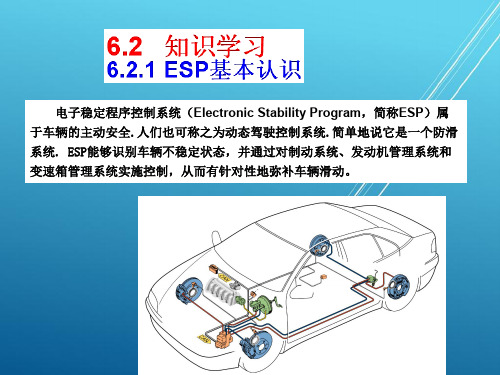
电子稳定程序控制系统(Electronic Stability Program,简称ESP)属 于车辆的主动安全.人们也可称之为动态驾驶控制系统.简单地说它是一个防滑 系统. ESP能够识别车辆不稳定状态,并通过对制动系统、发动机管理系统和 变速箱管理系统实施控制,从而有针对性地弥补车辆滑动。
ESP是在大众、奥迪、奔驰车型上使用此简称。在其它车型上,相同 或相近功用的系统采用了不同的名字。如:
汽车电控系统工作原理

汽车电控系统工作原理
汽车电控系统是现代汽车中至关重要的一部分,它负责监控和控制车辆的各种功能,以确保车辆的安全性、性能和燃油效率。
汽车电控系统包括发动机控制单元(ECU)、变速器控制单元、刹车控制系统、空调控制系统等。
这些系统通过传感器和执行器之间的信息交换和控制来实现汽车的各种功能。
汽车电控系统的工作原理可以简单概括为以下几个步骤:
1. 传感器采集数据,汽车上安装了各种传感器,如氧传感器、车速传感器、油门位置传感器等,它们负责监测车辆的各种参数,如发动机转速、车速、油门开度等。
2. 数据处理,传感器采集到的数据被送往发动机控制单元(ECU)等控制单元,这些控制单元会对数据进行处理和分析,以确定最佳的控制策略。
3. 控制执行器,根据处理后的数据,控制单元会向执行器发送指令,比如调整发动机点火时机、喷油量、变速器换挡等,以实现最佳的动力输出和燃油效率。
4. 反馈控制,在执行器执行指令后,传感器会再次采集数据并反馈给控制单元,以便对控制策略进行调整和优化。
通过这样的过程,汽车电控系统可以实现对发动机、变速器、刹车等关键部件的精准控制,以确保车辆的性能、安全性和燃油效率。
同时,汽车电控系统也为汽车后续的智能化发展提供了基础,例如自动驾驶技术的实现离不开先进的电控系统。
总的来说,汽车电控系统的工作原理是通过传感器采集数据、控制单元处理数据、执行器执行指令和反馈控制的循环过程,以实现对车辆各种功能的精准控制和优化。
这一系统的不断创新和发展将为汽车行业带来更多的便利和安全性。
2013款奔驰A200说明书

2013款奔驰A200说明书
一、中控按键
1、车身电子稳定系统(ESP)
有效防止车身侧滑、甩尾等失控情况,一般情况不建议驾驶员手动关闭。
2、驻车雷达/影像
通过图像以及报警音,警示周围的障碍物。
3、自动驻车
不用脚部一直踩着刹车,系统会自动锁住车轮。
踩下油门即为触发解锁车轮,此时又能继续行驶了。
4、自动启停
红绿灯路口,短暂将发动机熄火。
一旦脚部离开制动踏板,发动机重新着火。
5、内/外循环
内循环指车内空气封闭循环,外循环是车内外的空气交换更替。
一般在拥堵或者外界空气环境不好的情况下打开内循环。
高速时每隔一段时间要切换成外循环换换气,以防空气不新鲜而造成健康问题。
6、温区同步
温区同步功能,改变主驾驶位的温度,其余几个温区也会进行同步的变化。
关闭此温区同步后,每个分区可以自行个性化的设置,满足不同位置乘员需要。
二、车门按键
奔驰A200L驾驶员车门处:
①车窗锁止按钮。
②车窗一键升降控制开关。
③外后视镜的调节开关(角度调节,折叠功能)。
④中控锁按键。
三、车顶按键
①天窗开关。
②主驾驶阅读灯。
③副驾驶阅读灯。
④迎宾灯。
⑤车内灯光控制。
⑥信息咨询。
⑦求助。
汽车电控系统工作原理与结构

汽车电控系统工作原理与结构汽车电控系统是指用电子技术控制汽车运行和操作的系统。
它是汽车电子技术的重要应用,通过精确控制发动机、传动系统、制动系统、灯光系统等汽车的相关部件,提高汽车的性能、安全性和舒适性。
本文将从工作原理和结构两个方面,详细介绍汽车电控系统的相关知识。
一、工作原理1.传感器感知:汽车电控系统通过传感器感知车身的各种物理、化学和电学参数。
例如,氧传感器能够感知排气中的氧含量,进而判断发动机的燃烧情况;油温传感器能够感知发动机的油温,从而为油路提供适当的油量和油压。
2.信号转化:传感器将感知到的参数转化为电信号,从而为后续的电子元件处理和传输提供基础。
例如,氧传感器将氧含量转化为电压信号,通过电缆传输给电控单元。
3.信号处理:电控单元作为汽车电控系统的核心部件,接收各个传感器传来的电信号,进行数字化处理,计算各参数的值,并根据预先设定的控制策略制定相应的控制命令。
例如,在发动机控制方面,电控单元根据氧传感器的信号计算空燃比,再根据设定的控制策略调整喷油时间和量。
4.执行器控制:执行器根据电控单元发送的控制信号,控制相应部件的工作状态。
例如,喷油器根据电控单元的命令,调节燃油的喷入量和喷射时间,从而实现发动机功率和排放控制。
二、结构1.感知系统:感知系统由各种传感器组成,用于感知控制参数。
例如,汽车发动机控制系统常用的传感器包括氧传感器、油温传感器、速度传感器等。
2.信号调理系统:信号调理系统用于将传感器感知到的信号进行处理和转化。
例如,模拟信号经过模拟电路处理后,转化为数字信号,再传输给电控单元进行处理。
3.控制器:控制器是整个电控系统的核心部件,负责接收和处理感知到的信号,并根据设定的控制算法制定控制策略。
控制器一般由微处理器和相应的存储器组成。
4.执行器:执行器根据控制器的命令,控制汽车各个部件的工作状态。
例如,喷油器根据控制器的控制信号,调整喷油时间和量;制动系统根据控制器的信号,调节制动力度。
奔驰电子感应式主动制动系统(SBC)介绍与相关匹配操作

奔驰电子感应式主动制动系统(SBC)介绍与相关匹配操作元征软件 奔驰开发工程师 詹伟 奔驰轿车采用了先进的SBC(Sensotronic brake control)感应式主动制动系统,它集ABS、ASR、ETS、ESP及BAS功能于一体,属于主动安全系统,可以称得上是汽车制动技术史上的一次革命。
感应式主动制动系统(SBC)是一个电子液压制动系统,也称作线传制动,较之其他制动系统,该系统的技术更为先进。
踏板和制动液贮藏罐之间的连接不是机械或液力,而是电子的,好处是每个车轮都可以被单独制动,从而确保急刹车时不会跑偏和丧失附着。
即使是在颠簸不平的路面,不管驾驶员使多少劲儿踩踏板,它都能在紧急情况下实施并保持最大制动力。
当车辆上安装了SBC系统后,将表现出如下更多的优点:①提高了制动压力传递的准确性和灵敏性。
②缩短了紧急制动时的制动距离。
③提高车辆行驶时的安全性。
④使得制动摩擦片的磨损更为均匀,延长了它的使用寿命。
⑤在车辆转弯制动时能够产生更为理想的制动效果。
⑥使车辆行驶更加安全和舒适。
当需要操作与维修底盘及相关刹车零件前,为安全起见,必须先解除SBC系统的制动功能(SBC系统有"预先检测系统"功能,此系统会将刹车系统作用一次),系统检修完毕后,再重新启动SBC系统制动功能,否则SBC系统会产生故障,并发出行驶危险的警示信息。
对该系统(SBC)的解除和重新激活必须借助诊断设备通过对该系统控制模块的控制来进行。
下面就简要介绍如何利用元征X431诊断电脑对奔驰感应式主动制动系统(SBC)进行匹配的操作方法。
进入SBC系统显示如图1所示的功能主菜单,选择“控制单元编码”功能,进入图2所示的子功能菜单。
图1 图21.解除辅助制动系统“SBC”。
选择图2所示菜单的第一项:“解除辅助制动系统”,X431会提示相关的安全说明,见图3,请仔细阅读并遵照执行。
点“是”确认后,提示测试顺序,如图4所示。
奔驰MB.OS系统介绍

QNX OS
AUTO SAR Classic
音频固件 硬件配置
虚拟机
微控制器 抽象层
驱动程序
信息安全
软件底层
4
二、底层架构 - 智慧云
奔驰MB.OS所有功能可通过奔驰智慧云实现互联,有可扩展性、灵活性和可持续性的优势,也可以保护和 使用授权着的数据;
奔驰Me ID:MB.OS以数据驱动提高产品力和用户参与度,到2025年将拥有1600万辆数据用于持续改进;
奔驰MB.OS系统介绍
2023.3
1
一 概述
目录
二 底层架构 三 移动生活空间
四 总结
2
一、奔驰MB.OS系统 – 概述
2023年2月,奔驰发布整车操作系统MB.OS,搭载在MMA模块化架构平台上推出,预计2025年正式上市; 由奔驰自主设计和研发,包含底层技术和用户体验,覆盖芯片到云端、可扩展的全新专属架构,技术实现软
奔驰希望通过自研OS掌握打通智能汽车生态的核心能力,从基础架构层面实现软硬解耦,基于场景联动全 面打通车辆功能,包括信息娱乐、智能驾驶等;应用更多元,打造移动生活空间;形成面向智能汽车产品的 架构能力;
个性化 极致体验
优质内容 (合作伙伴提供)
领先 自动驾驶水平
智能、无缝 驾驶与充电
服务导向 芯片到云端架构
硬件解耦,注重底层安全和隐私保护,以及全场景用户体验;
底层架构
芯片到云端 可扩展
软硬件解耦 安全和隐私 对合作伙伴开放
移动生活空间
身体舒适 - 个性奢侈体验 信息娱乐 – 最佳内容和区域热点
自动驾驶 – 时间的礼物 驾驶&充电 – 智能、无缝衔接
3
二、底层架构 - 硬件&软件
- 1、下载文档前请自行甄别文档内容的完整性,平台不提供额外的编辑、内容补充、找答案等附加服务。
- 2、"仅部分预览"的文档,不可在线预览部分如存在完整性等问题,可反馈申请退款(可完整预览的文档不适用该条件!)。
- 3、如文档侵犯您的权益,请联系客服反馈,我们会尽快为您处理(人工客服工作时间:9:00-18:30)。
ME continuously checks the signal from B2/5 for limit values, if: • Lower limit - Min. 16 kg/h, if throttle angle > 14o • Upper limit - ~ 50-900 kg/h, rpm compared to throttle angle • more then 5 seconds Then after two consecutive driving-cycles: NOTE: Will substitute values if fault is recognized.
18
0V
CMP Signal
2001
111 & 137 Engines
0O
720O
5v or 12V
0V
1440O
19
Synchronizing
Cylinder 1 recognition 111, 137
20
PO341
ME continuously checks the signal if: • No signal within 2 engine revolutions or • More then 1 signal per engine revolution Then after two consecutive driving-cycles:
3
Power Supply
K40/7 - Fuse & relay module (215, 220) (Right SAM) N16/1 - Base module (129, 140)
N3/...
F1 -Fuse & relay module (163)
N10/1 - LF SAM (203)
16
PO335
ME continuously checks the signal if: • (60 - 2 teeth) - 1 tooth • (60 - 2 teeth) +1 tooth • for more then 5 seconds Then after two consecutive driving-cycles:
5
Fuel Management
Inputs: • Coolant temperature sensor (B11) • Intake air temperature sensor (B17 or IAT) • Crankshaft position sensor (L5 or CKP) • Camshaft position sensor (B6/… or CMP) • Hot film mass air flow sensor (B2/… or MAF) • Oxygen sensor (G3/… or O2S)
14
Adaptation
RPM
1750 22 2450 3300 4300 5300 5950 6250
L o a d
L1 L2 L3
34 60 100 %
n1 N1 N2 N3 N4 N5 N6
Load range L2 and speed range 1 must be adapted first then ME-SFI will adapt the other segments automatically.
15
Adaptation
RPM
1750 22 2450 3300 4300 5300 5950 6250
L o a d
L1 L2 L3
34 60 100 %
n1 n1 n1
n2 n2 N3 N4 N5 N6
N1 N2
If the misfire occurred at L2 and speed range 2 be sure that Fly-Wheel is adapted to that point before returning vehicle to owner.
2
ME Tasks
• Control individual injector opening time • Mixture control • start, post-start, warm up • acceleration enrichment • decel shutoff • Injector shutoff • inertia fuel shutoff • ignition faults • Synchronizing injectors
Reproduction by any means or by any information storage and retrieval system or translation in whole or part is not permitted without written authorization from Mercedes- Benz USA, LLC or its successors. Published by Mercedes- Benz USA, LLC Printed in U. S.A.
TDC Cylinder #1
12
Flywheel Adaptation
Flywheel needs to Adapted if: • Replacing flywheel. • Replacing ME-SFI control unit. • Replacing flywheel sensor. • Replacing engine. • Disconnecting battery. • Replacement of motor mounts
as of 1997 10
Crankshaft Position Sensor
CKP (L5) Inductive sensor Used to determine crankshaft position and speed.
11
CKP Pattern
Missing teeth used for crankshaft position recognition and irregular running.
K40/4 - Fuse & relay module (202, 208, 210 3/97 →)
K40 -Relay module (170, 210 →2/97)
4
ME-SFI Functions
• Fuel management • Ignition control • Electronic Accelerator /Cruise Control • On Board Diagnosis • Drive Authorization System • Tip start • Engine cooling fan
3.4V (3090 Ω) 2.9V (2000 Ω) 2.4V (1330 Ω) 1.9V ( 900 Ω) 1.5V ( 630 Ω) 1.2V ( 440 Ω) 0.9V ( 320 Ω) 0.5V ( 170 Ω)
8
PO115
ME continuously checks the signal for limit values, if: • > 80 k Ω (approx. -39OC) • < 45 Ω (approx. +170OC) • or the temperature change after start is not plausible Then after two consecutive driving-cycles:
17
Camshaft Position Sensor
CMP (B6)
1-Ground 2-output signal 3-Power
Hall effect sensor
1440O
0
O
720O
12V
Used for recognition of cylinder # 1 compression stroke Note: 5v on 112,113 engines
24
O2 Sensor
Purpose: To detect oxygen in the exhaust 1. Wiring to ME 2. Vented sensor housing 3. Protective tube The number of sensors on a vehicle will vary with application.
NOTE: IF a fault is present, a substitute value is used to operate the vehicle.
9
Intake Air Temperature Sensor
B17 Also a NTC type of sensor. Primarily affects ignition timing. IAT
13
Adaptation
RPM
1750 22 2450 3300 4300 5300 5950 6250
L o a d
L1 L2 L3
34 60 100 %
n1 N1 N2 N3 N4 N5 N6
There are 6 RPM speed ranges, N1 to N6 and 3 load ranges L1 to L3.
6
Coolant Temperature Sensor
B11/… Negative Temperature Coefficient Resistance decreases as the temperature rises.
7
NTC Sensors
20OC = 30OC = 40OC = 60OC = 70OC = 80OC = 90OC = 100OC =