冲板流量计样本
冲板流量计原理

冲板流量计原理冲板流量计是一种普遍使用的流量计,广泛应用于各种行业,如化工、生物制药、食品、水处理等领域。
本文将从原理的角度讲述它的工作流程。
1. 基本原理冲板流量计基于万斯帕流量计原理,通过利用介质在进出口处产生的压力差和不同位置处转角板离心力的作用,实现对流量的测量。
2. 流程(1) 测量流体进入进口前,测量区域中的流体通过同心的叶轮和模型叶片向下加速,形成高速旋转的涡形流;(2) 流体通过进口后,在物体上形成绕流处理。
叶轮和模型叶片的转动使得进入压力被分配到圆环上,从而形成实质上的等边三角形排列,最终进入涡形流;(3) 进入涡形流后,流体旋转体会改变,流速也会增加,从而形成一个涡大涡小的环境。
当流口变窄时,涡的大小也会发生改变,这产生的压缩效应和涡型叶片的离心力结合起来,进一步产生巨大的压差。
(4) 流口变窄后,流体通过转角板,改变了方向,流速变成了一个更高的数值。
在这里,由于缩窄的限制,流速的增加会导致压力下降。
(5) 安放在转角板上的管端鼓励气阀放在低压区域,可以不受任何干扰地记录起来。
(6) 利用压缩的压差与流速之间的关系,可以根据流口压差的变化推导出流量计。
3. 使用注意事项冲板流量计虽然能够适应许多工作环境,但在使用时还是有些注意事项需要注意。
(1) 测量区的位置要放在流量计前面的直管段中,管道的各种工艺管路接头要保持良好的通畅;(2) 液体的脉动大小和频率要控制在一定的范围内;(3) 在测量气流时,要注意保持传感器的灵敏度。
总之,冲板流量计的原理比较简单,但在实际应用中需要注意细节。
只有在正常使用和维护的情况下,才能充分发挥它的作用。
冲板固体流量计原理

冲板固体流量计原理冲板固体流量计是一种常用的用于测量固体颗粒流量的设备。
它利用冲板原理对固体颗粒进行测量。
下面将详细介绍冲板固体流量计的原理及其工作过程。
冲板固体流量计的原理基于固体颗粒在管道中的流动特性。
当固体颗粒通过管道时,由于惯性和重力的影响,颗粒会产生一个冲击力,使得颗粒在管道中沿流动方向上的速度产生突变。
这个速度突变会引起管道内的压力变化。
冲板固体流量计利用这个原理来测量固体颗粒的流量。
冲板固体流量计通常由一个管道和一个冲板组成。
冲板置于管道内,固定在一定位置上。
当固体颗粒流过冲板时,颗粒会受到冲板的阻挡,使得颗粒在冲板前方形成一个高速区域和一个低速区域。
高速区域的颗粒速度较快,低速区域的颗粒速度较慢。
通过测量两个区域的压差,可以得出固体颗粒的流量。
通常情况下,冲板固体流量计会在冲板前方和后方分别安装压力传感器或差压传感器。
这些传感器将测得的压差信号传输给流量计的控制系统,并经过处理后转化为流量值。
冲板固体流量计的工作过程如下:1. 固定冲板位置和管道尺寸:首先,需要确定冲板的位置和管道的尺寸。
这些参数是冲板固体流量计的重要参数,会直接影响测量的准确性。
2. 安装传感器:根据冲板的位置,安装压力传感器或差压传感器在冲板前方和后方的管道上。
这些传感器将用于测量两个区域的压差。
3. 信号传输和处理:传感器测得的压差信号将传输给流量计的控制系统。
控制系统会对信号进行处理和转化,得出固体颗粒的流量值。
4. 测量结果显示:最后,测量结果将显示在流量计的显示屏上或通过其他输出方式呈现给用户。
总结起来,冲板固体流量计是一种通过测量固体颗粒在管道中的速度突变和压差来测量固体颗粒流量的设备。
它的原理简单且可靠,广泛应用于各种领域的固体颗粒流量测量。
冲板使用说明书
防
尘
测量范围 0~500kg/h 0~40t/h 40~400t/h
不变 结构防尘 不变 结构防尘
3. 二次仪表 3.1 环境温度:-20℃ ~ +60℃ 存放温度:-40℃ ~ +75℃ 3.2 供电电压:交流 220V±10% 50Hz 功率消耗约 8W 3.3 数字指示:6 位 LED 数码显示数值 3.4 模拟输出:电流输出 4 ~ 20mA,负载电阻小于 500Ω ,或电压输出 1 ~ 5V, 负载电阻大于 10KΩ (可选的) 3.5 测量范围:0 ~ 75kg/h 或 0 ~ 400t/h 3.6 测量精度:在全量程内优于 0.5% -2-
图九
-8-
中国 大连智高仪器有限公司
China Dalian zerogo instrument co.,ltd
地址:中国 大连市甘井子区玉胜路 1 号 1-1 邮编: 116038 电话:0411-86100723 13804098210 传真:0411-83897310 E-mail:cx090530@ 361688087@
2.1 接线图 (见图八)
图八 2.2 接线端子 1.20—电源 AC220V 2.3.4—累积流量继电器输出 (2.3 常开,3.4 常闭) 5.6.7—报警输出继电器输出(可选) (5.6 常开,6.7 常闭) 8—ANG 仪表公共地 (12.13)-1~5V DC 输出,12 正 13 负 (12.14)-4~20mA 输出,14 正 12 负 (15.16)-信号输入,15 正 16 负 17.18.19—定量控制输出(可选) (17.18 常闭, 18.19 常开) 所有继电器负载能力最大为交流 250V0.5A 2.3 按键功能 (见图九) S—设定键。 按 S 键可以进入参数层, 这时数字将 出现闪动,只有这时才能按动相应的键进行参数 修改,然后再按 S 键进行设定数据的确认。 R/L—数字左右移动, 在修改参数时, 可以按 R/L 键至所要修改的数据,然后进行修改。 M—状态显示,按 M 可以依次显示状态值。 A—数字增减。在修改参数时可以按 A 键增减数字,最后按 S 键确认。 按仪表 M 键显示状态栏,共有四层: 小窗口显示:0 小窗口显示:1 小窗口显示:2 小窗口显示:3 大窗口:显示累积量,单位根据脉冲价而定 大窗口:显示流量百分比,即瞬时流量除以仪表量程再乘以 100% 大窗口:显示瞬时流量,单位:Kg/h 大窗口:显示采样频率(HZ) ,仪表自动检测
冲板流量计的安装和使用
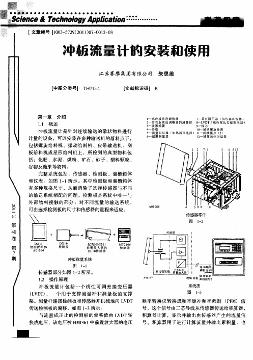
物料下落高度 h06m ( =. 5 即物料下落前位置到 检测板 中心位置的高度差) 检测板与水平方 向夹角 仅 为 8。 5 物料冲向检测板 时与水平方 向夹角 B为 6 。 0 物料冲向检测板时与检测板夹角 为 3 。 5
、
f
、
强豫 ■
,
其中:f = m 检测板上测得的垂直压力 ( 牛顿)
q m=流量 (l t1 /)
h 下落的高度 ( = 初始速度应为零)
=
检测板与水的夹角 (传感角度) y = _ 下列例子表明了如何计算非标准状态的压力 :
一
。 .
. 恒
J | }
黥
一 一 ● . ¨
● ●
● ●
●
●
●
标准条件
图 14 —
1 . 非标 准 使用 条件 .2 2
在非标准使用条件下 ,检测板传递给 位移检 黼 测传感器 的压力可 以通过计算得 出 ,在计算 的基 一 础上可以选择 出合适量程的传感器。 下列的式子用于计算所测量的压力范围:
F = m×、 ho2 )XSn ×Sn^ mq / (.5 i iy
通 过转换 信号 的电缆 向前 置放大器 和 L D V T提供 电源供应 。 1 . 标准使用条件 .1 2
冲板 流量 计测 量 的流 量 范 围从 0到最 小 的 1t ./ 最 大 80/ 多 种 测量 范 围 ,这 些 范 围要 5 h和 0t h共 求检测板 的机械安装要在 以下 的标准条件 ,如图
冲板流量计介绍范文

冲板流量计介绍范文冲板流量计的基本原理是根据爱维思方程,通过测量装置的压力变动确定流量。
冲板流量计的主要组成部分包括测压装置、流量计直径、进口管道、出口管道等。
在测量过程中,流体进入冲板流量计后,流体受到冲板的阻碍,从而加快流体的速度和压力,进而导致测压装置上的压力变化。
根据测压装置上的压力变化,可以推算出流体的流量大小。
冲板流量计具有简单的结构和易于安装的特点。
冲板流量计通常由金属板制成,形状为正方形或圆形,与进口管道和出口管道连接,通过螺栓固定在管道上。
冲板流量计还配备有测压装置,测量装置可以是压力传感器、压力开关等。
冲板流量计还可以根据需要安装温度和压力传感器,以实时监测流体的温度和压力。
冲板流量计的工作原理主要是通过测量压力变化来确定流量。
当流体通过冲板流量计时,流体将受到冲板的阻碍,从而加速流体的速度和压力。
流体通过冲板后,速度和压力恢复到正常状态,从而导致测压装置上的压力变化。
通过测量装置上的压力变化,可以推算出流体的流量大小。
冲板流量计的测量精度主要受到流体的粘度、温度、压力等影响。
冲板流量计具有多种优点,适用于不同的流体测量。
首先,冲板流量计具有简单的结构和低成本,易于安装和维护。
其次,冲板流量计具有较高的精度和响应速度,能够准确测量不同流量范围的流体。
冲板流量计还可以在不同的工作环境下使用,具有较好的耐压和耐腐蚀性能。
最后,冲板流量计还可以根据需要进行多种信号输出,方便实时监测和记录。
然而,冲板流量计也存在一些局限性和注意事项。
首先,冲板流量计对管道的直径和进出口阻力要求较高,需要在设计时进行合理布局和计算。
其次,冲板流量计测量精度受到流体粘度、温度和压力等因素的影响,需要根据具体情况进行校准和调整。
此外,冲板流量计还存在一定的压力损失和能量损耗,对流体系统的能耗也有一定影响。
总结起来,冲板流量计是一种测量液体流量的重要仪器设备,在工业生产中得到广泛应用。
冲板流量计具有结构简单、可靠性高、精度较高等优点,能够准确测量不同流量范围的液体。
冲板流量计说明书讲解

冲板流量计积算显示仪使用说明书(DS—41)大连三协仪器仪表有限公司用户须知操作此系统前,你应首先阅读这本手册。
1.安装环境仪表不要安装在生产现场或具有腐蚀性气体的环境中。
不要靠近动力设备安装。
运行温度:0-40℃相关湿度:低于80%2.布线该仪表与流量计及其它仪表间的布线应远离电力电缆,从而避免仪表受到电磁感应和静电感应。
特别注意,用于流量计的布线应使用屏蔽电缆,并且不受其它电缆的影响。
3.电源仪表的电源供给应与其它仪表分开。
并且在供电时应采用一个电源开关和一个保险丝(2A)来进行保护。
电源: AC 220V±10 % (50/60Hz) 10VA4.清洁时间一长,在面板和盖子上将积聚许多灰尘,灰尘可能导致电源无法接通或不再绝缘。
请定期清洁面板和盖子。
注意打开盖子前,应首先切断电源。
1、概述显示表DS-41给流量计中的差动变压器初级线圈提供励磁电压,同时接收由差动变压器次级线圈产生的信号,并由显示表中的微处理机对这些信号进行运算处理后,显示瞬时和累积流量值。
它还输出瞬时流量的电流信号和累积流量的脉冲信号作为输出信号2、输入/输出说明电 源 电 压:AC 220V ±10 %,50/60H Z输 入 信 号:差动变压器信号 正弦波U MAX =7V 2.5KHZ 输 出 信 号:流量输出DC 4~20mA (负载<500Ω) 数字输入信号:正比例值选择信号(二点)零点自动调节信号。
连结方法: (1)、电源在内部每个连结点的电流大约为7.5mA(2)、电源在外部外部电源选择在12~25V 直流电压之间 数字输出信号:流量上限报警流量下限报警累积脉冲输出,脉冲宽度 (信号处于低电平)可调连接方式:负载电流: ≤100mA电压:≤30VDC当负载为电感性时,则如下所示装入一稳压二级管。
13161415+15 VDC14151716V242625LoadLoadV3、外部尺寸括号内部数字表示镶板的开口尺寸 单位:毫米第1页2827电子计算器等5.1K Ω+15VDC144(138)72(68)20301.625支撑固定装置接线盒4、接线序号 连接 序号连接1 差动变压器(红) 17 瞬时流量输出(+)2 差动变压器(绿) 18 瞬时流量输出(-)3 差动变压器(白) 19 +15V4 差动变压器(蓝) 20 比例值选择信号15 差动变压器(黄)21 比例值选择信号1 6 不用 22 零点自动调节信号7 不用 23 OV 8 不用 24 流量上限报警 9 不用 25 流量下限报警 10 地 26 公用(信号发生器) 11 地 27 累积流量脉冲(+) 12 地 28 累积流量脉冲(-)13~16 不用 29~32不用L1 交流电源 ※ :弹簧为拉力类型时,交换白、黄端L2 交流电源地1243567891011121314151617181920212223242526272829303132第2页5、显示表各部分的名称及功能TOTALIZER : 由6位红色发光二级管组成,显示流量的累积值,在PGM 状态下,可以 (累积量) 显示每一个设置值。
冲板式流量计

冲板流量计XST-ILE\XST-LFD系列冲板式(固体)流量计概述:LFD系列冲板式(固体)流量计是一种基于动量原理来测量自由下落的粉、粒状介质的流量计。
它把被测介质的瞬时重量流量转换成标准直流信号(0-10mA或4-20mA)输出,从而可与各种现有仪表配套,对被测介质流量进行指示、积算、记录和控制等操作。
本流量计在密封的条件下对粉、粒状介质的流量进行连续测量。
因此可在化工、水泥、轻工、粮食、电力、采矿、冶炼和港口等领域得到广泛应用。
LFD系列冲板式(固体)流量计特点:1:流量计在水平状态下垂直力不影响仪表零点及精度,故不会因捡测板物料粘结而出现零点漂移。
2:流量计对测量产生的非线性误差具有修正能力。
3:流量计只有检测板与物料直接接触,最大位移量为2mm,故流量计本身没有易损件,维护量极小。
4:流量计具备有自动定量控制和超流量报警和串行接口输出,可用于集中控制。
LFD系列冲板式(固体)流量计主要技术参数:1:允许粒重、直径:检测板重量的6%、ф50。
2:测量范围:0-25t/h;0-300t/h.3:介质温度:≤200℃。
4:环境温度:-20~60℃。
5:精确度:土0.5~1%。
6:输出电流:0/4~20mA,RL<700Ω7:继电器控制输出:AC220V/3A,DC24V/5A,阻性负载。
8:电源:220V.AC.50HZ5W。
DE10型和DE20型系列固体冲板流量计DE10和DE20型冲板流量计是融合了几十年来从事动态称重的丰富经验而特殊设计的。
专用于连续测量粉状,颗粒状等散状物料的瞬时流量及总累计量。
广泛适用于化工,建材,冶金,电力,煤炭,烟草等行业生产工艺过程的控制。
冲板流量计可以方便的安装在多种输送机的落料点下,包括螺旋给料机,振动给料机,皮带输送机,刮板输送机,风力输送系统或星形给料机上,所监测的典型物料包括:化肥、水泥、焦炭、矿石、沙子、木屑、塑料颗粒、谷物、马铃薯片、大米等糖果等物料。
6-1,FH5377gb-dlm oprating manual(冲板流量计操作手册)
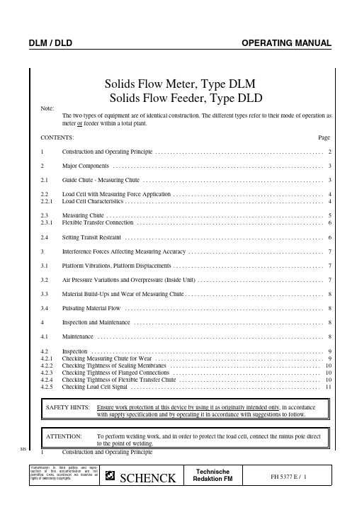
325Solids Flow Meter,Type DLM Solids Flow Feeder,Type DLDNote:The two types of equipment are of identical construction.The different types refer to their mode of operation as meter or feeder within a total plant.CONTENTS:Page1Construction and Operating Principle ........................................................22Major Components ......................................................................32.1Guide Chute -Measuring Chute ............................................................32.2Load Cell with Measuring Force Application ..................................................42.2.1Load Cell Characteristics ..................................................................42.3Measuring Chute ........................................................................52.3.1Flexible Transfer Connection ..............................................................62.4Setting Transit Restraint ..................................................................63Interference Forces Affecting Measuring Accuracy .............................................73.1Platform Vibrations,Platform Displacements ..................................................73.2Air Pressure Variations and Overpressure (Inside Unit)..........................................73.3Material Build-Ups and Wear of Measuring Chute ..............................................83.4Pulsating Material Flow ..................................................................84Inspection and Maintenance ...............................................................84.1Maintenance ...........................................................................84.2Inspection .............................................................................94.2.1Checking Measuring Chute for Wear ........................................................94.2.2Checking Tightness of Sealing Membranes ..................................................104.2.3Checking Tightness of Flanged Connections .................................................104.2.4Checking Tightness of Flexible Transfer Chute ...............................................104.2.5Checking Load Cell Signal ...............................................................11SAFETY HINTS:Ensure work protection at this device by using it as originally intended only,in accordance with supply specification and by operating it in accordance with suggestions to follow.ATTENTION:To perform welding work,and in order to protect the load cell,connect the minus pole direct to the point of welding.1Construction and Operating Principle325The represented equipment construction is suited for measuring the reactive forces generated by the feed material when "flowing"over the measuring chute.If the total of all mass particles of material on measuring chute are concentrated in point »M«,forces F G +F V +F RV are decisive for flow rate acquisition.Thus,only the totals of the vertically acting force components are applied to the load cell via the scale lever mounted in crossed flexure strips »D«.Location of point »M«and thus lever length »L M «do not only depend onmeasuring chute geometry but also on flow rate,friction and bulk density.In place of lever length »L M «,order-specific TECHNICAL DATA indicate device constant »GK«which already comprises the load on load cell per kg/h flow rate.Guide chute Feed Material Q NENNGK =--------P NENN kg ----Inspection coverkg/hQ NENN =Load on load cellMeasuring Chutewith P NENN ,without tare P NENN =Nominal flow rate F =Normal force of deflection pulse F R =Friction forceF F =Force of deflection =Check weight pulseLoad cellto be providedF H=Horizontal forceby user,if need be Load On Load CellCounter weight Through Check Weighton scale lever The check weight is not used for for preload scale calibration but for check on load cellof elements on load cell used for measuring force application to load cell.For this reason,value of load Q PRF check weight Cable Q P actually acting on load cell junction cell has to be entered.right/left depending on orderL PGQ PRF =Q P ------L WZkgFlow rate display reads:Q PRFP(Q PRF )=------GKkg/hVIEW A3252Major Scale Components2.1Guide chute -Measuring chute -Scale leverGuide chuteScale flangeGuide chute,measuring chute and scale lever come set to one another.In case of maintenance,please observe the following hints:o Check to see if dimensionX =1to 2mm and Y =approx.8mm.Y dimension results if youa)Align scale lever horizontally,or //2mm to housing flange A by using set screw of measuring force application to load cellb)Set guide chute with its scale flange todimension X within slot range V .Always reset measuring chute top edge to guide chute by dimension X .Load cellCounter nutKey width 17mm Measuring force application to load cell with set screw M10,hexagon socket 5mm ,accessible from below through scale leverScale leverHousing flange Spirit level D =crossed flexure strip axleATTENTION!!Before you remove scale lever,first remove load cell for protection.3252.2Load Cell with Measuring Force ApplicationRepresentation below shows measuring force application to load cell with cover removed.The ball applies the measuring force to load cell from below.During repairing,thoroughly adjust overload protection to nominal measuring displacement H of load cell type used.In plant operating state,transit restraint must be opened for scale working.See also Installation Manual FH 5376/8.Overload protection displacement H adjusted with feeler gauge but with out working tare load.Hexagon socket 3mmCounter nut M6Load cellBellows BallTransit restraintScale lever Provide air gap for operationIMPORTANT When setting overload protection,ascertain that load cell bellow is not deformed.NOTE!!This would make load cell unsuitable for use.2.2.1Load Cell CharacteristicsDepending on nominal flow rate /scale type,load cells of HOTTINGER BALDWIN MESSTECHNIK GmbH are used with rated capacities of 10kg /20kg or 50kg.Type designation and rated data are inscribed on load cell type plate.Basic load cell characteristics:Load cell typeRated Capacit y Nominaldisplacement »H«+15%Rated load Nom.charac.Load limitSee type plateSee type plate (mV/V)150%of rated capacity Z6H2Z6-4Z6-410kg 20kg 50kg0.3mm 0.29mm 0.27mmNote:The load limit value applies in conjunction with effectively set overload protection of scale.Protected to:IP 67Nominal temperature:-10b C to +40b C Service temperature:-30b C to +70b C Reference temperature:+22b C Cable length:3,or 4,m3252.3The Measuring ChuteDepending on properties of material to be weighed,measuring chute design can use the following materials:Material PropertiesChute MaterialWear of measuring chute and/or materialbuild-ups on measuring chute are decisive for the selection of chute material.To our experience,the materials stated in list largely cover requirements.If,after all,performance is not satisfactory,please contact SCHENCK to advise you about a solution effected,e.g.through modification of -Grain-size spectrum and/or-Material moisture and/or-Material temperature.An analysis of the material to be weighed might show you the cause of build-up.Slightly abrasive Slightly adhesive Prone to static charge Polished stainless steelSlightly abrasive Slightly abrasiveNot prone to static charge PTFE (TEFLON)More heavily abrasive Slightly adhesive Prone to static chargeManganese steelAscertain that distance between guide chute and measuring chute is the same on either side.tubularcross-memberFlangeConnecting strut to scale leverHose Sealing clamp flange Scale with phasehousingDismantle sealing membranes To remove measuring chute,unscrew the 4fixation screws M10.for replacement of scale leverto enable membranes to be drawn over over the flanges of the tubular cross-member.NOTE!!As a rule,use new spring washers or self-locking nuts.Torque of each screw =30Nm First mount scale lever and tubularcross-member,then align sealing membranes free of torsion,mount them on scale housing with sealing flange (phase against sealing membrane)and attach to tubular cross-member by using a hose clamp.NOTE!!Before dismounting scale lever,first remove load cell for protection.2.3.1Flexible Transfer ConnectionIf scale is equipped with flexible transfer connection,ensure tightness of EXPANDED RUBBER sealing elementsto transfer connection but avoid heavy friction which may cause wear of sealing elements.Feed headGuide chuteTransfer connection Highly elastic EXPANDED RUBBERSECTION A-B(enlarged)Do not tighten bolts more than e hand lamp tocheck that no gap light is visible.2.4Setting Transit RestraintBefore operating scale,set transit restraint as described below:*Opening transit restraint for operation:Scale lever play requiredin operating state Step3Turn screw loose in direction of arrow.Step4Turn screw in direction of arrow until approx.1mmair gap to scale lever is reached.Also set lower screw(still Step3)to1mm air gap to scale leverand secure the two screws by using counter nuts.Scalelever3253253Interference Forces Affecting Measuring Accuracy 3.1Platform Vibrations,Platform DisplacementsForces resulting from platform vibrations acting on scale can affect its measuring accuracy to a considerable extent.This particularly concerns "slow"vibrations @2Hz with certain speed amplitudes which the electronic evaluation system cannot filter out of load cell signal.Platform vibrations can entail temporar torsioning,also due to inclined position of scale.Torsioning introduced via the guide chute can change material flow at transfer to measuring chute.The above events occuring in operating state can first be evidenced through monitoring of:-Start intervals of vibrators,such as big rotating machines,compressors,mills-Silo levels,wind influence on silo,one-sided exposure to sunlight,etc.-Changes in platform load,e.g.through access.If measures do not become obvious by monitoring,check computationally to see if building effects are conform to installation prerequisite values stated in Installation Manual FH 5376.For further action,please consult SCHENCK.3.2Air Pressure Variations and Overpressure (Inside Meter)Air slideButterfly valveFalse air hoodSolids flow meterDepending on design of pneumatic feed system installed downstream of solids flow meter,return air is generated which must by all means be exhausted below the meter.Provide a dust collection system sized in accordance with appropriate regulations,to ensure that in the operating state the limit values for p =-2mbar to -8mbar and for p <±2mbar within indicated low-pressure range will not be exceeded.Dustcollection Return airPneumatic Avoid overpressure inside meter,which may be evidenced by the egress of dust at the false air hood,by a sufficient outlet area of the butterfly valve and secure valve position after a measurement has shown that the limit values are not exceeded.feed systemPrefeeders of standard design,e.g.air slides,must not be dedusted or vented separately or in addition.3253.3Material Build-Ups on and Wear of Measuring ChuteMaterial build-ups on measuring chute falsify Force F F of the deflection pulse and thus also the vertical force component F V ,decisive as measuring force.oCheck surface of measuring chute at the time of commissioning whenever system is in stop state.-Material build-ups are most likely to occur in the measuring chute lower part where the speed of material is slowest.-Wear is most likely to be noted in the measuring chute central area where the force of deflection pulse is highest.oCheck measuring chute surface also during operation,with material flowing homogeneously over the entire measuring chute area.Normally,material build-ups on measuring chute cannot be detected in operating state.oRemedy as described at Item 2.3.3.4PulsationsA pulsating flow of material over the measuring chute causes a load cell signal associated with vibrations thus reducing its accuracy.With optimized air setting,air slides are perfectly suitable for pulsation-free material flow.Starfeeders should feature overlapping chambers.Vibro-feeders should operate with high frequency.4Maintenance and Inspection GENERAL SAFETY HINTS!!While system is operating,open inspection cover only if both pneumatic feed system and dust collecting system operate faultlessly.Never put your hand into flowing material.There is danger of injury.Never let objects drop into scale.Remove objects dropped into scale from downstream systems when scale is in stop state.There is danger of subsequential damages.4.1Maintenance o Avoid material build-ups on measuring chute as described above.o If dust deposits on scale lever keep recurring,do not remove them because this will change tare weight.oRemove dust deposits in the scale lever area only if deposits might affect scale lever mobility.3254.2InspectionWhen inspecting system,perform inspection work below.SAFETY HINT!!Before performing inspection work,check to see if system is in stop state and interlocked against inadvertent start.Cons.No.Work to be performedMeasured and check variable Equipment and utilities Interval m=Monthly a=AnnuallyComments4.2.1Check measuring chute surface for wearIn accordance with hints below4.2.2Check tightness of sealing membranes 4.2.3Check tightness of flanged connections 4.2.4Check tightness of flexible transfer connection (Option)4.2.5Check load cell signal4.2.1Checking Measuring Chute For Wear o Measure wall thickness of measuring chute bottom and side walls.o Replace measuring chute if wall thickness particularly in the high level stress area is worn down to minimum 2mm (=half wall thickness).oContact SCHENCK,if the measuring chute service life seems inadequate to you.4.2.2Checking Tightness of Sealing Membraneso Check flexibility of sealing membranes visually and manually.See Item2.3,»The Measuring Chute«.Sealing membranes are made of VITON,a material highly wear and temperature resistant and of longlife.o For changing embrittled or untight sealing membranes,see Item2.3.4.2.3Checking Tightness of Flanged Connectionso Avoid egress of dust on flanged connection of scale.o Tighten flange screws on flanged connection concerned.o If resealing fails,retighten flanged connections by using THEROSTAT sealing strings.See Installation Manual FH5376,Section4.4.2.4Check Tightness of Flexible Transfer ChuteIf negative pressure of dust collecting system is correctly set,no dust can egress,not even if there is a small gap.o However,to be on the safe side,check tightness of sealings in accordance with Item2.3.1»Flexible Transfer Chute«.325DLM/DLD OPERATING MANUAL4.2.5Checking Load Cell Signal(Through Skilled Measuring and Control Engineer)NOTE!!Flow meter has to be ready to operate;system,cut off.[%]Load Cell Load Displayo Check signal of load cell measuring load(output signal)in themeasuring range by using check weights.(For load cell ratedcapacity[kg]and characteristic value[mV/V],see load cell typeplate).o Display load cell signal in measuring range(preload compensated).o Place prepared check weights on check weight lever one after theother.o Record load diagram as shown left.Measuring point connection should form a straight line.[kg]In case of grave deviations from straight line,continue checking asunder:Preload Check WeightDeviation in measurement may be due to-Defective load cell-Damaged parts of measuring mechanism.o Remove load cell and check visually-Load application surface for dirt traps-Bellows for deformation.o Check parts of load application into load cell,see pp.3,4.-The ball in the set screw socket must not have any flat spot.-Scale lever must be aligned parallel to device flange.If there is a deformation of scale lever,dismount lever and try to align.NOTE!!Before dismounting scale lever,loosen flexible sealing membranes for protection.See Item2.3!325。
- 1、下载文档前请自行甄别文档内容的完整性,平台不提供额外的编辑、内容补充、找答案等附加服务。
- 2、"仅部分预览"的文档,不可在线预览部分如存在完整性等问题,可反馈申请退款(可完整预览的文档不适用该条件!)。
- 3、如文档侵犯您的权益,请联系客服反馈,我们会尽快为您处理(人工客服工作时间:9:00-18:30)。
DC-40
在线连续计量物料流量-DC 系列冲击式散状固体流量计
(简称冲板流量计)
型冲击式散状固体流量计可在线测量散状物料的流量。
测量范围
二次仪表
二次仪表可选择DHA(国产),SF500(德国西门子)。
冲板流量计原理与结构
该产品遵循牛顿第二定律原理,由流量计内的位移传感检测出与瞬时流量相对应的位移信号传送给显示仪表,显示并输出瞬时流量和累计流量等。
可测物料
粉状体(塑料原料、铁粉、硫酸钠、水泥、维生素、可可、氧化铝、铁矿石粉、青铜矿、煤粉、碳黑、氰酸钾、面粉),粒状体(各种谷物、盐、各种肥料、饲料、
小麦、砂糖、玻璃细珠、橡胶屑),片状体(石棉、玉米片、烟草),块状体(合成橡胶、镁矿石、铝矾土、石灰石),浆料(精铜矿浆、预拌混凝土)。
DHA 流量积算仪
DC-200。