检波器单元测试(Geophone element testing)
accuseis sl11数字检波器工作及测试原理
系统的测试指标及其测试原理。
关键词数字地震勘探采集系统数字检波器 AccuSeis SL11测试项目
Yan Wei, Li Zhengzheng, Li Zhengran, Gao Fengwan and Yan An. Working and testing principle of AccuSeis SL11 digital geophone. EGP,2019,29(4) :214-217
1数字检波器的方向和极性
对于AccuSeis数字检波器而言,其核心部件为 微机电系统(MEMS, Micro Machined Electro Mechanical System)加速度传感器,作用为拾取垂 直分量的地震波能量,并依照设置的采样率实时输 出加速度数值。数字检波器会通过测量的重力自动 计算倾斜角度,当倾斜角度超过20°时,数字检波器 会将错误信息以标识的形式发送至中央记录系统。
样可配用Firefly无线系统、Hawk节点系统并能在 iXl平台下使用G3i数字地面设备⑵o 2018年 BGP在中东某国执行了设备占用量23.4万道,实时 采集18.6万道的纯数字采集项目,项目应用了 AccuSeis(SLll)单分量数字检波器及iXl平台下的有 线数字采集设备。下面以AccuSeis检波器为例,说 明其工作原理及厂家配套的测试项目和测试原理。
岩 巍等:AccuSeis SL11数字检波器工作及测试原理
215
竖直坐标轴的方向与矢量的方向指向加速度的正方 向,即检波器受到向上的力时,输出极性为正的加速 度数值。此外,由于核心部件MEMS为水平焊接的 PLCC (Plastic Leaded Chip Carrier 塑封有引线芯 片载体)封装方式芯片,且安装MEMS芯片的传感 器板与搭载控制电路的主板采取插座方式连接 ,首 先从物理结构上杜绝了模拟检波器安装或焊接造成 的反相现象⑷。
五种地震检波器

五种地震检波器地震检波器是一种将机械振动转换为电信号的地震勘探专用振动传感器,是槽波地震勘探仪器中接收地震信号的个器件,它的性能会影响地震勘探结果。
煤矿井下地震信号的信噪比较低、波形场复杂、地震勘探条件复杂,因此研制针对于槽波地震勘探的检波器非常重要。
实际勘探中应用为广泛的地震检波器为动圈式地震检波器。
随着技术和方法的不断创新,检波器类型越来越丰富。
我国开展了许多针对地震检波器的应用研究和试验工作,研究了三分量MEMS地震检波器、光学地震检波器、压电式地震检波器、电化学地震检波器等新型检波器。
1、动圈式地震检波器根据资料显示,大部分槽波勘探都是使用动圈式地震检波器,它属于速度型地震检波器。
在使用动圈式地震检波器进行槽波地震探测时,经常检测到一种频率为400Hz 的形似自激振荡或感应干扰的现象。
经研究发现,它是由于两分量速度检波器中检波器芯体的高频谐振引起,术语称之为检波器二次谐振。
速度检波器的二次谐振属于机械谐振范畴,二次谐振现象在各种型号的动圈式地震检波器产品上都存在。
对于精度要求较高的槽波地震勘探而言,这种高频谐振就变得十分有害而不容忽视。
对于检波器的二次谐振现象,可以改用加速度检波器芯体,这样可以从根本上解决这个问题。
2、光学地震检波器光学地震检波器主要是利用光波敏感元件的特性研制的,根据传感机理的不同可以分为强度调制型、光纤光栅型、马赫–曾德尔干涉型、迈克尔逊干涉型、萨格纳克干涉型、法布里珀罗干涉型、光纤激光型以及光栅型等,各种类型的光纤地震检波器研究取得了不少实验室及实际应用成果。
光学检波器具有灵敏度高、安全可靠、频带宽、动态范围大、适应性强等优点。
光学检波器有较强的抗电磁干扰能力,是未来地震检波器有可能采用的主要技术之一。
但光学检波器制作工艺难度大、成本高,目前广泛应用于井下槽波地震勘探尚有难度。
3、电化学地震检波器电化学地震检波器是利用电化学原理,将振动信号转换为电信号的检波器。
近年来,通过技术改进已经成功研制了实用的电化学地震检波器,并实现了产品化。
SMT-200检波器测试仪培训

检波器测试仪的使用一、前言目前在石油地球物理勘探领域使用的检波器有多种,按照工作原理分主要有:模拟速度检波器、模拟加速度检波器、压电检波器和全数字检波器。
为了保证野外使用的检波器的质量,就必须有一种设备能够对检波器的性能进行测试,这种设备就是检波器测试仪。
根据检波器种类的不同,检波器测试仪也有多种种类。
由于现在陆地上使用的检波器主要是常规速度检波器,因此本文主要介绍该种类型的检波器测试仪。
二、常规检波器_测试项目常规检波器的测试项目主要有:自然频率、阻尼、灵敏度、直流电阻、交流阻抗、失真度、极性等。
三、测试原理和方法常规检波器的测试的原理是由检波器测试仪给检波器线圈提供一个脉冲电流,则线圈将会在磁场中运动,就会切割磁力线,产生感生电动势,然后算出阻尼系数、自然频率和灵敏度。
由于检波器测试仪型号的不同,测试方法有所不同,有正向激励(如GT-7XXX、ZSF-300)的,有负向激励(如SMT-100、SMT-200)的,但原理都是一样。
1.频率、阻尼及灵敏度测试对检波器或检波器串加一适当的恒定直流驱动源(相当于该检波器灵敏度的60%~90%,SMT-200大约为70%),待检波器在直流驱动源作用下稳定后,撤去驱动源,采样检波器的响应输出信号并以此时刻为零点,检波器线圈自由振动,输出结果为一逐渐衰减的阻尼正弦波,求出第一次峰值和第二次峰值的大小以及第一次过零点的时间,通过分析检波器的运动方程及已知驱动电流分别算出阻尼系数、自然频率和灵敏度。
2.直流电阻测试测试直流电阻时,可以把检波器视为一个加在运算放大器两端的电阻,若一个恒定的电流连续加在未知电阻R f和已知的参考电阻R i上,测出输出电压V o,利用运算放大器的工作特性可以计算出未知电阻R f 。
检波器的直流电阻是线圈电阻和阻尼电阻并联的值。
3.失真度(畸变)及动态电阻测试失真度测试给检波器加一个高纯度(低畸变)的标准正弦波,在检波器响应的多个周期内,每个周期都采集出一定数量的样点并求出平均值,然后用快速傅立叶变换计算响应波形的基波、二次、三次谐波分量,根据这些值计算失真度。
新型高精度地震检波器
20 0 2年 6月
物 探 装 备
第 1 2卷
第 2期
新 型 高 精 度 地震 检 波 器
李 淑 清
( 津 科 技 大 学 自动 化 系 ,天 津 河 西 区 3 0 2 ) 天 0 2 2
摘
要
李淑 清. 型高 精 度地震 检 波器 . 探 装 备 ,02 1 () l2 18 新 物 2 0 ,2 2 :4 ~ 4
2 4超 级 检 波 器 , 于 1 9 并 9 2年 在 EAEG 巴 黎 展 销 会
— —
线 圈与磁场相对 运动的位移 ;
Z — 每 匝 线 圈 的平 均 长 度 ; — 线 圈与磁场相对运 动的速度 ;
上 参 展 。 特 点 是 畸变 及 其 它 指 标 的 容 差 范 围 更 小 。 其
引 言
式 中 : — — 线 圈 的 磁 通 ( b) W ; Ⅳ—— 线 圈 匝 数 。
随 着 地 震 勘 探 由 构 造 圈 闭 向 非 构 造 圈 闭 的 转 换 , 检 波 器 提 出 了 愈 来 愈 高 的 要 求 。 过 去 的 几 十 对 年 、 别是近 1 特 0年 , 国 内 外 油 气 勘 探 事 业 中 , 国 在 我 的 各 项 配 套 设 备 和 技 术 都 有 了 长 足 的 发 展 。 就 检 波 器 而 言 , 际 勘 探 市 场 陆 续 推 出 了 一 些 技 术 先 进 的 国
新产 品。
当 线 圈 在 恒 定 磁 场 中 作 直 线 运 动 , 切 割 磁 力 并 线 时 , 圈 两 端 产 生 的 感 应 电 势 为 线
, |
Байду номын сангаас
E — N BI
论检波器组合的连接方式
.
( 13)
将式 ( 7)两边取导 数后, 将 式 ( 12) 的一 阶导数 和二 阶
导数代入其中, 得检波器组合的电路方程
d2U dt2
+
2D
0
dU dt
+
2 0
U
=
-S
d2 V dt2
,
( 14)
式中 0 为自然频率; D 为阻尼系数; V 为地表的绝 对振动
速度, 且
0=
k M
,
D=
2
1 0M
LBL (R c +
R
d)
∃
ቤተ መጻሕፍቲ ባይዱ
qS 1
,
(21)
1 D = 2 0M
+ (BL ) 2 [R L + qRd ] qR cRd + RL ( R c + Rd )
合的等效电 路, 推导出检波器组合的 传输特 性 检 波器组 合输出电 压与 检波点 地面 振动速 度的 数学关
系, 依据这一理论, 可 以确定, 采用串联数等于并联数的串并联方式是检波 器组合最佳的电路连接方式。
关键词: 传感器; 地震勘探; 检波器组合
中图分类号 : TP212. 1
文献标识码: A
V=
dx dt
.
+ ( BL ) 2 [ pRL + qR d ] , qRcRd + pRL (R c + R d )
( 15) ( 16) ( 17)
第 7期
孙传友, 等: 论检波器组合的连接方式
15
由式 ( 14)可得检波器组合电路的传输特性
U= V
U( j ) V( j )
第二章 地震检波器
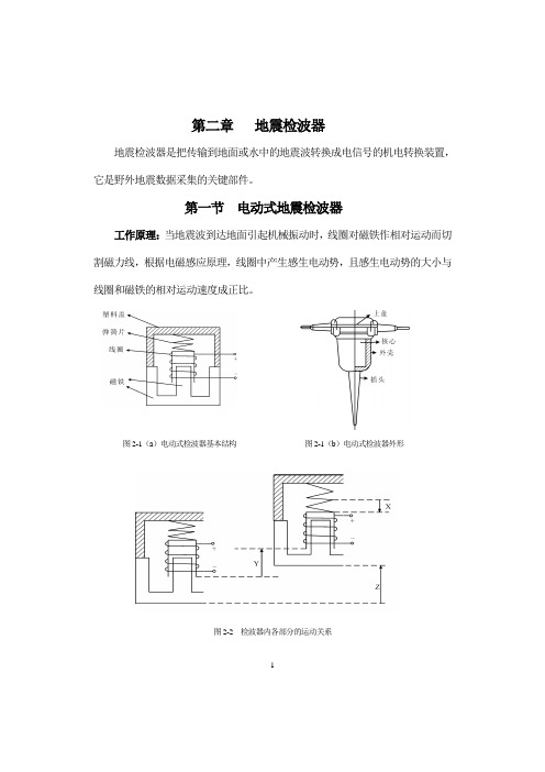
第二章地震检波器地震检波器是把传输到地面或水中的地震波转换成电信号的机电转换装置,它是野外地震数据采集的关键部件。
第一节电动式地震检波器工作原理:当地震波到达地面引起机械振动时,线圈对磁铁作相对运动而切割磁力线,根据电磁感应原理,线圈中产生感生电动势,且感生电动势的大小与线圈和磁铁的相对运动速度成正比。
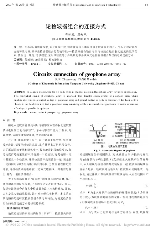
图2-1(a)电动式检波器基本结构图2-1(b)电动式检波器外形图2-2 检波器内各部分的运动关系图2-2 检波器内各部分的运动关系12一、运动方程的建立运动方程反应的是检波器线圈运动与地面运动的关系。
规定:z ——地面产生的向上位移y ——线圈框架(惯性体)的向上位移x ——线圈相对磁铁的向下位移(x <0),并且:y z x =+1.弹簧克服惯性体重力后的拉力K FK F kx =- (2-1)2. 线圈受到的电磁阻尼力根据法拉第电磁感应定律,线圈两端输出的电动势为dtdxs dt dx dx d n dt d ne ⋅=⋅==φφ dxd ns φ=称为机电转换系数,也叫空载灵敏度。
线圈中的感应电流为:c o e ei R R R==+式中c R 是线圈内阻,o R 是线圈负载电阻。
感应电流受到的电磁力L F :dtdx R s R e s i dx d n F L ⋅-=⋅-=⋅-=2φ (2-2) 3. 铝制线圈框架受到的电磁阻尼力当圆筒形铝制线圈框架在磁场中运动时,线圈框架内将产生涡电流。
涡电流产生涡旋磁场,此涡旋磁场与永久磁场相互作用的结果也是阻止线圈框架的运3动,这种电磁阻尼力与线圈框架相对磁铁的运动速度成正比:dtdxF T μ-= (2-3) 根据牛顿第二定律,将式(2-1)、(2-2)和(2-3)相加:2222222()k L T s dxF F F k x R dtd yd z d x M M dt dtdt μ++=-⋅-+⋅⎛⎫=⋅=⋅+ ⎪⎝⎭ 即 222221dtzd x M k dt dx R s M dt x d -=+⋅⎪⎪⎭⎫ ⎝⎛+⋅+μ (2-4) 一般式 2220222dtz d x dt dx h dt x d -=++ω (2-5)MRs h 2/2+=μ——衰减系数,M K /0=ω——自然频率 。
天津大学硕士学位论文三分量全光纤...

天津大学硕士学位论文三分量全光纤加速度地震检波器的研制姓名:***申请学位级别:硕士专业:光学工程指导教师:***20030101中文摘要“三分量全光纤加速度地震检波器的研制”是国家自然科学基会资助项目“三分量全光纤加速度地震检波技术的理论与实验研究”的子课题。
三分量全光纤加速度地震检波器是在本研究室研制的“单分量顺变柱体型全光纤加速度地震检波器”的基础上,研制成功的一种可以实现三维空间加速度三个分量(a。
,a。
,az)的并行,实时,高精度检测的新型加速度地震检波器。
该检波器的三个检测分量用6个顺变柱体共同支撑一个质量块,并采用三个迈克尔逊光纤干涉传感系统,构成三维简谐振子系统。
可广泛用于地震监测,工程振动测量,航空航天惯性导航以及石油天然气和会属矿藏的开采等领域,理论计算表明,灵敏度可达到2.89x10³rad/g,可探测到的最小加速度为10ng/、/Hz。
本文对三分量全光纤加速度地震检波器进行了深入的理论研究:从光纤传感的机理出发,利用牛顿定律、光纤应力应变效应阻及顺变柱体特性推导出了相干光相位差与外界加速度场之间的关系,建立了三维简谐振子系统的振动力学模型,并进行了三分量光纤传感系统的受力分析计算。
文中首先对检波器单个分量检测单元的工作原理、结构设计及关键部件顺变柱体的特性进行了简单介绍。
进而详细阐述了三分量检波器的系统结构设计,相位补偿技术及信号处理电路。
在上述理论研究的基础上,我们成功的设计出了新型的三维空心顺变柱体型双光路简谐振子系统,完成了三分量检波器样机的制备,在丹麦PMVibrationExciter4808震动台上对其进行了模拟实验测试,结果表明,检波器样机的输出信号与振动台信号一致,频响特性曲线与理论计算相符,加速度灵敏度为12mv/cm/s2。
关键字:三分量顺变柱体全光纤迈克尔逊干涉仪加速度地震检波器Abstract“Developementofthree—componentall·fiberaccelerationseismicgeophone”isthesub—pr两ectof“Thetheoreticalandexperimentresearchonthree-componentall—fiberaccelerationseismicgeophonetechnology”whichissuppoaedbyNaturalScienceFoundationofChina。
地震检波器的分类及应用

地震检波器的分类及应用
地震检波器是一种用于检测地震波的传感器,它可以将地震波转化为电信号,然后通过数据采集系统记录下来。
地震检波器的分类及应用如下:
- 按频率响应范围分类:
- 宽频带地震检波器:这种检波器的频率响应范围较宽,可以检测到不同频率的地震波,适用于地震监测和研究。
- 高频地震检波器:这种检波器的频率响应范围较高,可以检测到高频地震波,适用于浅层地震勘探。
- 按使用环境分类:
- 陆地地震检波器:这种检波器适用于陆地环境,可以检测到地震波在不同介质中的传播情况。
- 海洋地震检波器:这种检波器适用于海洋环境,可以检测到地震波在海洋中的传播情况。
- 按工作原理分类:
- 压电地震检波器:这种检波器利用压电材料的压电效应,将地震波转化为电信号。
- 电磁地震检波器:这种检波器利用电磁感应原理,将地震波转化为电信号。
地震检波器在地震监测、地震勘探、地球物理研究等领域有着广泛的应用。
在地震监测中,地震检波器可以检测到地震波的到达时间、强度、频率等信息,为地震预警和地震研究提供数据支持。
在地震勘探中,地震检波器可以检测到地下不同深度的地震波,为地质勘探提供数据支持。
在地球物理研究中,地震检波器可以检测到不同类型的地震波,为地球物理研究提供数据支持。
- 1、下载文档前请自行甄别文档内容的完整性,平台不提供额外的编辑、内容补充、找答案等附加服务。
- 2、"仅部分预览"的文档,不可在线预览部分如存在完整性等问题,可反馈申请退款(可完整预览的文档不适用该条件!)。
- 3、如文档侵犯您的权益,请联系客服反馈,我们会尽快为您处理(人工客服工作时间:9:00-18:30)。
Geophone element testingMalcolm B. Bertram and Eric V. GallantABSTRACTA new system incorporating a laser interferometer for measuring geophone element characteristics is being developed. The purpose is to determine absolute measurements of linearity, distortion and phase for elements of different frequency, manufacture and orientation. This apparatus will also be used to measure the coupling of the elements in the auto-orienting sensor now in the process of being patented.INTRODUCTIONWith the advance in resolution of seismic acquisition instrumentation in the last few years, there has been a demand for geophone improvement to complement the 24 bit systems. To meet this requirement, all the geophone manufacturers have brought out new products designed for 24 bit compatibility. In some cases, this has been accomplished by tighter tolerance in the manufacturing process, and in other cases there has been a complete redesign of the element - for example using rare earth magnets. The purpose of this paper is to present a new method of testing these geophones to determine whether they do in fact meet the expected specifications.TESTING METHODSCurrently geophone manufacturers use a current pulse applied to the coil to test elements for frequency and freedom of motion. This is followed by the application of a very low distortion sinusoidal current which drives the element over a known displacement. The voltage across the coil is sampled and used to calculate the distortion parameters. With careful design and application this method can indeed provide good quality information on the element under test. The use of a shaker table for element testing has been relegated to coarse measurements only, and as a quality control system for strings of geophones. Because of the extremely high resolution required to test "24 bit" geophones it is not possible to drive a mechanical shaker table with sufficient linearity to produce the necessary accuracy.The method of testing geophones presented here does in fact use a shaker table, but the drive applied to the table does not require particularly high fidelity. Instead the actual movement of the element case is tracked by a laser interferometer which provides a positional accuracy of 84 nanometers. This output is compared with the electrical output from the element under test, which will be captured using a 24 bit Analog to Digital converter as is common in the seismic industry. For the first pass however, the signal will be acquired using a digital oscilloscope. The actual distortion, linearity and phase can then be measured for a range of different input displacements and frequencies. The table drive can also superimpose a high frequency low amplitude signal on a low frequency high amplitude signal to test the coil response at different physical displacements, simulating the signal-under-groundroll problem.Measurements will be made on a representative sample of elements in a new condition, then after "aging" to represent field use. Testing will include consistency between elements, and changes in measured parameters after several stages of aging.Fig 1. Diagram of the testing equipment setupSYSTEM DESIGNThe main element of the shaker table is a 15 inch speaker which will provide drive down to frequencies well below 1 Hz. This is driven by a 50 watt power amplifier fed from a signal source. The signal source is either a signal generator or a PC card which can provide a synthetic waveform of any desired shape. The speaker is mounted in a solid box with a thin diaphragm suspended about 1 cm above the outer frame of the speaker. The space between the speaker cone and the diaphragm is sealed to provide pneumatic coupling to the diaphragm, while removing the weight of the parts being tested from the speaker cone itself. (Figure 1)The laser interferometer is mounted above the centre of the diaphragm by means of a frame which decouples the interferometer from ambient vibration. This means that the interferometer output will include this ambient motion, which will produce some output from the element under test in combination with the speaker drive.Without this decoupling the signal generated by the element as a result of the ambient noise would effect the measurement of distortion and linearity.To reduce this ambient noise as much as possible, the whole system is mounted on a solid inertial plate decoupled from the supporting table.Las er interfe rometerC o rner prismG eop hone e lem entD iaphragmS peakerMetal sla bD eco upling materi alS ta ndC ounte r A / DLASER INTERFEROMETERThe laser interferometer is a commercial product used for very high accuracy positioning and measuring purposes. A 672 nanometer (red) laser beam is passed through a beam splitter, then one of the outputs is transmitted through a transparent window to an external corner prism which returns the beam to the interferometer via a second window. This input is combined with the second output from the beam splitter to produce a detectable fringe pattern. There are two detectors operating in quadrature to provide an easily decoded signal for input to an up / down counter. Using a simple decoding scheme, there are 4 changes of state for each wavelength change of external beam path length, corresponding to a half wavelength movement by the prism. Thus there is a counter pulse every 84 nanometers.For measuring geophone element characteristics, the corner prism is attached directly to the case of the element, ensuring accurate tracking.The laser interferometer used for this particular apparatus is a LARS/200 manufactured by Gradient Lens Corporation.AUTO-ORIENTING GEOPHONEThe parameter of most concern for the auto-orienting geophone is the coupling between the outer case and the inner sphere. This is measured by attaching a second element, identical to the internal one being tested, to the outside of the case, so that the element output is a direct measure of the outer case motion. This output is then compared to the output from the internal element to provide a measure of coupling. The laser interferometer will also be utilised to provide constraints on the experiment such as maximum amplitude of motion.The apparatus is designed for both vertical and horizontal operation, allowing both element orientations to be tested. As well, tilting at different angles will supply information on allowable limits in geophone planting.OTHER APPLICATIONSBecause of its small size and easy portability the laser interferometer can be used in the field to measure the actual ground motion on a seismic spread at various offsets. By capturing this signal, the experimental apparatus can then be used to re-create the motion experienced by a geophone in the field, thus providing a unique way of comparing different elements under field conditions.CONCLUSIONThe test equipment is still being assembled, and many modifications are expected before the true testing to high accuracy can be started. The first pass will indicate whether this is indeed a viable method of testing high performance geophones.ACKNOWLEDGEMENTSPeter Maxwell of the SENSOR division of Input/Output Inc. has provided valuable information on geophone testing methods currently used.Mark Products, Geospace and SENSOR will all provide elements for testing on this system.The CREWES Project and the Department of Geology and Geophysics at the University of Calgary have provided support and instrumentation for the testing equipment.。