ACSC02-41CGKWA-F01, 规格书,Datasheet 资料
样本 丹佛斯 电磁阀

波兰(Polski Rejestr Ststkow) 俄罗斯(MRS) 也可提供通过 UL 认证产品。
DKRCC.PD.BB0.B3.41 / 520H7191
参数表 技术数据
2
电磁阀,型号 EVR 2 − 40 NC/NO
制冷剂
R22/R407C、 R404A/R507 、R410A、R134a、R407A、 R23。如需使用其他 制冷剂,请洽询 Danfoss。
R404A/ R507 1.20 2.00 6.00 14.30 19.60 37.70 45.20 75.30 120.00 188.00
பைடு நூலகம்
液体和吸气名义制冷量的工况条件为:
蒸发温度 te = -10 °C 阀门前液体温度 tl = 25 °C 经过电磁阀压力降 ∆p = 0.15 bar
热气名义制冷量的工况条件为:
—
a.c./ d.c. 1/2 12 032F8095 032F1217 032F1218
—
a.c./ d.c. 5/8 16 032F8098 032F1214 032F1214
—
a.c./ d.c. 5/8 16 032F8101 032F1228 032F1228
—
a.c./ d.c. 5/8
—
d.c.
7/8
22
—
—
—
032F1274
a.c.
1 3/8 35
—
032F3267 032F3267
—
a.c./ d.c. 1 1/8
—
—
—
032F2200
a.c./ d.c. — 28
—
—
—
032F2205
ACDC56-41CGKWA-F01中文资料

SPEC NO: DSAG0253 APPROVED: WYNEC
REV NO: V.5 CHECKED: Joe Lee
DATE: JUN/14/2007 DRAWN: Y.L.LI
PAGE: 1 OF 5 Eelection Guide
PAGE: 5 OF 5 ERP: 1352000321
Note: 1. 1/10 Duty Cycle, 0.1ms Pulse Width.
Green 75 30 150 5 -40°C To +85°C
Units mW mA mA V
SPEC NO: DSAG0253 APPROVED: WYNEC
REV NO: V.5 CHECKED: Joe Lee
Notes: 1.Wavelength: +/-1nm. 2. Forward Voltage: +/-0.1V.
Absolute Maximum Ratings at TA=25°C
Parameter Power dissipation DC Forward Current Peak Forward Current [1] Reverse Voltage Operating / Storage Temperature
Part No. Dice Lens Type Iv (ucd) [1] @ 10mA Min. ACDC56-41CGKWA-F01 Green (InGaAlP) WHITE DIFFUSED 8000 Typ. 35500 Common Cathode, Rt. Hand Decimal Description
元器件交易网
SURFACE MOUNT DISPLAY
Part Number: ACDC56-41CGKWA-F01 Green
CSA502-P044T01S 电流传感器使用说明书
CSA502-P044T01S 电流传感器使用说明书V1.4本手册为湖南银河电气有限公司产品CSA502-P044T01S电流传感器用户手册,本手册为用户提供安装调试、操作使用及日常维护的有关注意事项,在安装、使用前请仔细阅读。
本手册随产品一起提供,请妥善保管、以备查阅和维护使用。
声明我们非常认真的整理此手册,但我们对本手册的内容不保证完全正确。
因为我们的产品一直在持续的改良及更新,故我方保留随时修改本手册的内容而不另行通知的权利。
同时我们对不正确使用本手册所包含内容而导致的直接、间接、有意、无意的损坏及隐患概不负责。
安全操作知识◆产品使用前,请您务必仔细阅读用户手册。
◆需对产品进行搬动时,请您务必先断电并将与之相连的所有连接线缆等拔掉。
◆如果发现机壳、稳固件、电源线、连接线缆,或相连的设备有任何损坏,请您立即将装置与电源断开。
◆如果对设备的安全运行存在疑虑,应立即关闭设备和相应附件,并在最快时间内与本公司技术支持部门取得联系,沟通解决。
!安全警示 电流传感器不允许开路使用,即母线有电流或传感器已上电的状态下,都不允许断开输出端;仅母线无电流且传感器未上电的状态下,才可以断开传感器的电流输出端或主机与探头的连接,否则有感应高压,发生电击的危险!1. 产品概述CSA502-P044T01S 一种能在原边、副边完全隔离条件下测量直流、交流、脉冲以及各种不规则波形的电流传感器,它主要用于要求准确度高的计量检定和计量校准领域,以及要求高灵敏度、高稳定性和高可靠性的电能质量分析、功率分析仪、医疗、航空航天、导弹、舰艇等领域。
2. 技术特点● 极高的准确度 ● 极好的线性度 ● 极高的稳定性 ● 极高的灵敏度 ● 极高的分辨率 ● 极低的温度漂移 ● 极低的失调电流● 极低的插入损耗 ● 抗干扰能力强 ● 响应速度快 ● 极低的噪声 ● 极小的角差 ● 宽频带 ● 模拟量输出 3. 应用场合● 计量检定与校准 ● 实验室电流测量● 仪器仪表(如功率分析仪) ● 医疗设备(如核磁共振MRI ) ● 电池组检测 ● 电力控制 ● 电源 ● 舰船 ● 新能源 ● 轨道交通 ● 航空航天 ● 工业测量4. 电气性能项目符号测试条件数值单位最小标称最大原边额定电流 I PN -- -- ±5000 -- Adc 测量范围 I PM 1分钟/小时 -- -- ±6000 Adc 工作电压 V c 全范围 90 220 260 Vac 电源消耗 I PM 范围内 -- 150 -- W 电流变比 K N 输入:输出 5000:1 --额定输出电流 I SN 原边额定电流-- ±1 -- A测量电阻R M0 -- 1 Ω5. 精度-动态参数项目符号测试条件数值单位最小标称最大精度 X e 输入直流,25±10℃ -- -- 10 ppm 比差误差 X Ge 输入交流50Hz/60Hz ,25±10℃-- -- 100 ppm 角度误差 X Pe -- -- 0.01 crad线性度εL-- -- -- 2 ppm温度漂移系数 TCI OUT -- -- -- 0.1 ppm/K时间漂移系数 TT -- -- -- 0.2 ppm/month供电抗干扰 TV -- -- -- 1 ppm/V 零点失调电流 I o 25±10℃ -- -- 2 ppm 零点失调电流 I oT 全工作温度范围内-- -- ±10 ppm纹波电流 I n DC-10Hz -- -- 0.5 ppm 动态响应时间 t r di/dt=100A/us 上升至90% I PN-- -- 1us电流跟随速度 di/dt -- 200 -- -- A/us 频带宽度(- 3 dB)F-- 0 -- 20 kHz6. 一般特性项目符号测试条件数值单位最小标称最大工作温度范围 T A -- -10 -- +70 ℃ 存储温度范围T S-- -25 -- +85 ℃电流探头检测信号 -- 正常工作时,红色探头检测灯常亮,DB9插座第4脚和第9脚处于无信号输出的开路状态。
伟肯变频器用户手册
伟肯变频器用户手册安装和运行前,请务必遵照如下的起动和运行快速指南操作,并依次完成其中11个操作步骤。
如有任何问题,请与当地经销商联系。
快速指南1. 检查产品是否与定单相符,见第3章。
2. 进行任何调试前,请仔细阅读第1章中的安全规程。
3. 进行机械安装前,请根据第5章的说明检查外部环境条件和变频器周边的最小间距。
4. 按第6章的说明检查电机电缆、主电源电缆、主电源熔断器的规格和电缆的连接情况。
5. 根据第5章中的安装说明进行安装。
6. 根据§6.1.1中的说明检查控制电缆规格及接地系统。
7. 根据第7章中的说明使用控制面板。
8. 所有的参数都有工厂设定的缺省值。
为了确保正确运行,请检查下列电机铭牌数据和参数组P2.1中相应的参数设置。
见§8.3.2。
• 电机额定电压P2.1.6• 电机额定频率P2.1.7• 电机额定转速P2.1.8• 电机额定电流P2.1.9• 电机功率因数P2.1.10所有的参数说明见多目标控制应用手册。
9. 阅读第8章,按照调试步骤进行操作。
10. 至此,可以开始使用Vacon NXL变频器了。
11. 在本手册的结尾,您会看到有关默认I/O,控制面板菜单,监控值,故障代码和基本参数的快速帮助。
违反上述操作步骤所造成的任何损失,Vacon Plc概不负责。
目录VACON NXL用户手册目录1 安全指导2 EU认证3 收货4 技术数据5 安装6 电缆和接线7 控制面板8 调试9 故障跟踪10 选件卡OPT-AA的描述11 选件卡OPT-AI的描述VACON NXL多目标控制应用手册vacon • 3Vacon China电话: +86-10-51280006 传真: +86-10-65813733 24小时支持热线: +86-137******** Email :***************.cn关于VACON NXL 用户手册和多目标控制应用手册恭喜您选择了Vacon NXL 变频器所提供的平滑控制!用户手册将为您提供有关Vacon NXL 变频器的安装,调试和操作的必要信息。
嘉科米尼阀门资料

PART NUMBER
R401X132* R401X133* R401X034 R401X035
SIZE
3/8” 1/2” 3/4” 1”
10 100 10 100
5 50 2 20
R402TG
Straight valve with thermostatic option, chrome plated, with iron pipe connection, self-sealing tail piece, with cover to protect body before assembling.
锁闭直阀 螺丝口 带自密封式尾管 镀铬
PART NUMBER
R15X032* R15X033* R15X034 R15X035 R15X036
SIZE
3/8”x3/8” 1/2”x1/2” 3/4”x3/4”
1”x1” 1”1/4x1”1/4
10 100 10 100
5 50 2 20 2 20
R29TG
PART NUMBER
R29X032* R29X033* R2ቤተ መጻሕፍቲ ባይዱX034* R29X035 R29X036
SIZE
3/8”x16 1/2”x16 1/2”x18 3/4”x18 3/4”x22
* Self-sealing tail pieces - 自密封式尾管
capitolo1_uk-cn.indd 3
SIZE
3/8”x3/8” 1/2”x1/2” 3/4”x3/4”
1”x1” 1”1/4x1”1/4
10 100 10 100
5 50 2 20 2 20
Oxymax W COS41 溶解氧传感器说明书
Brief Operating InstructionsOxymax W COS41Dissolved oxygen sensorThese instructions are Brief Operating Instructions.For detailed information, please read the Operating Instructions and the special instructions on the supplied CD-ROM.The complete device documentation comprises:•these Brief Operating Instructions•the Operating Instructions on the supplied CD-ROM•if necessary, certificates and calibration protocols (acc. to the version).KA284C/07/en/06.0571002048Table of contents Oxymax W COS41 Table of contents1 Safety instructions. . . . . . . . . . . . . . . . . . . . . . . . . . . . . . . . . . . . . . . . . . . . . . . . . 21.1 Designated use . . . . . . . . . . . . . . . . . . . . . . . . . . . . . . . . . . . . . . . . . . . . . . . . . . . . . . . . . . . . . . . . . . . . . . . . . . 21.2 Installation, commissioning and operation . . . . . . . . . . . . . . . . . . . . . . . . . . . . . . . . . . . . . . . . . . . . . . . . . . . . . . 21.3 Operational safety . . . . . . . . . . . . . . . . . . . . . . . . . . . . . . . . . . . . . . . . . . . . . . . . . . . . . . . . . . . . . . . . . . . . . . . . 32 Installation. . . . . . . . . . . . . . . . . . . . . . . . . . . . . . . . . . . . . . . . . . . . . . . . . . . . . . 32.1 Installation conditions . . . . . . . . . . . . . . . . . . . . . . . . . . . . . . . . . . . . . . . . . . . . . . . . . . . . . . . . . . . . . . . . . . . . . 32.2 Installation instructions . . . . . . . . . . . . . . . . . . . . . . . . . . . . . . . . . . . . . . . . . . . . . . . . . . . . . . . . . . . . . . . . . . . . 42.3 Installation examples . . . . . . . . . . . . . . . . . . . . . . . . . . . . . . . . . . . . . . . . . . . . . . . . . . . . . . . . . . . . . . . . . . . . . 52.4 Post installation check . . . . . . . . . . . . . . . . . . . . . . . . . . . . . . . . . . . . . . . . . . . . . . . . . . . . . . . . . . . . . . . . . . . . 83 Wiring . . . . . . . . . . . . . . . . . . . . . . . . . . . . . . . . . . . . . . . . . . . . . . . . . . . . . . . . . 93.1 Direct connection to the transmitter . . . . . . . . . . . . . . . . . . . . . . . . . . . . . . . . . . . . . . . . . . . . . . . . . . . . . . . . . . 93.2 Connection via junction box . . . . . . . . . . . . . . . . . . . . . . . . . . . . . . . . . . . . . . . . . . . . . . . . . . . . . . . . . . . . . . . 104 Commissioning. . . . . . . . . . . . . . . . . . . . . . . . . . . . . . . . . . . . . . . . . . . . . . . . . . 114.1 Function check . . . . . . . . . . . . . . . . . . . . . . . . . . . . . . . . . . . . . . . . . . . . . . . . . . . . . . . . . . . . . . . . . . . . . . . . . 114.2 Polarization . . . . . . . . . . . . . . . . . . . . . . . . . . . . . . . . . . . . . . . . . . . . . . . . . . . . . . . . . . . . . . . . . . . . . . . . . . . 114.3 Calibration . . . . . . . . . . . . . . . . . . . . . . . . . . . . . . . . . . . . . . . . . . . . . . . . . . . . . . . . . . . . . . . . . . . . . . . . . . . . 121Safety instructions1.1Designated useThe oxygen sensor is suitable for continuous measurement of dissolved oxygen in water.Typical applications are:•Measuring, monitoring and regulating the oxygen content in activated sludge basins.•Monitoring the oxygen content in the sewage treatment plant outlet.•Monitoring, measuring and regulating the oxygen content in public waters and fish farming water.•Monitoring of oxygen enrichment in drinking water.Any other use than the one described here compromises the safety of persons and the entire measuring system and is, therefore, not permitted.The manufacturer is not liable for damage caused by improper or non-designated use.1.2Installation, commissioning and operation•The device/measuring system may only be installed, connected, operated and maintained by trained technical personnel (e.g. certified electrician). The technical personnel must strictlyadhere to the Operating Instructions, prevailing standards, legal regulations and certificates(depending on application).•If the Brief Operating Instructions do not provide sufficient information, you must read theOperating Instructions. There, you can find detailed information on the device.2Endress+HauserOxymax W COS41InstallationEndress+Hauser 3•The operator may only perform modifications and repairs of the device/measuring system that are explicitly permitted in the Operating Instructions.•Do not operate damaged products and secure them against unintentional commissioning. Mark the damaged product as being defective.•If faults can not be rectified, the products must be taken out of service and secured against unintentional commissioning.1.3Operational safetyThe sensor has been designed and tested according to the state of the art and left the factory in perfect functioning order.Relevant regulations and European standards have been met.As the user, you are responsible for complying with the following safety conditions: •Installation instructions•Local prevailing standards and regulations."Caution!Pay attention to the technical data on the name plate!2Installation2.1Installation conditions2.1.1OrientationOther angles are not permitted. Do not install the sensor overhead.Fig. 1: Angle of installation ARecommended angle of installation: 0 ... 180 °Installation Oxymax W COS414Endress+Hauser2.1.2Mounting location•Select the installation location so that there is easy access for later calibration.•Make sure that upright posts and assemblies are secured safely and vibration-free.•For immersed operation in an activated sludge basin, select an installation location which produces a typical oxygen concentration.2.2Installation instructions2.2.1Installing a measuring point!Note!For immersed operation, install the individual modules away from the basin on a solid base. Only carry out the final installation at the intended installation location.For a complete installation of a measuring point, proceed as follows:1.Install a retractable or a flow assembly (if used) into the process.2.Connect the water supply to the rinse connections (if you use an assembly with cleaning function).3.Install and connect the oxygen sensor.4.Install an immersion or an suspension assembly (if used) into the process."Caution!•For immersed operation, the sensor must be installed in an immersion assembly (e.g. CYA611). Do not install the sensor suspended from the cable.•Screw the sensor into the assembly so that the cable is not twisted.•Avoid exerting excessive tensile force on the cable (e.g. from jerky pulling).•Select the installation location so that there is easy access for later calibration.#Warning!When using metallic assemblies and installation equipment, comply with national grounding regulations.Oxymax W COS41InstallationEndress+Hauser 52.3Installation examples2.3.1Immersion operationUniversal assembly holder and chain assemblyFig. 2: CYH101 with immersible pendulum assembly 1Weather protection cover2Upright post, square pipe SS AISI 3043Transverse pipe SS AISI 3044Star handle5Second fixing possibility for transverse pipe 6Immersion assembly CYA 611Fig. 3: Immersion assembly CYA 6111Protection cap2Worm drive hose clip3Pipe clips (detailed drawing in right half)4PVC pipe5Threaded couplingInstallation Oxymax W COS41 Universal assembly holder and fixed immersion assemblyFig. 4: Universal suspension assembly holder CYH101 with immersion assembly CYY1051Star handle2Pipe holder3Fixing bracket4Immersion assembly (= immersion tube)6Endress+HauserOxymax W COS41InstallationEndress+Hauser 7Basin rim mounting with immersion tubeFloating bodyFig. 5: Horizontal basin rim mounting 1Protection cover for cable entry 2Assembly holder3Immersion assembly SS 1.4301 (AISI 304)Fig. 6: Vertical basin rim mounting 4Basin rim mounting 5Star handleFig. 7: Floating body1234567Cable route with strain relief and rain protection Mounting ring for ropes and chains with locking screwLugs Ø15, 3 x 120 ° for anchoring Saltwater-resistant plastic floatPipe 40x1, stainless steel 1.4571 (AISI 316Ti)Shock absorber and weight Oxygen sensorInstallation Oxymax W COS418Endress+Hauser2.3.2Flow assembly2.4Post installation check•Check the membrane for leak tightness und replace it if necessary.•Sensor and cable undamaged?•Compliance with permissible sensor installation position?•Is the sensor installed in an assembly and is not suspended from the cable?•Avoid moisture by rain by fitting the protective cap to the immersion assembly?Fig. 8: Flow assembly COA250-B 1Screw-in part for sensor 2Screw ring 3Meter body4Connection thread G¾5Dummy plug (connection for spray head COR3)Fig. 9: Bypass installation1Main line 2Medium return 3Oxygen sensor4, 7Manually actuated or solenoid valves 5Flow assembly COA250-B 690 ° pipe bracket 8Medium removalOxymax W COS41WiringEndress+Hauser 93Wiring#Warning!•The electrical connection must only be carried out by a certified electrician.•Technical personnel must have read and understood the instructions in this manual and must adhere to them.•Ensure that there is no voltage at the power cable before beginning the connection work.3.1Direct connection to the transmitterThe sensor is connected using a special measuring cable (→å 10). The wiring diagram is contained in the Operating Instructions of the COM223/253-DX/DS transmitter.!Note!The interior white and yellow pilot wires have no function.Fig. 10: Special measuring cable CYK 71Terminal S 12909111AssignmentOuter shieldActive inner shield (NTC)Cathode AnodeNTC temperature sensorWiring Oxymax W COS413.2Connection via junction boxTo lengthen the sensor connection beyond the length of the fixed cable, you require a junction box VBM. The connection is lengthened to the transmitter using the special measuring cable CYK71.Fig. 11: Connection via junction box VBM1Sensor2Junction box3Extension cable4Transmitter10Endress+HauserOxymax W COS41CommissioningEndress+Hauser 114Commissioning 4.1Function checkBefore first commissioning, check if:•the sensor is correctly installed•the electrical connection is correct.If using an assembly with automatic cleaning, check the correct water connection at theassembly rinse connection.#Warning!Danger of medium leaking offBefore applying compressed air to an assembly with cleaning facility, make sure the connections are correctly fitted. Otherwise, the assembly may not be insert into the process.4.2PolarizationThe sensor was tested in the factory for perfect functionality and is supplied ready for operation.To prepare for calibration, proceed as follows:1.Remove the sensor protective cap.2.Place the externally dry sensor in atmospheric air. The air should be saturated with watervapour. Therefore, install the sensor as close to the water surface as possible. Whencalibrating the sensor membrane, make sure the membrane remains dry. Therefore, avoidany direct contact with the water surface.3.Connect the sensor to the transmitter and switch on the transmitter.4.Switch-on the transmitter.If you connect the sensor to the transmitter Liquisys M COM223/253, polarisation isautomatically performed after switching on the transmitter.5.The polarisation time takes about 1 hour.!Note! Polarisation starts high, then drops gradually. You will recognise the end of polarisation when the display stabilises and remains practically constant."Caution!•When you remove the sensor from the medium, protect the sensor from strong sunlight.•Make sure you comply with the instructions for commissioning and calibration in theOperating Instructions of the transmitter.4.3CalibrationCalibrate the sensor (calibration type "Air") immediately after it’s polarization.1.Remove the sensor from the medium.2.Clean the outside of the sensor with a damp cloth. Then dry the sensor membrane e.g.by using a tissue.3.If the sensor is removed from a closed pressure system with a process pressure greaterthan atmospheric pressure:–Open the membrane cap to equilibrate the pressure and clean the cap if necessary.–Replace the electrolyte filling and close the membrane cap again.–Wait for the polarisation time to end.4.Then wait while the sensor adjusts to the temperature of the ambient air. This takesabout 20 minutes. Check that the sensor is not in direct sunlight during this time.5.If the measured value display on the transmitter is stable, carry out the calibration inaccordance with the Operating Instructions of the transmitter.6.Place the sensor in the medium again.!Note!Make sure you comply with the instructions for calibration in the Operating Instructions of the transmitter./worldwideKA284C/07/en/06.05Printed in Germany / FM+SGML 6.0 /DT71002048。
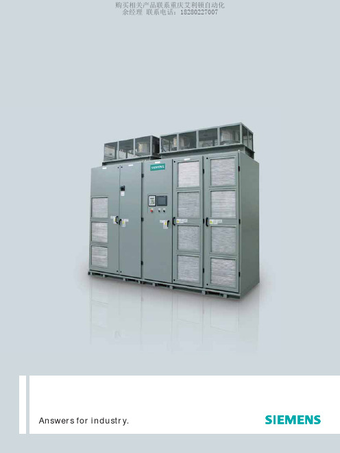
西门子罗宾康高压变频器
C7
B8
C8
10-11kVAC INDUCTION MOTOR
10-11kVAC 变频器拓扑
设计差异
罗宾康完美无谐波变频器已获专利的集成 设计可确保电源控制行业中无与伦比的可 靠性、高效性和多功能性。罗宾康完美无 谐波的设计能够耐受可能损坏传统驱动系 统的故障。
传统的变频器通常有五个单独的组件,如 谐波滤波器、功率因数校正、变压器、功 率变频器和电机滤波器。罗宾康完美无谐 波的拓扑只需要隔离变压器和功率变频器 这两个主要组件。集成系统可以实现快速、
购买相关产品联系重庆艾利顿自动化 余经理 联系电话:18280227007
满足最高要求的变频器选择
—— 可靠、精确、耐用
罗宾康完美无谐波
Answers for industry.
购买相关产品联系重庆艾利顿自动化 余经理 联系电话:18280227007
罗宾康完美无谐波 完美无谐波系列的性能和价值
能源机构资料表明,工业电机每年耗费数万亿度的电能,超过全球全部用电的50%。优化 的系统,例如合理的选型,效率更高的驱动机构以及变频调速设备等都将有助于降低能量 消耗。这意味着选择合适的变频器可以实现对电机、风扇、泵和其他设备更为精确、有效 的控制,从而有助于降低运行成本。
光明的前途建立在坚实的基础之上
罗宾康完美无谐波变频器于1994年问世以 来,对电力转换进行了一次重大变革,在 可靠性和创新方面不断树立工业标准。由于 功率开关器件技术促进和提高了输出电压能 力,西门子对各代罗宾康完美无谐波的改进 主要表现在以下三个方面:提高可靠性和可 用性、提高效率和减小变频器尺寸。
测量的功率因数
ROBICON Perfect Harmony
12 脉冲谐波波形 • 电压总失真为5.9% • 电流总失真为8.8%
Modicon M241 产品数据手册说明书

i s c l a im e r : T h i s d o c u m e n t a t i o n i s n o t i n t e n d e d a s a s u b s t i t u t e f o r a n d i s n o t t o b e u s e d f o r d e t e r m i n i n g s u i t a b i l i t y o r r e l i a b i l i t y o f t h e s e p r o d u c t s f o r s p e c i f i c u s e r a p p l i c a t i o n sProduct datasheetCharacteristicsTM241CE40Tcontroller M241 40 IO transistor PNP EthernetMainRange of productModicon M241Product or component type Logic controller [Us] rated supply voltage 24 V DCDiscrete input number 24 discrete input including 8 fast input conforming to IEC 61131-2 Type 1Discrete output type TransistorDiscrete output number 16 transistor including 4 fast output Discrete output voltage 24 V DC for transistor outputDiscrete output current0.1 A with Q0...Q3 terminal(s) for fast output (PTO mode)0.5 A with Q0...Q15 terminal(s) for transistor outputComplementaryDiscrete I/O number40Number of I/O expansion module 7 (local I/O architecture)14 (remote I/O architecture)Supply voltage limits 20.4...28.8 V Inrush current<= 50 APower consumption in W 32.6...40.4 W with max number of I/O expansion module Discrete input logic Sink or source Discrete input voltage 24 V Discrete input voltage type DCVoltage state1 guaranteed >= 15 V for input Current state 1 guaranteed >= 2.5 mA for input >= 5 mA for fast input Voltage state 0 guaranteed <= 5 V for input Current state 0 guaranteed <= 1 mA for input<= 1.5 mA for fast input Discrete input current 7 mA for input10.7 mA for fast input Input impedance4.7 kOhm for input2.81 kOhm for fast inputResponse time<= 2 µs turn-on operation with I0...I7 terminal(s) for fast input<= 2 µs turn-off operation with I0...I7 terminal(s) for fast input<= 2 µs turn-on operation with Q0...Q3 terminal(s) for fast output<= 2 µs turn-off operation with Q0...Q3 terminal(s) for fast output50 µs turn-on operation with I0...I15 terminal(s) for input50 µs turn-off operation with I0...I15 terminal(s) for input<= 34 µs turn-on operation with Q0...Q15 terminal(s) for output<= 250 µs turn-off operation with Q0...Q15 terminal(s) for outputConfigurable filtering time 1 µs for fast input12 ms for fast input0 ms for input1 ms for input4 ms for input12 ms for inputDiscrete output logic Positive logic (source)Output voltage limits30 V DCCurrent per output common 2 AOutput frequency<= 20 kHz for fast output (PWM mode)<= 100 kHz for fast output (PLS mode)<= 1 kHz for outputAccuracy+/- 0.1 % at 20...100 Hz for fast output+/- 1 % at 100 Hz...1 kHz for fast outputLeakage current<= 5 µA for outputVoltage drop<= 1 VTungsten load<= 2.4 WProtection type Short-circuit and overload protection with automatic resetReverse polarity protection for fast outputShort-circuit protectionReset time10 ms automatic reset output12 s automatic reset fast outputMemory capacity8 MB for program64 MB for system memory RAMData backed up128 MB built-in flash memory for backup of user programsData storage equipment<= 32 GB SD card optionalBattery type BR2032 lithium non-rechargeable, battery life: 4 yrBackup time 2 years at 25 °CExecution time for 1 KInstruction0.3 ms for event and periodic task0.7 ms for other instructionApplication structure8 external event tasks4 cyclic master tasks3 cyclic master tasks + 1 freewheeling task8 event tasksRealtime clock WithClock drift<= 60 s/month at 25 °CPositioning functions PWM/PTO function 4 channel(s) (positioning frequency: 100 kHz)Counting input number 4 fast input (HSC mode)Control signal type A/B signal at 100 kHz for fast input (HSC mode)Pulse/Direction signal at 200 kHz for fast input (HSC mode)Single phase signal at 200 kHz for fast input (HSC mode)Integrated connection type USB port with connector mini B USB 2.0Ethernet with connector RJ45Non isolated serial link "serial 1" with connector RJ45 and interface RS232/RS485Non isolated serial link "serial 2" with connector removable screw terminal block and interface RS485 Supply Serial link supply "serial 1" at 5 V, 200 mATransmission rate 1.2...115.2 kbit/s (115.2 kbit/s by default) for bus length of 15 m - communication protocol: RS4851.2...115.2 kbit/s (115.2 kbit/s by default) for bus length of 3 m - communication protocol: RS232480 Mbit/s for bus length of 3 m - communication protocol: USB10/100 Mbit/s - communication protocol: EthernetCommunication port protocol Modbus non isolated serial link with master/slave methodPort Ethernet 1 - 10BASE-T/100BASE-TX port with copper cable supportCommunication service FDRDownloadingIEC VAR ACCESSMonitoringNGVLProgrammingUpdating firmwareSMS notificationsDHCP server (via TM4 Ethernet switch network module)DHCP client (embedded Ethernet port)SNMP client/serverFTP client/serverSQL clientSend email from the controller based on TCP/UDP libraryModbus TCP client I/O scannerEthernet/IP originator I/O scanner (embedded Ethernet port)Ethernet/IP target, Modbus TCP server and Modbus TCP slaveLocal signalling 1 LED green for SD card access (SD)1 LED red for BAT1 LED green for SL11 LED green for SL21 LED per channel green for I/O state1 LED red for I/O error (I/O)1 LED red for bus fault on TM4 (TM4)1 LED green for Ethernet port activity1 LED red for module error (ERR)1 LED green for PWR1 LED green for RUNElectrical connection Removable screw terminal block for inputs and outputs (pitch 5.08 mm)Removable screw terminal block for connecting the 24 V DC power supply (pitch 5.08 mm) Cable length<= 50 m unshielded cable for input<= 10 m shielded cable for fast input<= 3 m shielded cable for fast output<= 50 m unshielded cable for outputInsulation500 V AC between fast input and internal logicNon-insulated between inputs500 V AC between output and internal logic500 V AC between fast output and internal logicNon-insulated between outputs500 V AC between input and internal logic500 V AC between output groups500 V AC between supply and internal logicNon-insulated between supply and groundMarking CESurge withstand 1 kV for power lines (DC) in common mode conforming to EN/IEC 61000-4-51 kV for shielded cable in common mode conforming to EN/IEC 61000-4-50.5 kV for power lines (DC) in differential mode conforming to EN/IEC 61000-4-51 kV for relay output in differential mode conforming to EN/IEC 61000-4-51 kV for input in common mode conforming to EN/IEC 61000-4-51 kV for transistor output in common mode conforming to EN/IEC 61000-4-5Web services Web serverMaximum number of connections8 connection(s) for Modbus server8 connection(s) for SoMachine protocol10 connection(s) for web server4 connection(s) for FTP server16 connection(s) for Ethernet/IP target8 connection(s) for Modbus clientNumber of slave16 Ethernet/IP64 Modbus TCPCycle time10 ms 16 Ethernet/IP64 ms 64 Modbus TCPMounting support Top hat type TH35-15 rail conforming to IEC 60715Top hat type TH35-7.5 rail conforming to IEC 60715Plate or panel with fixing kitHeight90 mmDepth95 mmWidth190 mmProduct weight0.62 kgEnvironmentStandards CSA C22.2 No 142ANSI/ISA 12-12-01UL 1604CSA C22.2 No 213EN/IEC 61131-2 : 2007Marine specification (LR, ABS, DNV, GL)UL 508Product certificationsCSA cULus RCMIACS E10Resistance to electrostatic discharge 4 kV on contact conforming to EN/IEC 61000-4-28 kV in air conforming to EN/IEC 61000-4-2Resistance to electromagnetic fields10 V/m (80 MHz...1 GHz) conforming to EN/IEC 61000-4-33 V/m (1.4 GHz...2 GHz) conforming to EN/IEC 61000-4-31 V/m (2 GHz...3 GHz) conforming to EN/IEC 61000-4-3Resistance to fast transients2 kV for power lines conforming to EN/IEC 61000-4-41 kV for Ethernet line conforming to EN/IEC 61000-4-41 kV for serial link conforming to EN/IEC 61000-4-41 kV for input conforming to EN/IEC 61000-4-41 kV for transistor output conforming to EN/IEC 61000-4-4Resistance to conducted disturbances,induced by radio frequency fields10 V (0.15...80 MHz) conforming to EN/IEC 61000-4-63 V (0.1...80 MHz) conforming to Marine specification (LR, ABS, DNV, GL)10 V (spot frequency (2, 3, 4, 6.2, 8.2, 12.6, 16.5, 18.8, 22, 25 MHz)) conforming to Marine specification (LR, ABS, DNV, GL)Electromagnetic emissionConducted emissions, test level: 120...69 dBµV/m QP, condition of test: power lines (radio frequency:10...150 kHz) conforming to EN/IEC 55011Conducted emissions, test level: 79...63 dBμV/m QP, condition of test: power lines (radio frequency:150 kHz...1.5 MHz) conforming to EN/IEC 55011Conducted emissions, test level: 63 dBμV/m QP, condition of test: power lines (radio frequency:1.5...30 MHz) conforming to EN/IEC 55011Radiated emissions, test level: 40 dBμV/m QP with class A (radio frequency: 30...230 MHz)conforming to EN/IEC 55011Radiated emissions, test level: 47 dBμV/m QP with class A (radio frequency: 230 MHz...1 GHz)conforming to EN/IEC 55011Immunity to microbreaks10 msAmbient air temperature for operation -10...55 °C for horizontal installation -10...50 °C for vertical installation Ambient air temperature for storage -25...70 °CRelative humidity 10...95 % without condensation in operation 10...95 % without condensation in storage IP degree of protection IP20 with protective cover in place Pollution degree 2Operating altitude 0...2000 m Storage altitude 0...3000 mVibration resistance3.5 mm (vibration frequency: 5...8.4 Hz) on symmetrical rail 3 gn (vibration frequency: 8.4...150 Hz) on symmetrical rail 3.5 mm (vibration frequency:5...8.4 Hz) on panel mounting 3 gn (vibration frequency: 8.4...150 Hz) on panel mounting Shock resistance15 gn for 11 msOffer SustainabilitySustainable offer status Green Premium productRoHS (date code: YYWW)Compliant - since 1330 - Schneider Electric declaration of conformity Schneider Electric declaration of conformity REAChReference not containing SVHC above the threshold Reference not containing SVHC above the threshold Product environmental profileAvailableProduct environmental Product end of life instructionsAvailableEnd of life manualDimensions Drawings DimensionsClearanceMounting PositionAcceptable MountingNOTE: Expansion modules must be mounted above the logic controller.Incorrect MountingDirect Mounting On a Panel Surface Mounting Hole LayoutDigital InputsWiring Diagram(*) :Type T fuse(1) :The COM0, COM1 and COM2 terminals are not connected internally (A) :Sink wiring (positive logic)(B) :Source wiring (negative logic)Fast Input Wiring (I0...I7)Fast Transistor OutputsWiring Diagram(*) :Type T fuse(1)The V0+, V1+, V2+ and V3+ terminals are not connected internally.(2)The V0-, V1-, V2- and V3- terminals are not connected internally.Transistor OutputsWiring Diagram(*) :Type T fuse(1) :The V1+, V2+ and V3+ terminals are not connected internally.(2) :The V1–, V2– and V3– terminals are not connected internally.USB Mini-B ConnectionEthernet Connection to a PC。
- 1、下载文档前请自行甄别文档内容的完整性,平台不提供额外的编辑、内容补充、找答案等附加服务。
- 2、"仅部分预览"的文档,不可在线预览部分如存在完整性等问题,可反馈申请退款(可完整预览的文档不适用该条件!)。
- 3、如文档侵犯您的权益,请联系客服反馈,我们会尽快为您处理(人工客服工作时间:9:00-18:30)。
芯天下--/
PACKING & LABEL SPECIFICATIONS
ACSC02-41CGKWA-F01
SPEC NO: DSAG0271 APPROVED: WYNEC
REV NO: V.5 CHECKED: Joe Lee
DATE: MAR/21/2011 DRAWN: J.Yu
Note: 1. Luminous intensity/ luminous Flux: +/-15%.
Electrical / Optical Characteristics at TA=25°C
Symbol λpeak λD [1] Δλ1/2 C VF [2] IR Parameter Peak Wavelength Dominant Wavelength Spectral Line Half-width Capacitance Forward Voltage Reverse Current Device Green Green Green Green Green Green Typ. 574 570 20 15 2.1 2.5 10 Max. Units nm nm nm pF V uA Test Conditions IF=20mA IF=20mA IF=20mA VF=0V;f=1MHz IF=20mA VR=5V
DATE: MAR/21/2011 DRAWN: J.Yu
PAGE: 3 OF 5 ERP: 1351000427
芯天下--/
ACSC02-41CGKWA-F01
Recommended Soldering Pattern (Units : mm; Tolerance: ± 0.15)
Description
The Green source color devices are made with AlGaInP on GaAs substrate Light Emitting Diode.
Package Dimensions& Internal Circuit Diagram
Notes: 1. All dimensions are in millimeters (inches), Tolerance is ±0.25(0.01")unless otherwise noted. 2. The specifications, characteristics and technical data described in the datasheet are subject to change without prior notice. 3. The gap between the reflector and PCB shall not exceed 0.25mm.
Part No. Dice Lens Type Iv (ucd) [1] @ 10mA Min. ACSC02-41CGKWA-F01 Green (AlGaInP) White Diffused 3600 Typ. 12000 Common Cathode, Rt. Hand Decimal. Description
SPEC NO: DSAG0271 APPROVED: WYNEC
REV NO: V.5 CHECKED: Joe Lee
DATE: MAR/21/2011 DRAWN: J.Yu
PAGE: 1 OF 5 ERP: 1351000427
芯天下--/
Selection Guide
Note: 1. 1/10 Duty Cycle, 0.1ms Pulse W5 -40°C To +85°C
Units mW mA mA V
SPEC NO: DSAG0271 APPROVED: WYNEC
REV NO: V.5 CHECKED: Joe Lee
PAGE: 5 OF 5 ERP: 1351000427
芯天下--/
Reel Dimension
Tape Specifications (Units : mm)
SPEC NO: DSAG0271 APPROVED: WYNEC
REV NO: V.5 CHECKED: Joe Lee
DATE: MAR/21/2011 DRAWN: J.Yu
PAGE: 4 OF 5 ERP: 1351000427
SURFACE MOUNT DISPLAY
Part Number: ACSC02-41CGKWA-F01 Green
Features
0.2 inch digit height. Low current operation. Excellent character appearance. Mechanically rugged. Gray face,white segment. Package : 650pcs / reel. Moisture sensitivity level : level 2a. RoHS compliant.
Notes: 1.Wavelength: +/-1nm. 2. Forward Voltage: +/-0.1V.
Absolute Maximum Ratings at TA=25°C
Parameter Power dissipation DC Forward Current Peak Forward Current [1] Reverse Voltage Operating / Storage Temperature
DATE: MAR/21/2011 DRAWN: J.Yu
PAGE: 2 OF 5 ERP: 1351000427
芯天下--/
Green
ACSC02-41CGKWA-F01
SPEC NO: DSAG0271 APPROVED: WYNEC
REV NO: V.5 CHECKED: Joe Lee