Lazarus简明手册
丰田hiace海艾士 南非地区产品手册

Take a Quantum leap forward intoload capacity, safety and convenience...THE QUANTUM PANEL VANWhether you choose the standard Panel Van or the super long wheelbase, wide body, high roof model, “accommodating” is the key word here, with load capacity, durability, reliability and economy designedto satisfy your business needs.Both models feature a low floor and large rear door opening, for easy loading of even the bulkiest cargo.The super LWB models offer dual sliding doors large enough to accommodate a forklift and a standard pallet. Thanks to a cab-forward design, the Quantum boasts a longer load area: a 6m3 load bay for the standard Panel Van and an impressive 9,8m3 for the super LWB model. No matter which model you choose, you’llbe able to carry more than 1000kg, yet only a Code B driver’s licence is required.We’ve factored driver comfort into the Quantum equation, with power steering, central locking andelectric windows.The Quantum’s got you covered when it comes to safety. Features include an ingenious double wishbonefront impact absorbing structure, front door impact beams and breakaway dash, as well as a retractable steering column and brake pedal. Both Panel Vans feature driver airbags and ABS with emergency brake assist.THREE LARGE DOORSThe super LWB Panel Van’s rear door and both side sliding doors are large enough for a forklift with standard-size pallet to fit through with ease.The convenience of easy-to-reach cupholders, ensure a hassle-free drive.Eyelets around theload bay accommodate straps to secure cargo.2.7 WT-i PETROL ENGINE 2.5 D-4D DIESEL ENGINEO58 IVORY WHITE1E7 QUICKSILVER METALLICSpecifications take a Quantum leap forwardTOYOTACARE Buying a Toyota signals the start of an exciting journey, from the moment you take ownership of your vehicle until the day you trade it in, ToyotaCare promises specialised vehicle maintenance through Toyota Quality Service and the exclusive use of Toyota Genuine Parts. With ToyotaCare our endeavour is to provide an unparalleled ownership experience through outstanding customer service and complete peace of mind. TOYOTA GENUINE EXTENDED WARRANTY All Quantum models are covered by a Toyota Warranty for a period of 3 years or a maximum of 100 000 km against any defective materials and workmanship. Included in the cover is 24 hour Roadside Assistance, a 3-year Corrosion Perforation Warranty and a 12-month warranty on the vehicle’s battery. The standard Toyota Warranty can be extended through the purchase of a Toyota Genuine Extended Warranty up to a maximum of 6 years or 220 000 km.The Toyota Genuine Extended Warranty offers the same level of cover as the standard Toyota Warranty (except for paint and trim), is not subject to any claim limits and is the only warranty extension product endorsed by Toyota South Africa Motors. The Toyota Genuine Extended Warranty offers exceptional value through its superlative cover and includes 24 hour Roadside Assistance for the period of cover. Insist on the Toyota Genuine Extended Warranty and ensure complete peace of mind motoring. TOYOTA GENUINE EXTENDED SERVICE PLAN All Quantum models feature a standard Toyota Service Plan for 5 years or maximum 90 000 km and provides for all scheduled service parts (filters and spark plugs), consumables (engine oil, brake fluid and engine coolant) as well as the associated labour costs. The standard Toyota Service Plan can be extended up to a maximum of 7 years or 200 000 km through the purchase of a Toyota Genuine Extended Service Plan. By extending your vehicle’s service plan, you’re paying for future services at today’s price and have the peace of mind that your vehicle’s basic maintenance cost is provided for. TOYOTA MAINTENANCE PLAN The Toyota Maintenance Plan upgrades the cover offered by the standard Toyota Service Plan to maximum 5 years or 200 000 km through the inclusion of wear and tear items (excluding tyres) and electrical components. This means absolute hassle-free motoring as all service and maintenance costs are covered. For more detailed features and benefits on the Toyota Genuine Extended Service Plan, Genuine Extended Warranty and Maintenance Plan, please consult with your Toyota dealer or visit www.toyota.co.za/toyotacare TOYOTACARE ROADSIDE ASSISTANCE PROGRAMME The ToyotaCare Roadside Assistance Programme is applicable to all Quantum models covered by a Toyota Warranty or Toyota Genuine Extended Warranty and entitles you to 24-hour roadside assistance. The ToyotaCare Roadside Assistance Programme is applicable in South Africa, Namibia, Botswana, Swaziland and Lesotho. For more details on T oyotaCare Services and T oyota Genuine Products, visit www.toyota.co.za/toyotacare or consult with your T oyota dealer.TOYOTA FINANCIAL SERVICES At Toyota Financial Services, we believe that purchasing your Toyota should be as enjoyable as driving it. Toyota Financial Services is the fast, flexible and convenient means of financing your Quantum. We have created a range of financial products that suit both private and business customers, easily accessible through your local Toyota dealer. We take the hassle out of arranging finance. Toyota Financial Services (South Africa) (Pty) Ltd is an authorised Financial Services (FSP no. 7454) and Registered Credit Provider (NCRCP62).For the most current information on prices and specifications, as well as comprehensive information about products offered by Toyota Financial Services, visit www.toyota.co.za/finance DISCLAIMER: The information contained in this brochure is provided as is and without any warranties of any kind, whether expressed or implied,including but not limited to, implied warranties of satisfactory quality, fitness for a particular purpose and/or correctness. The contents of this brochure are for general information purposes only and do not constitute advice. T oyota Motor Corporation of Japan and T oyota South Africa Motors (Pty) Limiteddoes not represent or warrant that the information and/or specifications contained in this brochure are accurate, complete or current and specifically stipulates that certain vehicle details and specifications contained in this brochure may differ in available models. Therefore, neither T oyota M otorCorporation of Japan nor T oyota South Africa Motors (Pty) Limited make any warranties or representations regarding the use of the content, details,specifications, or information contained in this brochure in terms of their correctness, accuracy, adequacy, usefulness, timeliness, reliability or otherwise, in each case to the fullest extent permitted by law.Part No: 1619Date: 2012/09Toyota SA www.toyota.co.za @ToyotaLive 10000324M H /。
欧宝雅特ASTRA-H GTC 技术培训手册(可编辑)
欧宝雅特ASTRA-H GTC 技术培训手册ASTRA GTC新技术特征&PEPS系统本手册内容属于内部培训教材,禁止外泄。
其中内容和实际车型部分存在一定差距,不能作为实际维修的依据。
Astra-H GTC 示概述第一部分Astra-H GTC 开锁和起动系统第二部分Astra-H GTC 系统框架和线路图第三部分第一部分:Astra-H GTC 概述我们在下列章节及“所有车型”一章中,对2005.5 年型Astra-H GTC的技术改进和新性能,进行了详细描述。
●第一部分Astra-H GTC概述1.................................................................... .. (1)1●类型和车型代码-Astra-HGTC ................................................................. . (3)●车辆识别码(VIN )-Astra-HGTC ................................................................. (4)●尺寸和容量-Astra-H (5)●顶升点-Astra-H GTC ................................................................. .. (6)●维修:................................................................. ..................................................................... . (6)●经济备件-Astra-H GTC ................................................................. . (7)●维修:................................................................. ..................................................................... . (8)●维..................................................................... .. (10)●维修:................................................................. ..................................................................... .. (11)●前拖车环-Astra-H GTC ................................................................. .. (16)●顶升点-Astra-H GTC ................................................................. (17)●维修:................................................................. ..................................................................... .. (17)●检查装配公差-Astra-H GTC ................................................................. (18)●后拖车环-Astra-H GTC ................................................................. .. (20)●前面板-Astra-H GTC ................................................................. (21)●维修:................................................................. ..................................................................... .. (21)●后面板-Astra-H GTC ................................................................. (22)●维修:................................................................. ..................................................................... .. (22)●背门-Astra-H GTC ................................................................. ..................................................................... .23●维修:................................................................. ..................................................................... .. (23)●识别牌上的涂装数据/颜色范围-Astra-H GTC ................................................................. . (24)●标配涂装塑料件概述-Astra-H GTC ................................................................. (25)●维修:................................................................. ..................................................................... .. (25)●维修:................................................................. ..................................................................... .. (26)●去除后窗玻璃嵌条-Astra-H estate .............................................................. (27)●标准运动型悬架-Astra-H GTC ................................................................. .. (27)●可供选择的发动机变形型式-Astra-H GTC ................................................................. (28)●Introduction of the Z 13 DTH DOHC engine -Astra-H GTC ................................................................. (29)●CP1H高压油泵-Astra-H GTC ................................................................. . (30)●Z 13 DTH发动机的扭矩和功率曲线-Astra-H GTC ................................................................. (31)●VNT涡轮增压器-Astra-H GTC ................................................................. .. (32)●Z 13 DTH 中间轴支架-Astra-H GTC.................................................................. .. (34)●CRIP2-MI喷油器-Astra-H GTC ................................................................. (35)●维修:................................................................. ..................................................................... .. (36)● M20-6 六速手动变速器配Z 13 DTH柴油发动机-Astra-H GTC (37)●调整M20-6/M32-6 变速器油液液位-Astra-H............................................................. .. (39)●维修:................................................................. ..................................................................... .. (39)●维修:................................................................. ..................................................................... (39)第二部分 Astra GTC 开锁和起动系统●开锁和起动系统................................................................... ..................................................................... ..40●开锁与起动系统................................................................... ..................................................................... ..41●开锁与起动系统................................................................... .. (42)1●开锁与起动系统的工作原理................................................................... (44)●接收器/发射器装置................................................................... (44)●客舱天线的位置46●车外天线的位置................................................................... .. (47)●O&S控制单元................................................................... .....................................................................47●CIM ...................................................................................................................................... (48)●ESCL ................................................................ ..................................................................... .. (48)●UID ................................................................. ..................................................................... . (48)●UID 的电源................................................................... ..................................................................... .. (49)●UID 的功能................................................................... ..................................................................... .. (49)●UID 中的应急钥匙................................................................... .. (50)●应急起动................................................................... ..................................................................... .. (50)●更换UID 电池................................................................... ..................................................................... .51●车门把手锁闭传感器................................................................... (53)●车门把手-独立部件................................................................... (53)●汽车门锁伺服电机................................................................... . (54)●被动进入程序................................................................... .....................................................................56●汽车车门的开锁................................................................... .. (56)●选项二:................................................................. ..................................................................... . (56)●被动起动/停机程序................................................................... (56)●被动离车程序................................................................... .....................................................................58●开锁与起动-显示和信息................................................................... . (58)●“开锁与起动”简明指南................................................................... . (59)● 1 )系统部件................................................................... ..................................................................... ..59● 2 )汽车开锁:................................................................. .....................................................................● 3 )操作汽车(起动和停机):................................................................ .. (60)● 4 )汽车上锁................................................................... ..................................................................... ..60● 5 )组合仪表上的控制指示灯................................................................... . (61)● 6 )应急系统操作:................................................................. . (61)第三部分 Astra GTC 系统框架线路图Immobiliser Open & Start ―block (阻动系统框架图)Switch (起动开关)67open start 1 (开锁起动系统) -1 68open start 2 (开锁起动系统 -2 71open start 3 (开锁起动系统) 3 73open start central door locking 1 (中控门锁系统) 1 75open start central door lock 2 (中控门锁系统) 2 78ATWU-Anti theft warning system (防盗警报系统)81Rec (后部电器模块)88can bus high block (高速网络框架图)105Can bus high circult (高速网络线路图)108can bus low block (低速网络框架图)113DLC LINK (数据线连接)115Instrument 1 (仪表 1 )118Instrument 2 (仪表 2 )1212类型和车型代码-Astra-H GTCAstra-H GTC 的车身设计有左、右侧驾驶型可供选择。
美国卡尔索ン车工厂技术手册说明书

PURPOSEThese instructions describe the steps for replacing the Group 22-309 Digital Control Module (DCM-2). A systematic replacement procedure is provided.REQUIRED TOOLS1/2" socket wrench#3 Phillips head screwdriverTorque screwdriver with #3 Phillips head bit (appropriate for 50 lb-in)Torque wrench (appropriate for 10 lb-ft)Communications device for calibrationCAUTIONTo prevent Electro-Static Discharge damage to the electronics, wear a grounding strap during this procedure.PROCEDURERefer to Figure 2 to locate the following points on the DCM-2: Wiring connectors (5 places) HandleCaptive mounting screws (4 places) Locating pin holes (2 places) LEDsTest pointsRS-232 connector (J20)The DCM-2 is located in the DCM Compartment (see Figure 1 for identification). Loosen the (4) captive 5/16-18 hex mounting screws and remove the DCM Compartment cover.For the replacement DCM-2 to operate properly, the DCM-2 settings must match the existing application. It is particularly important to verify the actuator rotation corresponding to an increasing Demand signal (CW or CCW). It is also important to verify the travel (degrees) setting. Table 1 lists other important settings.If HART ® or Serial communication is still possible with the DCM-2 being replaced, read and record the values listed in Table 1. These values can be obtained through a HART ® handheld communicator or through the RS-232 connection (J20) and the Beck Serial Commands. Refer to instruction manual 80-4280-02 for specific procedures.If it is not possible to obtain the values listed in T able 1 through the DCM-2 being replaced, contact the factory with your actuator serial number to obtain the configuration settings as-shipped. The factory default values are shown in Table 1.Figure 180-4281-04Rev. 06REPLACEMENT INSTRUCTIONSFOR THE DIGITAL CONTROL MODULE(KIT PART NOs. 12-8061-75, -78)E L E C T R I C A C T U A T O R SF O R I N D U S T R I A L P R O C E S S C O N T R O LMODEL 22-309Table 1(These values will be used to check the calibration of the actuator after the replacement DCM-2 is in-HART INTERFACE SERIAL INTERFACE OPERATING PARAMETERS RECORDEDVALUEVariable Name Default Value Command Default Value Drive Rotation (Increasing Signal) Drive Dir CW drvrotation 0 (CW) Operation Mode Op Mode Follow opmode 0 (follow) Torque Zero Trq Null 0*torq0k0* Torque Constant Trq Const 550* torqconst550* CPS Volts at 0 Degrees CPS Zero % 1.300cpsvat0deg 1.300 CPS Volts per 100 Degrees CPS Span 2.400cpsvper100deg 2.400 Degrees Rotation Travel 100.00 travel100.00 Demand LOS Threshold (mA) DemLimLwr 3.20demlos 3.20 Demand LOS Mode LOS Mode Stay demlos sip Demand LOS Go To Position (%) LOS Pos 50.00demlosgtp 50.00 0% Demand (mA) DemRngLwr 4.00dem0pctma 4.00 100% Demand (mA) DemRngUpr 20.00dem100pctma 20.00 Stall Time (Sec) Stall Time 300stalltime300 Demand Function Dem Curve Linear demfunc linear Step Size StepSize0.10stepsize0.10IO Mode Feedback Enabled iomode 1 (fdbk) 0% Feedback (mA) FB RngLwr 4.00fdbk0pctma 4.00 100% Feedback (mA) FB RngUpr 20.00fdbk100pctma 20.00 Torque Enable Trq/Thrust Enabled torqenable 1 (enabled) Over Torque Stop Ovt Prot Disabled ovtstop0 (go) Polling Address Poll Addr 0polladdr 0 Drive Model Model# 22-309 drvmodel 12 (22-309)*Default values only – The specific numbers for these values are unique to each drive and are determined during manufacture.These specific numbers are noted on a tag affixed to the drive body within the DCM Compartment. Default values shouldonly be used if the specific numbers are unknown.WARNINGElectrical shock hazard—disconnect power before proceeding. Remove the actuator from line voltage and shut off any external power sources feeding the auxiliary switches.1. Place the Handswitch in STOP.2. Ensure power to the actuator has beendisconnected.3. Disconnect the (5) wiring connectors shownin Figure 2.4. While holding the DCM-2 handle, loosen the(4) captive mounting screws with a #3 Phillipshead screwdriver.5. Using the handle, remove the DCM-2 from theDCM Compartment and set it aside.Install the new DCM-2 assembly:6. Position the new DCM-2 in the DCMCompartment.7. Align the locating pin holes in the DCM-2with the pins in the rear wall of the DCM Compartment as the DCM-2 is seated.8. While pushing the DCM-2 back on its mountingsurface, tighten the captive mounting screws.Torque to 50 lb-in.9. Inspect the DCM Compartment gasket andreplace if the gasket shows any wear or damage. If the gasket is in good condition, skip steps 10–12.10. Clean the mating face of the actuator body toremove any remaining gasket material and adhesive. Ensure that the mating surface is free of defects such as dents or gouges. 11. Apply a thin film of Scotch 847™ gasketadhesive or equivalent to the body’s mating face.12. Firmly press the gasket into place andallow time for the adhesive to set before continuing.13. Reconnect the five wiring connectors.14. Reconnect power to the actuator.15. Ensure that the DCM-2 is configuredproperly.16. Check the state of the LEDs on the DCM-2.If the FWD or REV LED is lit, the actuator will begin to position when the Handswitch is returned to AUTO. If desired, change the Demand signal or reposition the actuator using the Handwheel until both the FWD and REV LEDs are out. When both LEDs are out, the Handswitch can be returned to AUTO.Check Actuator Calibration:Ensure that the actuator calibration is correct and the values previously recorded in Table 1 are correctly set in the new DCM-2. If you were unable to obtain these values from the DCM being replaced, contact the factory with the actuator serial number to obtain the configuration settings as-shipped. Factory default settings for these values are shown in Table 1. Note that the as-shipped or factory default settings are not necessarily correct for the application, since settings are often changed during installation of the actuator. Values should be entered by using a HART® handheld communicator or the RS-232 connection and the Beck Serial Commands.In order for the torque functions of the actuator to operate properly, accurate torque sensor range values (torque zero & torque constant) must be entered. These values are specific to each actuator and are recorded on a tag inside the DCM Compartment.If the actuator fails to position properly, refer to instruction manual 80-4280-02 for actuator calibration procedures.Replace the DCM Compartment cover and torque the four captive 5/16-18 hex mounting screws to 10 lb-ft torque.4/09Figure 212-8224-41 (SHOWN)11 TERRY DRIVE NEWTOWN, PENNSYLVANIA 18940 USA PHONE: 215-968-4600 FAX: 215-860-6383 Captive Mounting Screw (4 places)。
lazarus教程

Lazarus简明使用手册1介绍Lazarus是一个免费的使用Freepascal编译器作为后台编译器的pascal集成开发环境。
Lazarus由Pascal编写而成,界面风格类似Delphi,具有强大的程序开发功能。
图一是在运行中的Lazarus:图一图中,窗口1是主窗口,窗口2是对象属性窗口,窗口3是源码编辑窗口,窗口4是程序中的窗口布局。
在NOI比赛中,不会用到窗口2和窗口4。
2安装Lazarus2.1获取Lazarus的RedHat Linux 9.0安装文件当前版本Lazarus需要的安装文件有三个,它们是:fpc-1.9.8-0.i586.rpm、fpcsrc-1.9.8-050225.i386.rpm、lazarus-0.9.6-fpc_1.9.8_0.i386.rpm,这三个文件的下载地址分别为:/lazarus/fpc-1.9.8-0.i586.rpm?download/lazarus/fpcsrc-1.9.8-050225.i386.rpm?downl oad/lazarus/lazarus-0.9.6-fpc_1.9.8_0.i386.rpm?download2.2在RedHat Linux 9.0上安装Lazarus使用root用户登录Linux,在终端中进入安装文件所在目录,并输入如下命令安装Lazarus。
rpm –Uvh fpc-1.9.8-0.i586.rpmrpm –Uvh fpcsrc-1.9.8-050225.i386.rpmrpm –Uvh lazarus-0.9.6-fpc_1.9.8_0.i386.rpm2.3在RedHat Linux 9.0上安装高版本的gdb为使Lazarus在RedHat Linux 9.0下正确调试程序,需要安装高版本的gdb。
用户可以通过中国计算机学会的网站,下载gdb 6.3的RedHat Linux 9.0下的安装文件:gdb-6.3.0.0-1.10.i386.rpm。
久保田发动机欧三系列操作手册
CONTENTSSAFE OPERATION (1)SERVICING OF THE ENGINE (1)NAMES OF PARTS (2)PRE-OPERATION CHECK (3)BREAK-IN (3)DAILY CHECK (3)OPERATING THE ENGINE (4)STARTING THE ENGINE(NORMAL) (4)COLD WEATHER STARTING (5)STOPPING THE ENGINE (6)CHECKS DURING OPERATION (6)Radiator Cooling water(Coolant) (6)Oil pressure lamp (6)Fuel (7)Color of exhaust (7)Immediately stop the engine if; (7)REVERSED ENGINE REVOLUTION AND REMEDIES (7)How to tell when the engine starts running backwards (7)Remedies (7)MAINTENANCE (8)SERVICE INTERVALS (9)PERIODIC SERVICE (12)FUEL (12)Fuel level check and refueling (12)Air bleeding the fuel system (13)Checking the fuel pipes (14)Cleaning the fuel filter pot (14)Fuel filter cartridge replacement (15)ENGINE OIL (15)Checking oil level and adding engine oil (15)Changing engine oil (16)Replacing the oil filter cartridge (17)RADIATOR (17)Checking coolant level, adding coolant (18)Changing coolant (19)Remedies for quick decrease of coolant (19)Checking radiator hoses and clamp bands (19)Precaution at overheating (19)Cleaning radiator core(outside) (19)Anti-freeze (20)Radiator cement (20)AIR CLEANER (21)Evacuator valve (21)For the air cleaner with a dust cup (optional) (21)Dust indicator (optional) (22)BATTERY (22)Battery charging (22)CONTENTSDirection for long term storage (23)ELECTRIC WIRING (23)FAN BELT (24)Adjusting Fan Belt Tension (24)CARRIAGE AND STORAGE (25)CARRIAGE (25)STORAGE (25)TROUBLESHOOTING (26)SPECIFICATIONS (28)WIRING DIAGRAMS (31)1SAFE OPERATIONE N G L I SSAFE OPERATIONCareful operation is your best assurance against an accident. Read and understand this section carefully before operating the engine. All operators, no matter how much experience they may have, should read this and other related manuals before operating the engine or any equipment attached to it. It is the owner's obligation to provide all operators with this information and instruct them on safe operation.Be sure to observe the following for safe operation.1.OBSERVE SAFETY INSTRUCTIONSA Read and understand carefully this "OPERATOR'S MANUAL" and "LABELS ON THE ENGINE" before attempting to start and operate the engine.A Learn how to operate and work safely. Know your equipment and its limitations. Always keep the engine in good condition.A Before allowing other people to use your engine, explainhow to operate and have them read this manual beforeoperation.A DO NOT modify the engine. UNAUTHORIZEDMODIFICATIONS to the engine may impair the functionand/or safety and affect engine life. If the engine does notperform properly, consult your local Kubota EngineDistributor first.2.WEAR SAFE CLOTHING AND PERSONAL PROTECTIVE EQUIPMENT (PPE)A DO NOT wear loose, torn or bulky clothing around themachine that may catch on working controls andprojections or into fans, pulleys and other moving partscausing personal injury.A Use additional safety items-PPE, e.g. hard hat, safetyprotection, safety goggles, gloves, etc., as appropriate orrequired.A DO NOT operate the machine or any equipment attachedto it while under the influence of alcohol, medication, orother drugs, or while fatigued.A DO NOT wear radio or music headphones whileoperating the engine.SAFE OPERATION23.CHECK BEFORE STARTING & OPERATING THE ENGINEA Be sure to inspect the engine before operation. Do notoperate the engine if there is something wrong with it.Repair it immediately.A Ensure all guards and shields are in place beforeoperating the engine. Replace any that are damaged ormissing.A Check to see that you and others are a safe distancefrom the engine before starting.A Always keep the engine at least 3 feet (1 meter) awayfrom buildings and other facilities.A DO NOT allow children or livestock to approach themachine while the engine is running.A DO NOT start the engine by shorting across starterterminals. The machine may start in gear and move. Donot bypass or defeat any safety devices.4.KEEP THE ENGINE AND SURROUNDINGS CLEANA Be sure to stop the engine before cleaning.A Keep the engine clean and free of accumulated dirt,grease and trash to avoid a fire. Store flammable fluids inproper containers and cabinets away from sparks andheat.A Check for and repair leaks immediately.A DO NOT stop the engine without idling; Allow the engineto cool down, first. Keep the engine idling for about 5minutes before stopping unless there is a safety problemthat requires immediate shut down.5.SAFE HANDLING OF FUEL AND LUBRICANTS -KEEP AWAY FROM FIREA Always stop the engine before refueling and/orlubricating.A DO NOT smoke or allow flames or sparks in your workarea. Fuel is extremely flammable and explosive undercertain conditions.A Refuel at a well ventilated and open place. When fueland/or lubricants are spilled, refuel after letting theengine cool down.A DO NOT mix gasoline or alcohol with diesel fuel. Themixture can cause a fire or severe engine damage.A Do not use unapproved containers e.g. buckets, bottles,jars. Use approved fuel storage containers anddispensers.3SAFE OPERATION6.EXHAUST GASES & FIRE PREVENTIONA Engine exhaust fumes can be very harmful if allowed toaccumulate. Be sure to run the engine in a well ventilatedlocation and where there are no people or livestock nearthe engine.A The exhaust gas from the muffler is very hot. To preventa fire, do not expose dry grass, mowed grass, oil or anyother combustible materials to exhaust gas. Keep theengine and muffler clean at all times.A To avoid a fire, be alert for leaks of flammablesubstances from hoses and lines. Be sure to check forleaks from hoses or pipes, such as fuel and hydraulicfluid by following the maintenance check list.A To avoid a fire, do not short across power cables andwires. Check to see that all power cables and wirings arein good condition. Keep all electrical connections clean.Bare wire or frayed insulation can cause a dangerouselectrical shock and personal injury.7.ESCAPING FLUIDA Relieve all pressure in the air, the oil and the coolingsystems before disconnecting any lines, fittings orrelated items.A Be cautious of possible pressure relief whendisconnecting any device from a pressurized system thatutilizes pressure. DO NOT check for pressure leaks withyour hand. High pressure oil or fuel can cause personalinjury.A Escaping fluid under pressure has sufficient force topenetrate skin causing serious personal injury.A Fluid escaping from pinholes may be invisible. Use apiece of cardboard or wood to search for suspectedleaks: do not use hands and body. Use safety goggles orother eye protection when checking for leaks.A If injured by escaping fluid, see a medical doctorimmediately. This fluid can produce gangrene or severeallergic reaction.4SAFE OPERATION8.CAUTIONS AGAINST BURNS & BATTERY EXPLOSIONA To avoid burns, be cautious of hot components, e.g.muffler, muffler cover, radiator, hoses, engine body,coolants, engine oil, etc. during operation and after theengine has been shut off.A DO NOT remove the radiator cap while the engine isrunning or immediately after stopping. Otherwise hotwater will spout out from the radiator. Wait until theradiator is completely cool to the touch before removingthe cap. Wear safety goggles.A Be sure to close the coolant drain valve, secure thepressure cap, and fasten the pipe band before operating.If these parts are taken off, or loosened, it will result inserious personal injury.A The battery presents an explosive hazard. When thebattery is being charged, hydrogen and oxygen gasesare extremely explosive.A DO NOT use or charge the battery if its fluid level is belowthe LOWER mark.Otherwise, the component parts may deteriorate earlierthan expected, which may shorten the service life orcause an explosion. Immediately, add distilled water untilthe fluid level is between the UPPER and LOWER marks.A Keep sparks and open flames away from the battery,especially during charging. DO NOT strike a match nearthe battery.A DO NOT check the battery charge by placing a metalobject across the terminals. Use a voltmeter orhydrometer.A DO NOT charge a frozen battery. There is a risk ofexplosion. When frozen, warm the battery up to at least16C (61F).9.KEEP HANDS AND BODY AWAY FROM ROTATING PARTSA Be sure to stop the engine before checking or adjustingthe belt tension and cooling fan.A Keep your hands and body away from rotating parts,such as the cooling fan, V-belt, fan drive V-belt, pulley orflywheel. Contact with rotating parts can cause severepersonal injury.A DO NOT run the engine without safety guards. Installsafety guards securely before operation.5SAFE OPERATION10.ANTI-FREEZE & DISPOSAL OF FLUIDSA Anti-freeze contains poison. Wear rubber gloves to avoidpersonal injury. In case of contact with skin, wash it offimmediately.A DO NOT mix different types of Anti-freeze. The mixturecan produce a chemical reaction causing harmfulsubstances. Use approved or genuine KUBOTA Anti-freeze.A Be mindful of the environment and the ecology. Beforedraining any fluids, determine the correct way to disposeof them. Observe the relevant environmental protectionregulations when disposing of oil, fuel, coolant, brakefluid, filters and batteries.A When draining fluids from the engine, place a suitablecontainer underneath the engine body.A DO NOT pour waste onto the ground, down a drain, orinto any water source. Dispose of waste fluids accordingto environmental regulations.SAFE OPERATION611.CONDUCTING SAFETY CHECKS & MAINTENANCEA When inspecting the engine or servicing, place theengine on a large flat surface. DO NOT work on anythingthat is supported ONLY by lift jacks or a hoist. Always useblocks or the correct stands to support the engine beforeservicing.A Disconnect the battery from the engine beforeconducting service. Put a "DO NOT OPERATE!" tag onthe key switch to avoid accidental starting.A To avoid sparks from an accidental short circuit alwaysdisconnect the battery's ground cable (-) first andreconnect it last.A Be sure to stop the engine and remove the key whenconducting daily and periodic maintenance, service andcleaning.A Check or conduct maintenance after the engine, coolant,muffler, or muffler cover have cooled off completely.A Always use the appropriate tools and fixtures. Verify thatthey are in good condition before performing any servicework. Make sure you understand how to use them beforeservice.A Use ONLY correct engine barring techniques formanually rotating the engine. DO NOT attempt to rotatethe engine by pulling or prying on the cooling fan and V-belt. This practice can cause serious personal injury orpremature damage to the cooling fan and belt.A Replace fuel pipes and lubricant pipes with their hoseclamps every 2 years or earlier whether they aredamaged or not. They are made of rubber and agegradually.A When servicing is performed together by two or morepersons, take care to perform all work safely.A Keep a first aid kit and fire extinguisher handy at all times.7SAFE OPERATION 1.Keep warning and caution labels clean and free from obstructing material.2.Clean warning and caution labels with soap and water, dry with a soft cloth.3.Replace damaged or missing warning and caution labels with new labels from your local KUBOTA dealer.4.If a component with warning and caution label(s) affixed is replaced with a new part, make sure the new label(s) is (are) attached in the same location(s) as the replaced component.5.Mount new warning and caution labels by applying to a clean dry surface and pressing any bubbles to the outside edge.12.WARNING AND CAUTION LABELSPart No.19077-8724-1 or 16667-8724-1(55mm in diameter) (37mm in diameter)Part No.TA040-4957-1Do not get your hands closeto engine fan and fan belt.13.CARE OF WARNING AND CAUTION LABELS8SAFE OPERATIONSERVICING OF THE ENGINE1 SERVICING OF THE ENGINEYour dealer is interested in your new engine and has the Array desire to help you get the most value from it. After readingthis manual thoroughly, you will find that you can do someof the regular maintenance yourself.However, when in need of parts or major service, be sureto see your KUBOTA dealer.For service, contact the KUBOTA Dealership from whichyou purchased your engine or your local KUBOTA dealer.When in need of parts, be prepared to give your dealerthe engine serial number.Locate the serial number now and record them in thespace provided.Type Serial No.(1) Engine serial numberEngineDate of PurchaseName of Dealer(To be filled in by purchaser)2NAMES OF PARTS NAMES OF PARTS(1) Intake manifold(2) Speed control lever(3) Engine stop lever(4) Injection pump(5) Fuel feed pump(6) Cooling fan(7) Fan drive pulley(8) Oil filter cartridge(9) Water drain cock (10) Oil filler plug(11) Exhaust manifold(12) Alternator(13) Starter(14) Oil level gauge(15) Oil pressure switch(16) Flywheel(17) Oil drain plug(18) Oil pan(19) Engine hook3PRE-OPERATION CHECK PRE-OPERATION CHECKBREAK-INDuring the engine break-in period, observe the following by all means:1.Change engine oil and oil filter cartridge after the first 50 hours of operation. (See "ENGINE OIL" in "PERIODICSERVICE" section.)2.When ambient temperature is low, operate the machine after the engine has been completely warmed up. DAILY CHECKTo prevent trouble from occurring, it is important to know the conditions of the engine well. Check it before starting.To avoid personal injury:A Be sure to install shields and safeguards attached to the engine when operating.A Stop the engine at a flat and wide space when checking.A Keep dust or fuel away from the battery, wiring, muffler and engine to prevent a fire.Check and clear them before operating everyday. Pay attention to the heat of the exhaust pipe or exhaust gas so that it can not ignite trash.Item Ref. page1. Parts which had trouble in previous operation-2. By walking around the machine(1) Oil or water leaks15 to 20(2) Engine oil level and contamination15,16(3) Amount of fuel12(4) Amount of coolant18 to 20(5) Dust in air cleaner dust cup21(6) Damaged parts and loosened bolts and nuts-3. By inserting the key into the starter switch (1) Proper functions of meters and pilot lamps; no stains onthese parts-(2) Proper function of glow lamp timer-4. By starting the engine(1) Color of exhaust fumes7(2) Unusual engine noise7(3) Engine start-up condition5(4) Slow-down and acceleration behavior74OPERATING THE ENGINE OPERATING THE ENGINESTARTING THE ENGINE(NORMAL) To avoid personal injury:A Do not allow children to approach themachine while the engine is running.A Be sure to install the machine onwhich the engine is installed, on a flatplace.A Do not run the engine on gradients.A Do not run the engine in an enclosedarea. Exhaust gas can cause airpollution and exhaust gas poisoning.A Keep your hands away from rotatingparts (such as fan, pulley, belt,flywheel etc.) during operation.A Do not operate the machine whileunder the influence of alcohol ordrugs.A Do not wear loose, torn or bulkyclothing around the machine. It maycatch on moving parts or controls,leading to the risk of accident. Useadditional safety items, e.g. hard hat,safety boots or shoes, eye andhearing protection, gloves, etc., asappropriate or required.A Do not wear radio or musicheadphones while operating engine.A Check to see if it is safe around theengine before starting.A Reinstall safeguards and shieldssecurely and clear all maintenancetools when starting the engine aftermaintenance.A Do not use ether or any starting fluid for starting theengine, or a severe damage will occur.A When starting the engine after a long storage (of morethan 3 months), first set the stop lever to the "STOP"position and then activate the starter for about 10 seconds to allow oil to reach every engine part.1.Set the fuel lever to the "ON" position.(1) Fuel lever(A) "ON"(B) "OFF"2.Place the engine stop lever to the"START" position.3.Place the speed control lever at morethan half "OPERATION".(1) Engine stop lever(2) Speed Control lever(A) "STOP"(B) "START"(C) "IDLING"(D) "OPERATION"5OPERATING THE ENGINE (with lamp timer in use)A The glow lamp goes out in about 5 seconds when thelamp timer is up. Refer to this for pre-heating.Even with the glow lamp off, the glow plug can be pre-heated by turning the starter switch to the "PREHEATING" position.A If the oil pressure lamp should be still on, immediatelystop the engine and check; - if there is enough engine oil. - if the engine oil has dirt in it.- if the wiring is faulty.A If the glow lamp should redden too quickly or tooslowly, immediately ask your KUBOTA dealer to check and repair it.A If the engine does not catch or start at 10 secondsafter the starter switch is set at "STARTING" position,wait for another 30 seconds and then begin the engine starting sequence again. Do not allow the starter motor to run continuously for more than 20 seconds.COLD WEATHER STARTINGIf the ambient temperature is below -5C(23F)* and the engine is very cold, start it in the following manner:Take steps (1) through (4) above.A Shown below are the standard preheating times forvarious temperatures. This operation, however, is not required, when the engine is warmed up.A Do not allow the starter motor to run continuously formore than 20 seconds.A Be sure to warm up the engine, not only in winter, butalso in warmer seasons. An insufficiently warmed-up engine can shorten its service life.A When there is fear of temperature dropping below-15C (5F) detach the battery from the machine, and keep it indoors in a safe area, to be reinstalled just before the next operation.4.Insert the key into the key switch andturn it to the "OPERATION" position.(A) "OFF" SWITCHED OFF (B) "ON" OPERATION (C) "GL" PREHEATING (D) "ST" STARTING(A) "GL" PREHEATING (B) "OFF" SWITCHED OFF (C) "ON" OPERATION (D) "ST" STARTING5.Turn the starter switch to the"PREHEATING" position to allow the glow lamp to redden.6.Turn the key to the "STARTING"position and the engine should start. Release the key immediately when the engine starts.7.Check to see that the oil pressure lampand charge lamp are off. If the lamps are still on, immediately stop the engine, and determine the cause.(See "CHECKS DURING OPERATION" in "OPERATING THE ENGINE" section.)8.Warm up the engine at medium speedwithout load.5.Turn the key to the "PREHEATING"position and keep it there for a certain period mentioned below.Ambient temperature Preheating time Above 10C (50F)NO NEED10C (50F) to -5C (23F)Approx. 5 seconds *Below -5C (23F)Approx. 10 secondsLimit of continuous use20 seconds6.Turn the key to the "STARTING"position and the engine should start.(If the engine fails to start after 10 seconds, turn off the key for 5 to 30 seconds. Then repeat steps (5) and (6).)OPERATING THE ENGINE6STOPPING THE ENGINEA If equipped with a turbo-charger, allow the engine toidle for 5 minutes before shutting it off after a full load operation.Failure to do so may lead to turbo-charger trouble.CHECKS DURING OPERATIONWhile running, make the following checks to see that all parts are working correctly.B Radiator Cooling water(Coolant)To avoid personal injury:A Do not remove radiator cap until coolant temperature is well below its boiling point. Then loosen cap slightly to the stop position, to relieve any pressure, before removing cap completely.When the engine overheats and hot coolant overflows through the radiator and hoses, stop the engine immediately and make the following checks to determine the cause of trouble:Check item1.Check to see if there is any coolant leak;2.Check to see if there is any obstacle around thecooling air inlet or outlet;3.Check to see if there is any dirt or dust betweenradiator fins and tube;4.Check to see if the fan belt is too loose;5.Check to see if radiator water pipe is clogged; and6.Check to see if anti-freeze is mixed to a 50/50% mix ofwater and anti-freeze.B Oil pressure lampThe lamp lights up to warn the operator that the engine oil pressure has dropped below the prescribed level. If this should happen during operation or should not go off even after the engine is accelerated more than 1000rpm,immediately stop the engine and check the following:1.Engine oil level (See "ENGINE OIL" in "PERIODICSERVICE" section.)2.Lubricant system (See "ENGINE OIL" in "PERIODICSERVICE" section.)1.Return the speed control lever to lowidle, and run the engine under idling conditions.2.Set the engine stop lever to the "STOP"position.3.With the starter switch placed to the"SWITCHED OFF" position, remove the key. (Be sure to return the engine stop lever to the "START" position to be ready for the next start.)(1) Engine stop lever(2) Speed control lever(A) "STOP" (B) "START" (C) "IDLING"(D) "OPERATION"7 OPERATING THE ENGINEB FuelTo avoid personal injury:A Fluid escaping from pinholes may beinvisible. Do not use hands to searchfor suspected leaks; Use a piece ofcardboard or wood, instead. Ifinjured by escaping fluid, see amedical doctor at once. This fluid canproduce gangrene or a severeallergic reaction.A Check any leaks from fuel pipes orfuel injection pipes. Use eyeprotection when checking for leaks. Be careful not to empty the fuel tank. Otherwise air may enter the fuel system, requiring fuel system bleeding. (See "FUEL" in "PERIODIC SERVICE" section.)B Color of exhaustWhile the engine is run within the rated output range:A The color of exhaust remains colorless.A If the output slightly exceeds the rated level, exhaustmay become a little colored with the output level kept constant.A If the engine is run continuously with dark exhaustemission, it may lead to trouble with the engine.B Immediately stop the engine if;A The engine suddenly slows down or accelerates.A Unusual noises are suddenly heard.A Exhaust fumes suddenly become very dark.A The oil pressure lamp or the water temperature alarmlamp lights up.REVERSED ENGINE REVOLUTION AND REMEDIESTo avoid personal injury:A Reversed engine operation can makethe machine reverse and run itbackwards. It may lead to serioustrouble.A Reversed engine operation maymake exhaust gas gush out into theintake side and ignite the air cleaner;It could catch fire.Reversed engine revolution must be stopped immediately since engine oil circulation is cut quickly, leading to serious trouble.B How to tell when the engine starts running backwards1.Lubricating oil pressure drops sharply. Oil pressurewarning light, if used, will light.2.Since the intake and exhaust sides are reversed, thesound of the engine changes, and exhaust gas will come out of the air cleaner.3. A louder knocking sound will be heard when theengine starts running backwards.B Remedies1.Immediately set the engine stop lever to the "STOP"position to stop the engine.2.After stopping the engine, check the air cleaner, intakerubber tube and other parts, and then replace parts as needed.8MAINTENANCE MAINTENANCETo avoid personal injury:A Be sure to conduct daily checks,periodic maintenance, refueling orcleaning on a level surface with theengine shut off and remove the key.A Before allowing other people to useyour engine, explain how to operate,and have them read this manualbefore operation.A When cleaning any parts, do not usegasoline but use regular cleanser.A Always use proper tools, that are ingood condition. Make sure youunderstand how to use them, beforeperforming any service work.A When installing, be sure to tighten allbolts lest they should be loose.Tighten the bolts by the specifiedtorque.A Do not put any tools on the battery,or battery terminals may short out.Severe burns or fire could result.Detach the battery from the enginebefore maintenance.A Do not touch muffler or exhaustpipes while they are hot; Severeburns could result.9MAINTENANCE SERVICE INTERVALSObserve the following for service and maintenance.The lubricating oil change intervals listed in the table below are for Class CF lubricating oil of API classification with a low-sulfur fuel in use. If the CF-4, CG-4, CH-4 or CI-4 lubricating oil is used with a high-sulfur fuel, change the lubricating oil at shorter intervals than recommended in the table below depending on the operating condition. (approximately half)IntervalItemRef. page Every 50 hours Check of fuel pipes and clamp bands14@See NOTEChange of engine oil (depending on the oil pan)15 to 17 Every 100 hours Cleaning of air cleaner element 21*1@Cleaning of fuel filter14Check of battery electrolyte level 22,23Check of fan belt tightness 24Draining water separator-Every 200 hoursCheck of radiator hoses and clamp bands19Replacement of oil filter cartridge (depending on the oil pan)17Check of intake air line-@Every 400 hoursReplacement of fuel filter cartridge 15@Cleaning of water separator -Every 500 hours Removal of sediment in fuel tank -Cleaning of water jacket (radiator interior)18 to 20Replacement of fan belt24Every one or two months Recharging of battery22,23Every year Replacement of air cleaner element 21*2@Every 800 hours Check of valve clearance26Every 1500 hours Check of fuel injection nozzle injection pressure -*3@Every 3000 hoursCheck of turbo charger -*3@Check of injection pump-*3@Every two years Change of radiator coolant (L.L.C.)18 to 20Replacement of battery22,23Replacement of radiator hoses and clamp bands 19Replacement of fuel pipes and clamp bands 14*3@Replacement of intake air line-*4@10MAINTENANCEAThe jobs indicated by must be done after the first 50 hours of operation.*1 Air cleaner should be cleaned more often in dusty conditions than in normal conditions. *2 After 6 times of cleaning.*3 Consult your local KUBOTA Dealer for this service. *4 Replace only if necessary.A When the battery is used for less than 100 hours in a year, check its electrolyte yearly. (for refillable battery's only)AThe items listed above (@ marked) are registered as emission related critical parts by KUBOTA in the U.S. EPAnonroad emission regulation. As the engine owner, you are responsible for the performance of the required maintenance on the engine according to the above instruction.Please see the Warranty Statement in detail.AChanging interval of engine oil* 90 mm (3.54 in.) oil pan depth is optional.**Standard replacement intervalAAmerican Petroleum Institute (API) classification: above CF AAmbient temperature: below 35C (95F)Lubricating oilWith strict emission control regulations now in effect, the CF-4 and CG-4 engine oils have been developed for use with low sulfur fuels, for On-Highway vehicle engines. When a Non-Road engine runs on high sulfur fuel, it is advisable to use a "CF or better" classification engine oil with a high Total Base Number (a minimum TBN of 10 is recommended).A Lubricating oil recommended when a low-sulfur or high-sulfur fuel is employed. : Recommendable X : Not recommendable* TBN: Total Base Number **FuelA Diesel Fuel Specification Type and Sulfur Content % (ppm) used, must be compliant with all applicable emissionregulations for the area in which the engine is operated.A Use of diesel fuel with sulfur content less than 0.10 % (1000 ppm) is strongly recommended.A If high-sulfur fuel (sulfur content 0.50 % (5000 ppm) to 1.0 % (10000 ppm)) is used as a diesel fuel, change the engineoil and oil filter at shorter intervals. (approximately half).A DO NOT USE Fuels that have sulfur content greater than 1.0 % (10000 ppm).A Since KUBOTA diesel engines of less than 56 kW (75 hp) utilize EPA Tier 4 and Interim Tier 4 standards, the use oflow sulfur fuel or ultra low sulfur fuel is mandatory for these engines, when operated in US EPA regulated areas.Therefore, please use No.2-D S500 or S15 diesel fuel as an alternative to No.2-D, and use No.1-D S500 or S15 diesel fuel as an alternative to No.1-D for ambient temperatures below -10 (14 ).1) No.1-D or No.2-D, S500 : Low Sulfur Diesel (LSD) less than 500 ppm or 0.05 wt.% No.1-D or No.2-D, S15 : Ultra Low Sulfur Diesel (ULSD) 15 ppm or 0.0015 wt.%A CJ-4 classification oil is intended for use in engines equipped with DPF (Diesel Particulate Filter) and is NotRecommended for use in Kubota E3 specification engines.Models*Oil pan depth124 mm (4.88 in.)*90 mm (3.54 in.)D1503-M-E3 D1703-M-E3 D1803-M-E3 V2003-M-E3 V2203-M-E3 V2403-M-E3 V2403-M-T-E3200 Hrs 150 HrsInitial 50 HrsLubricating oil classification**FuelRemarks Low-sulfur High-sulfurCF *TBN10CF-4X CG-4X CH-4X CI-4X。
11-货代管理系统操作手册
货代管理系统 Байду номын сангаас作手册
拟制: 审核: 审核: 批准:
日期: 日期: 日期: 日期:
文档编号: Logis-czsc011
密级: 保密
货代管理系统操作手册
修订记录
日期 2006年 2007年 2008年 2009年 修订版本 V1.0 V2.0 V3.0 V4.0 描述 作者
3
货代管理系统操作手册
引言 1. 1.引言
本操作手册主要是从系统功能、需求方面进行描述,阐述功能结构及其预期的输入和 输出。本文档的预期读者是货代管理系统的设计人员、测试人员、验收人员、操作人员等 等。
功能概述 2. 2.功能概述
这一节将对系统各个部分的功能进行逐个的阐述,主要内容包括相应功能的基本描述、 流程描述、相关说明等内容。
1
货代管理系统操作手册
目 录
1.引言.............................................................................................................................................. 4 2.功能概述...................................................................................................................................... 4 2.1系统登录和界面介绍............................................................................................................ 4 2.2通用界面和操作.................................................................................................................... 5 2.3我的工作台............................................................................................................................ 9 3.销售管理.................................................................................................................................... 10 3.1销售订单管理...................................................................................................................... 10 3.2订单审核.............................................................................................................................. 11 4.货代作业管理............................................................................................................................ 13 4.1出口作业管理...................................................................................................................... 13 4.1.1订舱管理...................................................................................................................... 13 4.1.2做柜管理...................................................................................................................... 14 4.1.3出口报关管理.............................................................................................................. 14 4.1.4补单管理...................................................................................................................... 16 4.1.5出口费用管理.............................................................................................................. 16 4.1.6出口作业查询.............................................................................................................. 17 4.2进口作业管理...................................................................................................................... 18 4.2.1换单管理...................................................................................................................... 18 4.2.2进口报关管理.............................................................................................................. 19 4.2.3提货管理...................................................................................................................... 20 4.2.4进口费用管理.............................................................................................................. 21 4.2.5进口作业查询.............................................................................................................. 22 4.3货代业务委托...................................................................................................................... 23 4.3.1做柜委托...................................................................................................................... 23 4.3.2报关委托...................................................................................................................... 24
海洛斯操作手册(说明书)
HIROSS恒温恒湿机房精密空调操作手册HIMOD系列北京****科技有限公司技术部2009年01月01日目录第一章HIMOD系列海洛斯空调概述 (2)型号多 (3)控制技术先进 (3)制冷系统 (3)送风系统 (3)加湿系统 (3)加热系统 (4)1.7其它 (4)第二章HIMOD系列海洛斯空调型号含义 (4)第三章有关空调的一些资料 (5)气流组织方式(详见下图) (5)盖板纽开启方式(详见下图) (5)空调重量(单位:Kg) (5)机组尺寸及维护空间 (6)第四章制冷循环管路示意图 (7)风冷却(A型) (7)水冷却(W型) (8)双冷源(D型) (9)单系统(C型) (10)双系统(C型) (10)第五章调速风机调速接线示意图 (11)第六章MICROF ACE概述 (12)概述 (12)面板简介液晶显示屏 (13)液晶显示屏介绍 (13)第七章MICROF ACE面板的操作 (13)第八章控制器的使用 (14)控制器(HIROMATIC)概述 (14)控制器的操作 (15)菜单结构 (17)第九章日常维护及特殊维护 (18)日常维护 (18)特殊维护 (19)第十章常见报警及处理 (20)低压报警 (20)高压报警 (21)加湿报警 (21)失风报警 (21)电加热过热报警 (22)显示器发黑 (22)空调不制冷 (22)附录1:参数列表 (22)附录2:报警内容列表 (26)附录3:各菜单项含义: (28)第一章HIMOD系列海洛斯空调概述HIMOD系列海洛斯空调(HIMOD空调)是当今世界上最先进的机房专用恒温恒湿机房专用精密空调。
随着IT业的突飞猛进的发展,各种布局、面积差别很大的机房如雨后春笋般纷纷出现了,使用环境也不一而同。
为适应各种不同要求的机房,新开发的海洛斯HIMOD系列空调应运而生。
她是在保留她的前一代产品HIRANGE系列机房空调的优点,又应用了当今世界上提高了的制冷技术及制冷部件制造工艺,使用当今最先进的模块化设计理念生产出来的高科技机房空调产品。
海地操作手册
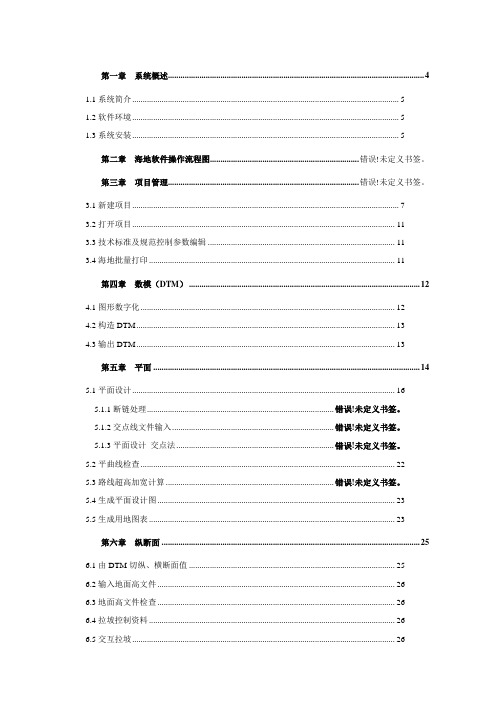
第一章系统概述 (4)1.1系统简介 (5)1.2软件环境 (5)1.3系统安装 (5)第二章海地软件操作流程图....................................................................... 错误!未定义书签。
第三章项目管理........................................................................................... 错误!未定义书签。
3.1新建项目 (7)3.2打开项目 (11)3.3技术标准及规范控制参数编辑 (11)3.4海地批量打印 (11)第四章数模(DTM) (12)4.1图形数字化 (12)4.2构造DTM (13)4.3输出DTM (13)第五章平面 (14)5.1平面设计 (16)5.1.1断链处理......................................................................................... 错误!未定义书签。
5.1.2交点线文件输入............................................................................. 错误!未定义书签。
5.1.3平面设计_交点法........................................................................... 错误!未定义书签。
5.2平曲线检查 (22)5.3路线超高加宽计算 ................................................................................ 错误!未定义书签。
5.4生成平面设计图 (23)5.5生成用地图表 (23)第六章纵断面 (25)6.1由DTM切纵、横断面值 (25)6.2输入地面高文件 (26)6.3地面高文件检查 (26)6.4拉坡控制资料 (26)6.5交互拉坡 (26)6.6拉坡修改 (27)6.7竖曲线设计 (27)6.8竖曲线检查 (28)6.9主要经济指标 (28)6.10工可国民经济评价 (29)6.10设计高程计算 (29)6.11生成纵断面图 (29)6.12生成纵坡表 (30)6.13生成路基设计表 (30)6.14平纵缩图 (30)6.15生成水准点表 (31)6.16生成超高计算表 (31)第七章横断面 .............................................................................................. 错误!未定义书签。
- 1、下载文档前请自行甄别文档内容的完整性,平台不提供额外的编辑、内容补充、找答案等附加服务。
- 2、"仅部分预览"的文档,不可在线预览部分如存在完整性等问题,可反馈申请退款(可完整预览的文档不适用该条件!)。
- 3、如文档侵犯您的权益,请联系客服反馈,我们会尽快为您处理(人工客服工作时间:9:00-18:30)。
Lazarus简明使用手册
1介绍
Lazarus是一个免费的使用Freepascal编译器作为后台编译器的pascal集成开发环境。
Lazarus由Pascal编写而成,界面风格类似Delphi,具有强大的程序开发功能。
图一是在运行中的Lazarus:
图一
图中,窗口1是主窗口,窗口2是对象属性窗口,窗口3是源码编辑窗口,窗口4是程序中的窗口布局。
在NOI比赛中,不会用到窗口2和窗口4。
2安装Lazarus
2.1获取Lazarus的RedHat Linux 9.0安装文件
当前版本Lazarus需要的安装文件有三个,它们是:fpc-1.9.8-0.i586.rpm、fpcsrc-1.9.8-050225.i386.rpm、lazarus-0.9.6-fpc_1.9.8_0.i386.rpm,这三个文件的下载地址分别为:
/lazarus/fpc-1.9.8-0.i586.rpm?download
/lazarus/fpcsrc-1.9.8-050225.i386.rpm?download /lazarus/lazarus-0.9.6-fpc_1.9.8_0.i386.rpm?down load
2.2在RedHat Linux 9.0上安装Lazarus
使用root用户登录Linux,在终端中进入安装文件所在目录,并输入如下命令安装Lazarus。
rpm –Uvh fpc-1.9.8-0.i586.rpm
rpm –Uvh fpcsrc-1.9.8-050225.i386.rpm
rpm –Uvh lazarus-0.9.6-fpc_1.9.8_0.i386.rpm
2.3在RedHat Linux 9.0上安装高版本的gdb
为使Lazarus在RedHat Linux 9.0下正确调试程序,需要安装高版本的gdb。
用户可以通过中国计算机学会的网站,下载gdb 6.3的RedHat Linux 9.0下的安装文件:gdb-6.3.0.0-1.10.i386.rpm。
使用root用户登录Linux,在终端中进入安装文件所在目录,并输入命令rpm –hUv gdb-6.3.0.0-1.10.i386.rpm
回车执行该命令安装gdb 6.3。
3初次使用Lazarus
3.1启动Lazarus
在终端中输入Lazarus命令,回车执行该命令即可以启动Lazarus集成开发环境。
3.2主窗口
在Lazarus界面的主窗口中,包含了主菜单,常用工具条。
如图二所示
图二
主菜单包括File(文件)、Edit(编辑)、Search(查找)、View(视图)、Project (工程)、Run(运行)、Components(组件)、Tools(工具)、Environment(环境)、Windows(窗口)、Help(帮助)。
在主窗口的左下角,有几个常用的工具按钮:新建文件;打开;保
存;保存全部;运行;步入;跳过。
3.3设置调试器
在主菜单中选择“Environment”->“Debugger Options”,出现调试器选项设置对话框,如图三所示。
在Debugger type and path下的下拉框中,选择GNU debugger (gdb),并下面的文本编辑框中,填入/usr/bin/gdb。
点击OK,确定。
图三
4建立程序
Lazarus下,采用“工程”来管理生成同一程序的源代码,因此在开始编写一个新的程序时,需要先为此程序建立一个工程。
4.1新建工程
从主菜单中选择,“File”->“New…”,此时会弹出如图四所示的对话框:
图四
选择Custom Program,并点击OK。
此时,将生成一个新的工程,且自动生成一个源程序模板,并在源码编辑窗口中显示该模版。
如图五所示:
图五
此时的工程名以及生成的源程序模板的文件名并不是用户所需要的,而且并未保存到磁盘上,因此,必须对此工程进行保存并将文件名改为所需要的名字。
选择主菜单“File”->“Save”,弹出保存对话框,如图六所示:
图六
选择指定保存的目录,并在填入工程名。
注意,工程名的主文件名必须为指定的程序名,并且,工程名必须以.lpi作为扩展名。
点击OK后,在指定保存的目录下,将保存两个文件,一个是工程文件,以.lpi作为扩展名;另一个是源代码文件,以.pas作为扩展名。
这两个文件的主文件名均为指定的程序名。
例如:比赛题目的名字叫game,那么在保存工程时,应该选择指定的目录(即选手竞赛用户主目录下的game目录),并输入game.lpi作为工程名。
在点击OK后,将在指定的目录下,出现game.lpi、game.pas 两个文件。
此时,可以在源码编辑窗口中开始编辑源码。
4.2编译建立程序
源代码文件编辑保存完成后,可以开始编译建立程序。
选择主菜单中的“Run”->“Build”,或者使用快捷键Ctrl+F9,即可开始编译创建程序。
在编译的过程中,将会弹出消息窗口,并在其中看到编译器输出的信息。
如果编译过程中出现错误,可以单击错误信息定位到源代码中对应的地方,如图七所示。
图七
如果正确地编译建立了程序,生成的可执行程序将存放在与源代码所在目录中。
程序名为源代码文件名的主文件名字,如:源代码文件名为test.pas,生成的可执行程序为test。
4.3运行程序
正确创建了可执行文件后,可以运行该程序观察运行结果是否正确。
点击主菜单“Run”->“Run”,或者使用快捷键F9,或者点击Lazarus主窗口中的按钮。
这时会启动一个终端窗口,并在其中运行创建的程序。
程序运行结束后,终端窗口等待用户输入回车键后关闭。
运行程序的情况如图八所示。
程序的往屏幕的输出将出现在启动Lazarus的终端上,并加上了[DBGTGT]的前缀。
注意:Lazarus运行时不能从标准输入(即键盘)输入,因此,如果需要用
到从键盘读入的操作,务必改成从文件中读入。
图八
5调试
5.1过程调试
过程调试包括“步入”(Step into)、“跳过”(Step over)、“执行到光标”(Run to cursor)三个调试操作,分别对应快捷键F7、F8、F4。
用户也可以通过点击主菜单“Run”中对应的菜单项,来完成相应的功能。
也可以点击Lazarus主窗口上的、来执行相应的操作。
5.2断点
程序断点的设置(取消)方法,如图九所示,在源代码编辑窗口中,点击希望设置(取消)断点的地方左部的行号区域,即可完成中断点的设置(取消)操作。
断点设置时,在源代码对应的地方,编辑窗口左侧有红色的断点标志,断点
取消后,该标志消失。
图九
5.3变量察看
Lazarus的变量察看功能分为两部分:局部变量察看、观测点察看。
5.3.1局部变量察看
局部变量察看功能在调试过程中,实时显示当前所在函数的局部变量的变化。
点击主菜单“View”->“Debug windows”->“Local Variables”,可显示局部变量察看窗口,如图十右下角所示。
5.3.2观测点察看
观测点察看功能在调试过程中,实时显示用户关心的变量或者表达式的值的变化。
点击主菜单“View”->“Debug windows”->“Watches”,可显示观测点察看窗口,如图十左下角所示:
用户可以在观测点察看窗口中右击鼠标,选择“Add”,并在随后的对话框中输入自己希望看到的变量或者表达式,确定后即将该变量或者表达式加入了观察项目中。
用户也可以选中已有的观测点并右击鼠标,选择“Delete”,
将选中的观测点去掉。
图十。