RL132规格说明书
艾森121732型号电子保护电路保护器说明书

Eaton 121732Eaton Moeller® series PKE12 Motor-protective circuit-breaker, Complete device with standard knob, Electronic, 1 - 4 A, With overload releaseGeneral specificationsEaton Moeller® series PKE System-protective circuit-breaker1217324015081195428101 mm 102.5 mm 45 mm 0.42 kg CE MarkedCSA Std. C22.2 No. 14-10 UL 508 EN 60947-4-1 IEC 60947-4-1 VDECSA-C22.2 No. 60947-4-1-14 IEC/EN 60947-4-1 IEC/EN 60947CSA Class No.: 3211-05 UL 60947-4-1 CSACSA File No.: 165628 ULUL Category Control No.: NLRV UL File No.: E36332 VDE 0660 CEProduct NameCatalog Number EANProduct Length/Depth Product Height Product Width Product Weight Compliances CertificationsModel CodeTurn buttonPhase-failure sensitivity (according to IEC/EN 60947-4-1, VDE 0660 Part 102)Standard knobMotor protection for heavy starting dutyPhase failure sensitiveOverload releaseMotor protectionThree-pole 500 (Class 5) AC-4 cycle operation, Main conducting paths Note: Going below the minimum current flow time can cause overheating of the load (motor).For all combinations with an SWD activation, you need not adhere to the minimum current flow times and minimum cut-out periods.900 (Class 15) AC-4 cycle operation, Main conducting paths 1000 (Class 20) AC-4 cycle operation, Main conducting paths 700 (Class 10) AC-4 cycle operation, Main conducting paths≤ 500 ms, main conducting paths, AC-4 cycle operationTerminals: IP00IP2050,000 operations (at 400V, AC-3)50,000 Operations (Main conducting paths)60 Operations/h1 A4 AIII3Motor protective circuit breakerFinger and back-of-hand proof, Protection against direct contact when actuated from front (EN 50274)6000 V ACActuator type FeaturesFitted with: FunctionsNumber of poles Current flow times - minCut-out periods - minDegree of protectionLifespan, electricalLifespan, mechanicalOperating frequencyOverload release current setting - min Overload release current setting - max Overvoltage categoryPollution degreeProduct categoryProtectionRated impulse withstand voltage (Uimp)Also motors with efficiency class IE3-25 - 55 °C, Operating range-5 - 40 °C to IEC/EN 60947, VDE 066025 g, Mechanical, according to IEC/EN 60068-2-27, Half-sinusoidal shock 10 msMax. 2000 m-25 °C55 °C-25 °C40 °C-40 °C80 °CDamp heat, constant, to IEC 60068-2-78Damp heat, cyclic, to IEC 60068-2-301 x (1 - 6) mm², ferrule to DIN 462282 x (1 - 6) mm², ferrule to DIN 462281 x (1 - 6) mm²2 x (1 - 6) mm²14 - 1010 mm 50 Hz 60 Hz 4 A0.75 kW1.5 kWSuitable forTemperature compensation Shock resistanceAltitudeAmbient operating temperature - minAmbient operating temperature - maxAmbient operating temperature (enclosed) - minAmbient operating temperature (enclosed) - maxAmbient storage temperature - minAmbient storage temperature - maxClimatic proofingTerminal capacity (flexible with ferrule) Terminal capacity (solid)Terminal capacity (solid/stranded AWG) Stripping length (main cable) Tightening torque Rated frequency - minRated frequency - maxRated operational current (Ie)Rated operational power at AC-3, 220/230 V, 50 Hz Rated operational power at AC-3, 380/400 V, 50 Hz1 Nm, Screw terminals, Control circuit cables 1.7 Nm, Screw terminals, Main cable690 V690 V4 A100 A, Class J, 600 V High Fault, max. Fuse, SCCR (UL/CSA) 100 kA, 600 V High Fault, Fuse, SCCR (UL/CSA)± 20% tolerance, Trip blocks Trip block fixed 15.5 x IrDelayed approx. 60 ms, Trip blocks Basic device fixed 15.5 x Iu, Trip Blocks4 A, AC-3 up to 690 V0.125 HP0.75 HP0.33 HP0.75 HP2 HP3 HPScrew terminals0.9 W0 W0.3 W4 ARated operational voltage (Ue) - min Rated operational voltage (Ue) - max Rated uninterrupted current (Iu)Short-circuit current rating (group protection)Short-circuit releaseSwitching capacity Assigned motor power at 115/120 V, 60 Hz, 1-phase Assigned motor power at 200/208 V, 60 Hz, 3-phase Assigned motor power at 230/240 V, 60 Hz, 1-phase Assigned motor power at 230/240 V, 60 Hz, 3-phase Assigned motor power at 460/480 V, 60 Hz, 3-phase Assigned motor power at 575/600 V, 60 Hz, 3-phase Connection Equipment heat dissipation, current-dependent Pvid Heat dissipation capacity Pdiss Heat dissipation per pole, current-dependent Pvid Rated operational current for specified heat dissipation (In)Static heat dissipation, non-current-dependent Pvs0 WMeets the product standard's requirements.Meets the product standard's requirements.Meets the product standard's requirements.Meets the product standard's requirements.Meets the product standard's requirements.Does not apply, since the entire switchgear needs to be evaluated.Does not apply, since the entire switchgear needs to be evaluated.Meets the product standard's requirements.Does not apply, since the entire switchgear needs to be evaluated.Meets the product standard's requirements.Does not apply, since the entire switchgear needs to be evaluated.Does not apply, since the entire switchgear needs to be evaluated.Is the panel builder's responsibility.Is the panel builder's responsibility.Is the panel builder's responsibility.Motor Starters in System xStart - brochureMotor-Protective Circuit-Breaker PKE - brochurePKE – Communication module Modbus RTUProduct Range Catalog Switching and protecting motorseaton-manual-motor-starters-pke65-characteristic-curve.eps eaton-manual-motor-starters-pke65-characteristic-curve-003.eps eaton-manual-motor-starters-pke65-characteristic-curve-005.epsDA-DC-00004945.pdfDA-DC-00004950.pdfeaton-manual-motor-starters-dimensions-002.epseaton-manual-motor-starters-3d-drawing-002.epseaton-manual-motor-starters-mounting-3d-drawing.epseaton-general-ie-ready-dilm-contactor-standards.epsETN.PKE12_XTU-4IL034011ZUIL034003ZUIL03402019ZVideo Motor Protective Circuit Breaker PKEWIN-WIN with push-in technologyMN03402004Z_DE_ENDA-CD-pke12_xtuDA-CS-pke12_xtu10.2.2 Corrosion resistance10.2.3.1 Verification of thermal stability of enclosures10.2.3.2 Verification of resistance of insulating materials to normal heat10.2.3.3 Resist. of insul. mat. to abnormal heat/fire by internal elect. effects10.2.4 Resistance to ultra-violet (UV) radiation10.2.5 Lifting10.2.6 Mechanical impact10.2.7 Inscriptions10.3 Degree of protection of assemblies10.4 Clearances and creepage distances10.5 Protection against electric shock10.6 Incorporation of switching devices and components10.7 Internal electrical circuits and connections10.8 Connections for external conductors10.9.2 Power-frequency electric strength10.9.3 Impulse withstand voltage BrochuresCatalogues Characteristic curveDeclarations of conformity DrawingseCAD modelInstallation instructionsInstallation videos Manuals and user guides mCAD modelEaton Corporation plc Eaton House30 Pembroke Road Dublin 4, Ireland © 2023 Eaton. All rights reserved. Eaton is a registered trademark.All other trademarks areproperty of their respectiveowners./socialmediaIs the panel builder's responsibility.Is the panel builder's responsibility.The panel builder is responsible for the temperature rise calculation. Eaton will provide heat dissipation data for the devices.Is the panel builder's responsibility. The specifications for the switchgear must be observed.Is the panel builder's responsibility. The specifications for the switchgear must be observed.The device meets the requirements, provided the information in the instruction leaflet (IL) is observed.10.9.4 Testing of enclosures made of insulating material 10.10 Temperature rise10.11 Short-circuit rating10.12 Electromagnetic compatibility10.13 Mechanical function。
12路调音台湖山说明书
DM0804BDM1204BDM1604B---用户手册警告标志:机箱上的警告标志告诉用户不能擅自打开机箱,否则可能造成人身伤害阳插头立体声/耳机插头TRS单声通道耳机插头阴插头前置(Pre)后置(Post)“前置衰减器”信号取自通道衰减器之前的某点,因此发送的电平仅受AUX发送电平控制的影响,而不受通道衰减器的影响。
前置衰减器发送信号在监控混音中最常用。
“后置衰减器”信号取自通道衰减器之后的某点,因此其电平同时受AUX发送电平控制和通道衰减器的影响。
后置衰减器发送信号经常与调音台AUX或外接效果处理的效应器返回信号一起使用。
频率带类型基础频率最大削弱/增强HIGH(高)斜坡10KHzMID(中)峰值250Hz-5KHz (可变)LOW(低)斜坡100Hz+15dB频率带类型基础频率最大削弱/增强HIGH(高)斜坡10KHzHI-MID(高-中)峰值3KHzLO-MID(低-中)峰值800HzLOW(低)斜坡100Hz+15dB效果模式英文名中文名1Small Hall A小厅堂A2Small Hall B小厅堂B3Large Hall A大厅堂A4Large Hall B大厅堂B5Short RoomA小房间A6Short Room B小房间B7RoomA房间A8Room B房间B9Church A教堂A10Church B教堂B11Cathedral A大教堂A12Cathedral B大教堂B13Forward Gate前转门14Reverse Gate A反相门A15Reverse Gate B反相门B16Left to Right Gate左转右门17Mono Echo单声道回声18Stereo Echo立体声回声19Mono Triplet Echo单声道三重回声20Stereo Triplet Echo立体声三重回声21Chorus Light1轻度合唱22Chorus Medium1中度合唱123Chorus Mdeium2中度合唱224Chorus Deep1深度合唱25.Chorus Fast1快速合唱26.Long Time Chorus长时间合唱27.Leslie Slow慢速丽丝28.Leslie Fast快速丽丝29.Flange Light1轻度法兰30.Flange Medium1中度法兰31.Slow Flange慢速法兰32.Flange Deep深度法兰33Short Delay Stereo立体声短延时34Short Delay Feedback Mono单声道短延时35Metal金属36Sharp锐利37Heavy沉重38Down Oct向下变调39Light Detune轻度失谐40Deep Detune深度失谐41Chorus+Room合唱+房间42Chorus+Hall合唱+大厅43Leslie+Hall丽丝+大厅44Leslie+Room丽丝+房间45Flange+Room法兰+房间46Flange+Hall法兰+大厅47Chorus+Delay合唱+延时48Short Delay+Reverb延时+混响27■安装.1将两个金属安装支架支撑用螺丝固定在本装置上。
132标准及新品使用说明书

三一重型装备有限公司由三一集团全资兴建,是一家从事研发、生产大型煤炭机械综合成套设备制造企业,致力于用高新技术改造落后、传统的煤炭采掘机械,并促使其迅速升级换代至世界一流水准。
借助集团的支持,我们将其它领域机、电、液先进的技术借鉴到煤炭机械,成为行业技术的引领者,产品有综掘、综采、矿用车辆、电机等。
三一重型装备的研发团队有700余人,集中了行业内最优秀的工程师,是业内最具规模的研究机构。
他们以“安全、可靠、高效、人性化”为核心设计理念,以赶超标杆企业为设计目标,不断地在颠覆行业标准。
公司已经申请国家专利 180余项,一系列新技术和新专利的诞生,带动着企业不断迈向新的高度。
2008年,三一成功推出全硬岩综掘成套装备 、EBZ半煤岩综掘成套装备、联合采煤机组成套装备、矿用混凝土泵送成套装备、房柱式采煤成套装备、自动化刨煤机组成套装备 、掘辅一体化成套装备、矿用辅运车辆成套装备等8大成套装备,成为国内第一家煤炭机械成套设备供应商。
并已成功销往神华蒙西、辽宁铁法、山西朔州等煤炭生产企业。
服务是三一的核心竞争力之一。
秉承“创造客户价值”的服务理念,以客户需求为中心,打造行业第一的 ECC控制中心,贯穿于企业主要业务流程的一整套业务协作平台。
三一人时刻在心中记挂“一切为了客户”,并创新的提出了“一切问题都是三一的”服务理念,几十个服务网点和配件中心,遍布全国各大煤炭产区,每一个服务站都贴近矿区。
“绿色通道”制度保证配件和服务工程师第一时间无条件到达现场。
为满足客户需求,三一成立操作手俱乐部,免费向客户提供专业技能培训,并启动“十年万名操作手培训班”计划、 “十年千名矿长深造项目”。
三一重型装备立志在未来的三五年内挤身于国际顶尖煤炭机械制造企业之列,成为国内煤炭机械行业内一流成套设备供应商和标志性企业,产品全面替代进口!用集团董事长梁稳根先生的话讲,“在不久的将来世界最好的煤机不是由美国制造,也不是由德国制造,而是应该由中国制造,由三一制造。
SPL120 120L 120RM3 SPL162 声压级测量仪 使用说明书
OPERATORS MANUAL Model SPL120/120L/120RM3/SPL162 Sound Pressure Level MetersGENERAL:GOLD LINE Sound Pressure Level Meters are precision instruments designed to measure continuous sound. They feature a digital numeric display that can easily be read from a distance. The digital display reads both fast and slow inputs without the need for a "slow" switch setting as in metered units. Sound level readings are based on ANSI S1.4 standards as published in the American National Standards for sound level meters.Sound level readings are provided in either "FLAT", IEC "A" or "C" weighting. The SPL120 series meters were designed for general field use such as measurement of typical levels produced by environmental and industrial noise. Applications include OSHA compliance, enforcement of noise statutes, setting noise levels of sound systems or monitoring clubs and discos. Additional CONTRACTOR and THEATER applications include setting DOLBY LEVELS and insuring that speakers are set to proper levels.Model SPL120/SPL162: A portable, battery operated sound level meter with built-in microphone. Each includes a HI SPL function switch that shows the highest SPL reading monitored. The HOLD function will freeze the display when the ON/OFF switch is moved to the HOLD position. The calibration of the either can be verified and adjusted in the field by inserting the microphone into an acoustic calibrator fitted for a ½" diameter microphone and adjusting a calibration potentiometer on the side of the unit.Model SPL120L: The SPL120L (low level) is provided with a detachable microphone, Model MK8. The MK8 attaches directly to the SPL120L via the XLR microphone input jack, or can be remoted via a microphone cable. The length of cable is not critical and will not effect the SPL readings with a cable length of up to 100 feet. The SPL120L has a built-in attentuator circuit that extends the sensitivity of the unit allowing for the measurement of lower level signals. For SPL’s of 65dB or greater, the far left switch is set to ON and the SPL is read directly from the readout. For SPL’s less than 65dB SPL, set the far left switch to -20dB, then subtract 20 from the reading shown.Model SPL120RM3:A Rack Mounted SPL Meter switchable for 3 microphones is perfect for live sound applications. It allows you to place one mic near the mixer, one mic on the stage, and one mic in the audience. This allows the sound engineer to easily switch to any of the three microphones and monitor sound levels at each of these positions. The SPL120RM3 is supplied with three MK8 microphones. Three XLR MICROPHONE INPUTS are provided on the rear panel.SPECIFICATIONSMODELS SPL120 / SPL120L / SPL162MEASUREMENT RANGE:SPL120 - Microphone input: 47dB - 123dB SPLSPL120L - Microphone input: 35dB - 123dB SPLSPL120/120L - Line input: -70dBm to +5dBmSPL162 - Microphone input: 100dB - 162dB SPLSPL162 - Line input: -60dBm to +10dBmINPUTS: SPL120/162 - Microphone: Built-in omnidirectional electret condenser.SPL120L - Microphone: Detachable 600Ω omnidirectional electret condenser. Model MK8.SPL120/120L/162 - Line: Unbalanced 3.5mDISPLAY: Four digit via 7 segment display.RANGE SWITCH: SPL for normal response; HI SPL to capture highest SPL measured.WEIGHTING: IEC A, C and FLAT.TIME WEIGHTING: rms fast.ATTACK TIME: 0.15s.APPROVALS: Emissions: - EN 55022 B - FCC Class BImmunity: - EN 55024 BPOWER REQUIREMENTS:Batteries - Eight AA alkaline or nicad.********************************Internal switch must be set to NICAD when recharging NICAD batteries.BATTERY LOW INDICATOR: Unit will read 00.1 on display.SIZE (W x H x D); WEIGHT: 3," x 8" x 2,"; 12 oz.CASE MATERIAL: High impact ABS.MODEL SPL120RM3MEASUREMENT RANGE: 47dB - 123dB SPLINPUTS: Three - XLR 3 pin receptacles available, selectable by front panel switch.Unit supplied with (3) three Model MK8 600Ω omnidirectional electretcondenser microphones.DISPLAY: Four digit via 7 segment display.WEIGHTING: IEC A, C and FLAT. Internally selectable.TIME WEIGHTING: rms Fast.ATTACK TIME: 0.15s.APPROVALS:Emissions: - EN 55022 B - FCC Class BImmunity: - EN 55024 BPOWER REQUIREMENTS:********************************.(Poweradaptersupplied)SIZE (W x H x D); WEIGHT: 19" x 1.75" x 4½"; 24 oz.CASE MATERIAL: Painted aluminum.This equipment has been tested and found to comply with the limits for a Class B digital device, pursuant to Part 15 of the FCC Rules. These limits are designed to provide reasonable protection against harmful interference in a residential installation. This equipment generates, uses and can radiate radio frequency energy and, if not installed and used in accordance with the instructions, may cause harmful interference to radio communications. However, there is no guarantee that interference will not occur in a particular installation. If this equipment does cause harmful interference to radio or television reception, which can be determined by turning the equipment off and on, the user is encouraged to try to correct the interference by one or more of the following measures:-Reorient or relocate the receiving antenna.-Increase the separation between the equipment and receiver.-Connect the equipment into an outlet on a circuit different from that to which the receiver is connected.-Consult the dealer or an experienced radio/TV technician for help.Pursuant to Part 15 of the FCC rules, any changes or modifications not expressly approved by Gold Line may cause harmful interference and void the FCC authorization to operate the equipment.WARRANTY and Factory ServiceGOLD LINE products are proudly made in the USA and are covered by a one year limited warranty. For details of this warranty, consult the enclosed warranty registration card or your local dealer.GOLD LINE Customer Service will help you get the most from your new SPL meter. For answers to questions regarding use of the unit, or for information not covered in this manual, please write us. If you are experiencing difficulties with your SPL meter, please consult your dealer regarding factory service. If factory service is needed, you may call or fax us between 9:00am and 4:30pm US Eastern Time for instructions and a return authorization.Enter your serial#_______________date of purchase_______________12-504 m_spl_4g01.docBox 500 West Redding, CT. 06896 203-938-2588 phone - 203-938-8740 faxhttp://******************************************。
SUNFAR M320变频器说明书(免费下载)
TYPE: SOURCE: OUTPUT: SERIAL No.:
M320-4T0220 3PH 380V 50/60Hz 29.6KVA 45A 0123456789
变频器型号 额定输入电压相数、电压及频率 额定输出容量及电流 产品序列号 条形码
图-1 变频器铭牌数据 本公司在产品的制造、包装、运输等方面有严格的质量保证体系,但万一发生某种疏漏,请 速与本公司或当地的代理商联系,我们将在第一时间为您解决问题。
操作面板 上盖板
下盖板
控制回路端子 主回路端子
图 1-2 Ⅱ类变频器部件名称 适用机型: M320-4T0110~M320-4T0900 / M320-2T0055~M320-2T0550
1.3 变频器系列型号
变频器型号
额定容量(KVA)
M320-2T0015
2.9
M320-2T0022
3.8
M320-2T0037
5.7
M320-2T0055
9.5
M320-2T0075
12.6
M320-2T0110
17.5
M320-2T0150
22.9
M320-2T0185
28.6
M320-2T0220
32.4
M320-2T0300
41.9
M320-2T0370
51.5
M320-2T0450
64.8
M320-2T0550
78.1
产品介绍 1
功率等级(KW)
0015
1.5
0022
2.2
0037
3.7
0055
5.5
0075
7.5
0110
11
.
时代 TH132 一体化里氏硬度计 使用说明书

时代TH132一体化里氏硬度计使用说明书目录第一章简介1.1概述1.2时代TH132一体化里氏硬度计各部分名称1.3主要用途1.4技术参数1.5测量范围第二章试件的准备2.1概述2.2测量槽、内外圆柱面和球面2.3薄、轻试件的支承与耦合第三章操作方法3.1按键功能及显示3.2存储器的应用和内容打印3.2.1显示存储器内容3.2.2打印存储器内容3.2.3删除存储器内容3.3测量第四章保养与维修4.1保养4.2维修附1:用户须知附2:非保修件清单第一章简介1.1概述时代TH132一体化里氏硬度计(以下简称硬度计)是一种先进的一体化硬度检测仪器,具有结构紧凑、测量精度高、测量范围宽、便于携带和易于操作等优点,广泛用于测试钢、铸钢及合金工具钢等金属,尤其适合薄轻试件的测试。
该硬度计集C型冲击装置和数据处理装置于一身。
能换算出维氏、布氏、洛氏C或肖氏硬度值,并可选择三个冲击方向,即0°、 45°、 90°,如图2。
如果与打印机相连,则可实现在线打印和脱机打印。
可选用异型支承环,以测量内处圆柱和球表面的硬度。
1. 2时代TH132一体化里氏硬度计各部分名称(见图1)1、冲击装置2、充电插口3、打印机接口4、液晶5、功能键设置6、电源开关7、释放按钮8、外套9、支撑环 10、加载键图 1注:本硬度计随机附件有试块、仪器盒、充电器、尼龙刷、小支承环及说明书等。
1.3主要用途·直接测量大型和(或)重型的试件·已安装的机械或永久性组装的部件·金属材料仓库的材料区分·大型工件的狭小空间等·更适合薄、轻以及带表面硬化层等零件的测量1.4技数参数硬度制: HRC、HV、HS、HLC、HB外形尺寸: 155×24×55(mm)冲击装置: C1型冲击能量: 2.7N·mm球头:碳化钨精度:示值相对误差±1%;示值重复性相对误差1%(对应860HLC标准硬度试块)重量: 180g工作时间:持续使用8h充电时间:直流9V,75mA大于8h冲击方向: 0°,45°,90°工作温度: 0~45℃1.5测量范围图 2第二章试件的准备2.1概述为了减少试件表面粗糙度对测量结果的影响,被测表面应足够光滑,表面粗糙度Ra值不超过0.4μm试件表面应干净且无油污。
迈卡尔多X12i 12英寸高效专业扬音器说明书
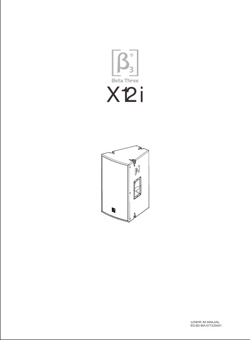
124514CONTENTSFEATURES ACOUSTIC CHARTS INSTALLATION DIMENSIONS SPECIFICATION LIMITED WARRANTY45Hz-18kHz95dB1.8kHz 300W 8Ω<3%NL4×2,1+ 1- 27.5kg 30.0kg402×440×650mm 550×510×770mmSPECIFICATIONTransducerSensitivity(1W/1m)Frequency response(-3dB)THDNet Weight Gross Weight Dimension(W ×D ×H)Packing Dimension(W ×D ×H)Crossover Point Rated Power (RMS )Rated Impedance Input Connectors Dispersion (H ×V )◇ 12" high efficient professional speaker with unique LF extension technology, the LF can be lower to 35Hz(SPL-10dB).◇ Computer optimized simulation design make sure the good frequency response and excellent phase feature.◇ Two transducers two way full range speaker with Hi-Fi level performance ◇ One 12 professional woofer."◇ One compression driver with 3" magnalium diaphragm. ◇ 60°X60° wide dispersion horn.◇ Independent crossover circuit for woofer and tweeter, low distortion and interferer.◇ Single Amplifier driving mode.◇ Suitable for the application in rock bar, night club, living performance and portable sound system.FEATUREB3 X series speaker is mainly designed for all kinds of rock bar, entertainment bar, club, all kinds of living performance, and portable sound reinforcement applications.12 inch full range and 15 inch full range speakers are trapeziform design; it will be very convenient tomake an array. Selected highintensity plywood has enough strength and can absorb the noise of resonance. Standard mounting&flying system and SPK socket are very easy for the installation and connection. X Series products are developed and produced by combination of the latest computer stimulation design technology, the latest loudspeaker material and manufacturing technology. All transducers adopt the optimized magnetic circuit having high magnetic energy, low distortion and excellent ventilation/cooling system. LF uses nonlinear thickness long fabric paper cone with waterproof feature and special damping Glue treated, and high power sandwich type voice coil. HF adopts high temperature treated magnalium diaphragm, voice coil with copper cladding aluminum wire and compression cavity designed with linear phase technology. Wide dispersion horn makes sure the excellent sound coverage. The patented HF protection circuit grantee the high reliability and low distortion.INTRODUCTIONHF: 3" x 1, LF: 12" x 1119/125dB(Peak)Max. SPL 60° x 60°2 501 002 005 001k2k5k1 0k2 0k20Hz1 1 0d B 1 8 0°D eg1 0 0 1 0 8°9 0 3 6°8 0 - 3 6°7 0 - 1 08°6 0- 1 80°C L20 Hz501002005001K 2K 5K 10K 20KOhm678910203040506070Impedance vs FreqFREQUENCY/RESPONSEPHASE IMPEDANCE RESPONSE-LFFREQUENCY RESPONSEPHASE RESPONSE650m m402mm440mm300m m321mmBack viewSide view Front viewTop viewDIMENSIONSINSTALLATIONLIMITED WARRANTYIf malfunction occurs during the specified warranty period from the date of original purchase,the product will be repaired or replaced without charge by Elder Audio.The Limited Warranty does not apply to:(a)exterior finish or appearance;(b)certain specific items described in the individual product data sheet or owner's manual;(c)malfunction resulting from use or operation of the product other than as specified in theindividual product data sheet or owner's manual;(d)malfunction resulting from misuse or abuse of the product;(e)malfunction occurring at any time after repairs have been made to the product by anyoneother than Elder Audio Service or any of its authorized service representatives.To obtain warranty service, customer must deliver proof of purchase of the product in the form of a bill of sale or receipt invoice.X12i Speakers and Speaker Systems are guaranteed against malfunction due to defects inmaterials or workmanship for a period of three (3) years from the date of original purchase. The Limited Warranty does not apply to burned voice coils or malfunctions such as cone and/or coil damage resulting from improperly designed enclosures. Additional details are included in theLimited Warranty statement.X12i Accessories are guaranteed against malfunction due to defects in materials or workmanship for a period of one (1) year from the date of original purchase. Additional details are included in the Limited Warranty statement. .X12i Flying Hardware (including enclosure-mounted hardware and rigging accessories) isguaranteed against malfunction due to defects in materials or workmanship for a period of one(1) year from the date of original purchase. Additional details are included in the Limited Warrantystatement.Specifications are subject to change without notice.。
E12 3MP Cube带基本WDR,固定镜头硬件用户手册(PoE)说明书

E123MP Cube with Basic WDR, Fixed lens Hardware User’s Manual(PoE)Ver. 2012/10/22Table of Contents0.Precautions 31.Introduction 4Package Contents (4)Features and Benefits (5)Safety Instructions (6)Physical description (8)Basic Connections (9)Product Specification (10)2.Accessing Camera 11If you have DHCP server / router in your network: (11)If you do NOT have DHCP server / router in your network: (11)2Read these instructionsY ou should read all the safety and operating instructions before using this product.Heed all warningsY ou must adhere to all the warnings on the product and in the instruction manual. Failure to follow the safety instruction given may directly endanger people, cause damage to the system or to other equipment.ServicingDo not attempt to service this video device yourself as opening or removing covers may expose you to dangerous voltage or other hazards. Refer all servicing to qualified service personnel.TrademarksAll names used in this manual are probably registered trademarks of respective companies.LiabilityEvery reasonable care has been taken during the writing of this manual. Please inform your local office if you find any inaccuracies or omissions. We cannot be held responsible for any typographical or technical errors and reserve the right to make changes to the product and manuals without prior notice.FCC/CE RegulationNOTE: This equipment has been tested and found to comply with the limits for a Class A digital device, pursuant to Part 15 of the FCC Rules. These limits are designed to provide reasonable protection against harmful interference when the equipment is operated in a commercial environment. This equipment generates, uses, and can radiate radio frequency energy and, if not installed and used in accordance with the instruction manual, may cause harmful interference to radio communications. Operation of this equipment in a residential area is likely to cause harmful interference in which case the users will be required to correct the interference at their own expense.34Package ContentsE12Camera StandAccessories Warranty CardQIGFeatures and BenefitsThis is a cutting-edge digital video surveillance camera. It can compress and transmit real time images with outstanding image quality through a standard TCP/IP network. This camera is your best choice to build an intelligent IP surveillance system.H.264 High Profile/MJPEG Multi-Codec Dual StreamingThis device supports 2 compression formats, H.264 High Profile and MJPEG. It brings superior image quality at 15 frames per second up to resolution of 2048 x 1536 pixels. In Full HD 1080p (1920 x 1080), 720p (1280 x 720) and VGA resolution (640 x 480) the device reaches 30 frames per second.Built-in Hardware Motion DetectionNo more external motion sensors are required. Y ou may assign up to 3 video motion detection areas. By tuning the object size and sensitivity, it will reliably detect objects passing though is view. Hardware motion detection also offers better sensitivity and faster response time than software motion detection.Powerful Bundled Surveillance SoftwareTo extend the capabilities of the IP Camera series, a powerful surveillance program is included in the package for free. Users can easily use an existing PC as a digital video recorder. Scheduled recording and manual recording keep every important video recorded in the local hard disk. Reliable and accurate motion detection with instant warning enables immediate response in every condition. Quick and simple search and playback function lets you easily find the images and video you want.Software Development Kit SupportThis IP Camera can be integrated or controlled by applications from third party software developers. Software developers can save considerable efforts by using our Streaming Library or ActiveX control. Please contact us for details on integration support.5Safety InstructionsDon’t open the housing of the productCleaningDisconnect this video product from the power supply before cleaning.AttachmentsDo not use attachments not recommended by the video product manufacturer as they may cause hazards.Water and MoistureDo not use this video product near water, for example, near a bathtub, washbowl, kitchen sink, or laundry tub, in a wet basement, or near a swimming pool and the like.Don’t use accessories not recommended by the manufacturerOnly install this device in a dry place protected from weatherServicingDo not attempt to service this video product yourself as opening or removing covers may expose you to dangerous voltage or other hazards. Refer all servicing to qualified service personnel.Damage Requiring serviceDisconnect this video product from the power supply immediately and refer servicing to qualified service personnel under the following conditions.1) When the power-supply cord or plug is damaged2) If liquid has been spilled, or objects have fallen into the video product.3) If the video product has been directly exposed to rain or water.4) If the video product does not operate normally by following the operating Instructions inthis manual. Adjust only those controls that are covered by the instruction manual, as an improper adjustment of other controls may result in damage, and will often requireextensive work by a qualified technician to restore the video product to its normaloperation.6Safety CheckUpon completion of any service or repairs to this video product, ask the service technician to perform safety checks to determine if the video product is in proper operating condition.7Physical description1) Built-in Microphone2) Audio OutputThe IP device supports audio output with earphone jack3) Reset ButtonStep 1: Press and continue to hold the Reset Button for 15 seconds (with a sharp tipped object, like a pen.) after the unit has successfully completed the boot process.Step 2: The Ethernet LED light will turn off for about 1~2 seconds and flash on for another second. By this time the reset to default operation is already completed. Y ou may then releasethe reset button. This length of time fluctuates slightly with the environment. The unit will come back on and stay on after a few more seconds. The unit will start up with factory defaultsettings automatically.4) Ethernet PortThe IP device connects to the Ethernet via a standard RJ45 connector. Supporting NWAY, thisIP device can auto detect the speed of local network segment (10Base-T/100Base-TX Ethernet).8Basic ConnectionsFollow the procedures below to connect the IP device to the respective apparatuses.Please use a PoE (Power over Ethernet) supported switch or injector:1) Connect your IP Camera to the PoE Switch / Injector by CA T5 or CA T6 cables with RJ45connector.2) Connect your PoE Switch / Injector to PC with another CA T5 / CA T6 network cable.9Product Specification102.Accessing CameraIf you have DHCP server / router in your network:Many network server / routers are able to automatically provide IP addresses through DHCP. If you are using such a network, just plug in your computer and IP Camera into the network and your IP device will acquire network address by itself. Find and access the device with our IP Utility program. Y ou may download it at:/product/detail/Software/ACTi_Utility_SuiteIf you do NOT have DHCP server / router in your network:1. Configure your PC to use the same subnet by changing your PC’s IP address to thesubnet with prefix 192.168.0.XXX. The last number should be anything from 1 to 254except 100 and other occupied IP addresses. Subnet mask should be 255.555.255.0.2. The default IP used by this device is 192.168.0.100. Please make sure your PC isNOT using this address and that no two equipments use the same IP address in the network.3. Change your IP address by going to Control Panel ->Manage Network Connections ->Right click on the connection to change -> Option -> TCP/IP IPv4 Properties.11124. Open Internet Explorer (Version 6.0 or above) , and type in the Default IP:192.168.0.1005. When you see the login window, please input default user and password:Default User: Admin Password: 123456Please set the settings as below. ●● IP address: 192.168. 0.xxx ●Subnet mask: 255.255.255.(NOTE : xxx should be a number from 1 to 254 except 100, which is used by the IP device. Please also make sure that no two equipmentsuse the same IP address in the136. After logging in, you will see the video from camera. To go to the main menu, click the“Setup” button on the top left.If you are using a single camera, this is enough to access the device.If you are using multiple devices, you need to change the current device to another unused IP address, so that when the next device is connected to the network, no two devices use the same IP . Please perform the following steps.7. Go to IP Settings -> Connection Type8. Change the IP mode to Static.9. Change the IP to 192.168.0.101 or any other unused IPs. Do NOT use the PC ’s IPaddress or 192.168.0.100.). If this is not the first device you add to the network, please also avoid other devices ’IPs.1410. Click “Apply ”11. Please go to System -> Save & Reboot, and click “Apply ”. Internet Explorer will closeafter a few seconds. This is normal.12. Wait for 30 seconds, and open IE again to connect to the new IP . (In this example,192.168.0.101). For the second device or more you add into the network, please type the correct IP .13. Adjust the default Video setting by going to Video -> VideoPlease refer the firmware manual for the detail information.。
- 1、下载文档前请自行甄别文档内容的完整性,平台不提供额外的编辑、内容补充、找答案等附加服务。
- 2、"仅部分预览"的文档,不可在线预览部分如存在完整性等问题,可反馈申请退款(可完整预览的文档不适用该条件!)。
- 3、如文档侵犯您的权益,请联系客服反馈,我们会尽快为您处理(人工客服工作时间:9:00-18:30)。
! 安全注意事项
● 使用前,请务必仔细阅读本规格说明 书,再正确使用。
● 本规格说明书所记载的产品是供产业使用的机械设备。 请确认附录使用说明书上记载的使用条件。 有关设备的安装、运转、保养或者对使用材料的处理,有时会受当地法律规定 所限制。
● 在使用本产品时,无论是在运转时还是停止时,请仔细确认附录的使用说明书 及设备的警告显示后,再进行操作和保养。 如果因疏忽致使安全功能失效,会导致受伤、触电或故障。
4. 机械的构成 ............................................................................................................... 7
4.1 整体图............................................................................................................................ 7 4.2 元件供给部 .................................................................................................................... 8 4.3 元件供给部 2 分割方式 (只对应 NM-EJR6A) .............................................................. 10 4.4 元件插入部 .................................................................................................................. 11 4.5 铁砧规格 ...................................................................................................................... 13 4.6 基板识别补正功能........................................................................................................ 15 4.7 自动恢复功能............................................................................................................... 18
7. 机械指令以及EMC指令的适合模型以外的产品,禁止带入EU和销售。
8. 本规格说明书所记载的技术情报,是为了说明产品的主要动作和应用的资料,并不是在使用时对本 公司以及第三者的知识产权以及其它权利的保证,或者实施权的承诺。并且,根据客户的要求以及 信息,本公司所开发出的产品专利等工业所有权、著作权以及涉及到其它无形产权等,归本公司保 留。
8. 标准主体构成.......................................................................................................... 77
9. 选购件..................................................................................................................... 78
5. 插入元件规格.......................................................................................................... 19
5.1 元件尺寸和编带规格 .................................................................................................... 19
6. 印刷基板设计基准................................................................................................... 50
6.1 印刷基板规格概要........................................................................................................ 50 6.2 印刷基板精度............................................................................................................... 51 6.3 基板死区 ...................................................................................................................... 51 6.4 基板端部的插入范围 .................................................................................................... 52 6.5 基板形状 ...................................................................................................................... 57 6.6 基板流向 ...................................................................................................................... 57 6.7 基板上的邻接条件........................................................................................................ 57 6.8 基板下的邻接条件........................................................................................................ 58 6.9 基板下的邻接条件 (铁砧死区和元件邻接条件)............................................................ 59
73
・ 修订记载内容 ・ 追加选购件(SMEMA(A), SMEMA(B))
P. 21~49
修订元件尺寸和编带规格
Ver. 2012.0903
P. 5
追加环境条件(湿度、高度)
RL132 2012.0903
目录
1. 概要 .......................................................................................................................... 1
Ver. 2012.0903
规格说明书
【 电子元件实装系统 】
高速径向元件插件机
机种名 : 32
型 号 : NM-EJR5A NM-EJR6A
有关本规格说明书的注意事项
请注意以下各项内容。
1. 禁止任意复制或转载本资料的部分或者全部内容。
2. 由于机器和软件的改善,资料可能会在没有通知的情况下进行更改,请周知。
修订履历
本技术资料的记载内容,为最下列表格所注明的修订日期的内容。
修订日期 2011.02.01 2011.05.01 2011.07.01 2012.09.03
版本
相应页数
修订内容
Ver. 2011.0201 Ver. 2011.0501 Ver. 2011.0701
—
初版
P. 13, 14, 21, 22, 52, 59, 68, 69, 72,
7. 标准功能 ................................................................................................................. 76
7.1 程序功能 ...................................................................................................................... 76 7.2 三色信号塔 .................................................................................................................. 76 7.3 LAN ............................................................................................................................. 76
3. 如对本资料有不明之处,请与本公司联系。
4. 在使用时,请详细了解本设备及软件的规格和限制后再进行。由于错误操作所导致的损害,本公司 概不承担任何责任。