技嘉GA-EP41-UD3L主板说明书
主板说明书2
AM3 CPU 简介
记得使用一些散热胶涂在 CPU 表面, 使它更好的散热。
金色箭头
113
请根据以下步骤正确安装CPU和风扇。错误的安装可 能会引起您CPU和主板的损坏。 . 将拉杆从插槽上拉起,确认与插槽成90度角 2. 寻找CPU上的金色箭头,金色箭头方向如图所
示,只有方向正确CPU才能插入。 . 如果CPU是正确安装的,针脚应该完全嵌入进插
1.+23.+3.33.G4V.3.r+5Vo.5uG6Vn.r7+do.5uG8Vn.rP9do.Wu51nV0R1d.S1+O1B.1+K2211.V+3213.V+4.133.-5V.113.2G6V1V.rP7o1.SuG81-n.rO9Gdo2.NurG0o2n#.ruR1do2n.eu+2ds2n5.+3dV2.5+4V5.GVround
110
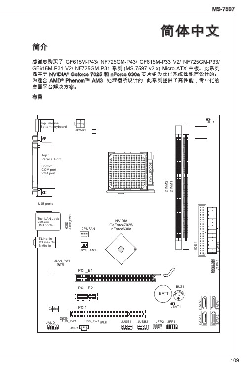
接口 ■ 后置面板
‑ 1 个 PS/2 鼠标端口 ‑ 1 个 PS/2 键盘端口 ‑ 1 个 COM 端口 ‑ 1 个 VGA 端口 ‑ 1 个 并行端口支持 SPP/EPP/ECP 模式 ‑ 1 个 LAN 插口 ‑ 4 个 USB 2.0 端口 ‑ 3 个 灵活的音频插口 ■ 板载周边接口 ‑ 2 个 USB 2.0 接口 ‑ 1 个 S/PDIF-Out 接口 ‑ 1 个 前置面板音频接口 ‑ 1 个 TPM 接口 ‑ 1 个 机箱入侵接口
触点
缺口
注意 * 在双通道模式下,一定要使用同类型同密度的内存模块,插入不同的内存插槽
中。 * 要成功的启动系统,必须首先将内存模块插入DIMM1插槽中。
115
ATX 24-Pin 电源接口: JPWR1 此接口可连接ATX 24-Pin电源适配器。在与ATX 24-Pin电源适配器相连时,请务 必确认,电源适配器的接头安装方向正确,针脚对应顺序也准确无误。将电源接 头插入,并使其与主板电源接口稳固连接。
N-用户手册 笔记本E41简明用户手册 V1.0 NB
长城笔记本电脑简明用户手册强烈建议在安装使用电脑前,请仔细阅读本用户手册!本手册的内容如有更新,恕不另行通知!图片仅供参考,请以实物为准。
中 国 长 城 计 算 机 深 圳 股 份 有 限 公 司公 告版本(V1.0)(2009年12月)本公司可以随时改进、更新本手册内容。
本手册可能存在错误、疏漏,敬请原谅。
本手册内容如出现与实物不符,请以实物为准。
本产品符合中国长城计算机深圳股份有限公司Q/SIE75企业标准。
锂电池注意事项注意:错误更换电池,有引起电池爆炸的危险。
更换电池时,只能使用同类型电池。
电池含有锂,如使用、处理或处置不当,电池可能发生爆炸。
切勿将电池:¾沾水或浸入水中。
¾置于100℃(212℉)以上高温。
¾修理或拆开。
务必根据当地法令或法规要求处置旧电池。
激光产品证书声明如果您的个人计算机出厂时安装了光盘驱动器,您的个人计算机系统就是激光产品。
光盘驱动器符合GB7247对一类激光产品的要求。
一类激光产品不属于危险产品。
无线电干扰注意事项本设备经过测试证明符合GB9254关于无线电干扰的要求:这个设备能生产、利用和辐射射频能量,如果不按指令进行安装,会对无线电通讯造成干扰。
但是并不能保证在一个特定的安装中不造成干扰。
如果本设备对无线电和电视接收造成干扰(可以通过打开和关闭本设备来测试),建议使用者通过下列操作来解决:¾调整接收天线方向或位置。
¾增加本设备与接收器之间的距离。
¾将本设备与接收器插在不同的插座中。
¾向长城代理商或服务代表请求咨询和帮助。
¾必须使用合适的屏蔽和接地电线以及连接器以满足发射限制。
电源线为了安全起见,随长城产品均提供经认证的有接地插头的电源线。
为了防止触电及系统稳定,请使用有良好接地的电源插座,并确保具备稳定和持续的供电环境。
废弃电脑回收处理说明电脑部件报废后,任意丢弃会对周边环境造成污染。
技嘉 G-MAX MA 系列计算机产品使用手册说明书
前言感谢您采购与使用技嘉G-MAX TM MA系列计算机产品。
为确保您能安全地使用本产品,请您仔细阅读下列说明Ĉ请务必遵守产品中的标示警告及指示。
拆卸及清理本产品前,切记拔掉电源插头。
在任何情况下,请勿用水擦拭机器内部或浸湿机体。
连接一组装任何外围设备前,请先关闭电源。
本产品须使用标示上所指定的电源种类,如果您不确定使用何种电源,请与您的经销商联络。
May/2002■特色介绍G-MAX TM系列产品,系采用技嘉公司研发设计的主板,为先进的Micro ATX架构设计,让您在Windows操作环境中得心应手。
采用灵巧的Micro ATX机箱设计,不但方便组装与维护,更让您日后升级非常容易!■规格说明产品规格Micro ATX计算机机箱技嘉Micro ATX主板电源供应器DVD-ROM / CD-ROM1.44”软驱Multi I/O Card (以实际出货产品为准)键盘(以实际出货产品为准)附件盒主板使用手册系统组装手册主板驱动程序总线连接线束线带整线夹螺丝包鼠标(以实际出货产品为准)SPDIF连接线(以实际出货产品为准)■系统包装说明图键盘(以实际出货产品为准)保证书及软件接线电源线鼠标(以实际出货产品为准)主机一、机箱■尺寸405(D)mm x 180(W)mm x 352(H)mmG-MAX TM机箱由完全符合美国UL规范的材料制成,设计上考虑到空间的节省和易拆卸性(使用拇指螺丝)。
G-MAX TM机箱中予留2个5.25〞和3个3.5〞驱动设备槽位。
同时还具有电磁防护功能,完全符合计算机的安全标准。
二、主板详细资料请看主板的使用手册。
三、电源供应器本产品采用ATX 250W电源供应器,支持软关机。
电源供应器在出厂时将输入电压设置为230V。
注意:在打开计算机前请确认各国的电压预设值。
四、系统设备安装■安装硬盘将机箱后方的螺丝卸下并将侧板向后推出。
■中央处理器1.先将横杆拉起,再将CPU的斜边处与CPU插座的斜边处对齐,然后将CPU插入主板上的CPU插座。
GIGABYTE笔记本说明书

14V1.11 2English3Left ViewRight ViewWarning:DO NOT remove the built-in lithium battery. For any service needs, please contact your local GIGABYTE Authorized Service Center.•D o not install the Notebook PC on a slant or a place prone to vibrations, or avoid using the Notebook PC in that location for a long time.This increases the risk that a malfunction or damage to the product will occur.•D o not store and use Notebook PC in direct sunlight or the location where temperatures exceed 112°F (45°C) such as inside a vehicle.There is a danger of Lithium-ion battery expansion and aging. •D o not use the Notebook PC in a badly ventilated location such as on bedding, on a pillow or cushion, etc, and do not use it in a location such as room with floor heating as it may cause the computer to overheat.Take care that the Notebook PC vents (on the side or the bottom) are not blocked especially in these environments. If the vents are blocked, it may be dangerous and cause the Notebook PC to overheat.Profiles: View your current macro command settings.Macros: Edit macro command funtions anf settings.Settings: Update Macro Hub version or renew macro hub settings.Macro Key Group Indicators: Indicate the activated Macro Key Group (the atcivated group indicator will light up)Macro Key Function: Show the programmed Macro functions under the Macro Key Group, from G1 to G5.E n g l i s h63 Using Macro Hub1Set Macro Key to basic functiona. Click the G button on the left-top of the keyboard to switch to the Macro Key group you would like to useb. Click the Macro Key function brickc. Double-click the function you would like to use(ex. Media Player) in the Basic or Macrosfunction area.d. Complete the settingEnglish72Edit macro command funtions anf settings.a. Click "Macros" (you can set up to 100 sets of macro)13b. Overview of macro record panel (you can record your own macro here)1. Start recording: Click when you’re about to record the macro 2. Pause key Switch: Enable/Disable Pause key to stop recording.3. Macro Name: Set the name of this macro4. Import icon: Set icon for this macro. You can use default icon or upload your own icon5. Record type: You can choose to record only mouse(or keyboard) movement, or record both. You can also decide to or not to record mouse position.6. Record interval: You can decide to or not to record the interval of each movement(or You can set fixed interval time between every movement)7. Execution way: You can set the macro execution way (execution once, repeat execution or repeat execution with deep press)8. Export macro: Export your macro9. Import macro: Import the macro10. D elete all: Delete all movement in this macroE n g l i s h811. Delete selected: Delete selected movement 12. M ovement list: it shows all movement you record13. Exit: The system will inquire you if to save the recorded macroc. Start to record macro: When you click start button, the macro engine will start to record macro. All movement you made(mouse/keyboard) will be shown in the movement list. You can decide to use “pause” key or mouse click on stop button to stop recording based on your record range.Finishing recording: When you have done all movement, click exit button. The Macro Engine will inquire you if you want to save the macro. ClickYes then you can finish the record of your own macro.d. Complete the setting.English93Edit "Settings" of Macro Hub1. Software update: Update latest version of GIGABYTE Macro Hub2. Clean memory: Erase current Macro Hub settings3. Firmware Upgrade: Upgrade Macro Key firmwareE n g l i s h10GIGABYTE Smart ManagerYou can activate GIGABYTE Smart Manager by double clicking on the shortcut icon on the desktop if the machine you purchased has the operation system built-in. GIGABYTE Smart Manager is an icon-based control interface, enabling users to intuitionally access common system setup as well as GIGABYTE exclusive utilities. Please be noted that the GIGABYTE Smart Manager interface, icons, utilities and software versions may vary based on the purchased models. Please operate GIGABYTE Smart Manager according to the actual version built-in.GIGABYTE Software Application• The window will pop out when the creation of recovery disk is done.lease press F12 on starting the system when you need to restore the system. Select “boot from recovery USB disk” and the system will be restored.he time needed for restore will be around 30 mins(time needed may vary by USB disk model) .E n g l i s h12System Recovery (Restore your laptop operating system)When something is going wrong with the laptop operating system, the storage of the laptop has a hidden partition containing a full back up image of the operating system that can be used to restore the system to factory default settings.All ready to goMake sure your PC is plugged in. This will take a few minutes.21Recovery GuideNote˙If the storage has been switched or the partition deleted, the recovery option will no longer be available and a recovery service will be needed.˙The recovery function is only available on devices with O/S preinstalled. Devices with DOS do not have the recovery function.Launch System RecoveryThe system recovery feature is preinstalled before the laptop is shipped from the factory. The option menu allows you to launch the Windows recovery tool to reinstall the operating system to factory default.The brief introduction below will show you how to start the recovery tool and restore your system.Turn off and restart the laptop.During the laptop turn on process, press and hold F9 key to launch the tool.CautionO nce the “Recovery” is selected, your personal data and files will be deleted after the laptop starts restoring, and the operating system will be reset to factory default settings.The recovery will be activated and you will see the option buttons on the window. Click on “Recovery” to start it.3English13A progress indicator bar will show on the window when the recovery process is running. Please make sure theAC-adapter is plugged in and do not turn off the laptop.4Reboot the laptop after the system recovery is complete.5During the laptop turn on process, press and hold F9 key to launch the tool.213Turn off and restart the laptop.There are two options for system recovery˙Reset this PCYou can choose to keep or remove your files and then reinstalls Windows without losing your files. ˙ G IGABYTE Smart RecoveryYour PC settings will be restored to factory default settings.Caution: All personal data and files will be lost.Choose “Troubleshoot” to enter the recovery settings. (Also you can choose “Continue” to exit recovery system and continue to Windows 10 for files ordata backup.)E n g l i s h14Here are what will happen˙All of your personal files and apps will be removed.˙Your PC settings will be restored to pure O/S (without GIGABYTE app) .4▓▓▓C hoose “Reset this PC”◆K eep my files Choose an account to continue.All apps will be removed, and settings will back to pure O/S (without GIGABYTE app), but your personal files will be kept.◆R emove everything All apps, setting and personal files will be removed.♋J ust remove my files Only personal data and files will be removed, but computer settings will be kept.♋F ully clean the drive The drive will be completely restored to factory default settings. It takes more time. > [Click on “Reset” to execute recovery function.]▓▓▓G IGABYTE Smart RecoveryCaution˙Once the “Recovery” is selected, your personal data and files will be deleted after the laptop starts restoring, and the operating system will be reset to factory default settings.˙A progress indicator bar will show on the window when the recovery process is running. Please make sure the AC-adapter is plugged in and do not turn off thelaptop.The recovery will be activated and you will see theoption buttons on the window. Click on “Yes” to start it.After the system recovery is completed, you will see the option button on the window, please click on“Shutdown”.English15▓Advanced optionsSystem RestoreUse a restore point recorded on your PC to restore Windows.System Image RecoveryRecover Windows using a specific system image file.Startup RepairFix problems that keep Windows from loading.Command PromptUse the Command Prompt for advanced trobleshooting.UEFI Firmware SettingsChange settings in your PC’s UEFI firmware.Startup SettingsChange Windows Startup behavior.E n g l i s h16Warranty & Service:Warranty and service and related information please refer to the warranty card or GIGABYTE service website as the below link:/support-downloads/technical-support.aspx FAQ:FAQ (Frequent Asked Questions) please refer to the below link:/support-downloads/faq.aspxAppendix。
GIGABYTE笔记本产品使用说明书
P35V1.0<10% 11-30% 31-50%12English3Left ViewBase ViewRight ViewWarning:DO NOT remove the built-in lithium battery. For any service needs, please contact your local GIGABYTE Authorized Service Center.English7GIGABYTE Smart ManagerYou can activate GIGABYTE Smart Manager by double clicking on the shortcut icon on the desktop if the machine you purchased has the operation system built-in. GIGABYTE Smart Manager is an icon-based control interface, enabling users to intuitionally access common system setup as well as GIGABYTE exclusive utilities. Please be noted that the GIGABYTE Smart Manager interface, icons, utilities and software versions may vary based on the purchased models. Please operate GIGABYTE Smart Manager according to the actual version built-in.GIGABYTE Software Application• The window will pop out when the creation of recovery disk is done.lease press F12 on starting the system when you need to restore the system. SelectEnglish9 System Recovery (Restore your laptop operating system)When something is going wrong with the laptop operating system, the storage of the laptop hasa hidden partition containing a full back up image of the operating system that can be used to restore the system to factory default settings.All ready to goMake sure your PC is plugged in. This will take a few minutes.21Recovery GuideNote˙If the storage has been switched or the partition deleted, the recovery option will no longer be available and a recovery service will be needed.˙The recovery function is only available on devices with O/S preinstalled. Devices with DOS do not have the recovery function.Launch System RecoveryThe system recovery feature is preinstalled before the laptop is shipped from the factory. The option menu allows you to launch the Windows recovery tool to reinstall the operating system to factory default.The brief introduction below will show you how to start the recovery tool and restore your system.Turn off and restart the laptop.During the laptop turn on process, press and hold F9key to launch the tool.CautionO nce the “Recovery” is selected, your personaldata and files will be deleted after the laptop startsrestoring, and the operating system will be reset tofactory default settings.The recovery will be activated and you will see the optionbuttons on the window. Click on “Recovery” to start it.3E n g l i s h 10A progress indicator bar will show on the window when the recovery process is running. Please make sure theAC-adapter is plugged in and do not turn off the laptop.4Reboot the laptop after the system recovery is complete.5During the laptop turn on process, press and hold F9 key to launch the tool.213Turn off and restart the laptop.There are two options for system recovery˙Reset this PCYou can choose to keep or remove your files and then reinstalls Windowswithout losing your files.˙ G IGABYTE Smart RecoveryYour PC settings will be restored to factory default settings.Caution: All personal data and files will be lost.Choose “Troubleshoot” to enter the recovery settings. (Also you can choose“Continue” to exit recovery system and continue to Windows 10 for files ordata backup.)English 11Here are what will happen˙All of your personal files and apps will be removed.˙Your PC settings will be restored to pure O/S (without GIGABYTE app) .4▓▓▓C hoose “Reset this PC”◆K eep my files Choose an account to continue.All apps will be removed, and settingswill back to pure O/S (without GIGABYTE app), but your personal fileswill be kept.◆R emove everything All apps, setting and personal files will be removed.♋J ust remove my files Only personal data and files will be removed, but computer settings willbe kept.♋F ully clean the drive The drive will be completely restored to factory default settings. It takesmore time. > [Click on “Reset” to execute recovery function.]▓▓▓G IGABYTE Smart RecoveryCaution˙Once the “Recovery” is selected, your personal data and files will be deletedafter the laptop starts restoring, and the operating system will be reset tofactory default settings.˙A progress indicator bar will show on the window when the recovery process isrunning. Please make sure the AC-adapter is plugged in and do not turn off thelaptop.The recovery will be activated and you will see theoption buttons on the window. Click on “Yes” to start it.After the system recovery is completed, you will seethe option button on the window, please click on“Shutdown”.E n g l i s h 12▓Advanced options System RestoreUse a restore point recorded on your PC to restore Windows.System Image RecoveryRecover Windows using a specific system image file.Startup RepairFix problems that keep Windows from loading.Command PromptUse the Command Prompt for advanced trobleshooting.UEFI Firmware SettingsChange settings in your PC’s UEFI firmware.Startup SettingsChange Windows Startup behavior.Warranty & Service:Warranty and service and related information please refer to the warranty card or GIGABYTE service website as the below link:/support-downloads/technical-support.aspxFAQ:FAQ (Frequent Asked Questions) please refer to the below link:/support-downloads/faq.aspx Appendix。
X431使用说明第一部分
正在用镊 子拾取小 IC
1.2.2 防静电手环
维修作业时因为人 的手部要经常要接触到 主板的集成电路,大家 都知道人体是带有高的 静电电压,在维修作业 时一定要先带上防静电 手环,以防静电击穿或 损坏集成电路。防静电 手环有:有绳防静电手 环和无绳防静电手环之 分,如右图所示。
无绳防静电手 环
结果显示窗口
控制面板
测试结果 显示 被测点
第四节 Linux操作系统安装
1.4.1 Linux操作系统的安装过程
1.4.1.1 了解系统 为了能使安装过程能顺利进行和避免发生意外情况, 您最好能对您的系统有一些了解,您可以查看电脑的产 品说明书,如果您的电脑曾经/正在使用其他的操作系 统,您也可以从中了解一些您的电脑的相关情况。下面 将详细说明需要了解的地方: 硬盘大小 您应该知道硬盘大小。如果要安装在已 经装有其它系统的硬盘上,要知道是否有足够的空间可 以用来安装Linux.如果要安装蓝点Linux的所有系统软件 和应用软件,您需要1.2G的硬盘空间,如果典型安装的 话,需要500M的硬盘空间。 硬盘的接口类型 是IDE还是SCSI,如果您用的是IDE硬 盘,那么您需要检查计算机的BIOS,看硬盘的参数是不 是已经设成了LBA模式。
有绳防静电 手环
1.2.3 电批
电批相当于手动镙丝刀,只不过电批的扭力力矩 和和转速是靠直流电机来控制的,使用时要根据实际 情况调节它的转速和扭力力矩。
力矩调 节旋扭
转速调 节档 位
1.2.4热风枪
热风枪主要 用来拆除引脚多 的贴片集成电路, 使用时应特别注 意调节它的风力 和温度。否则温 度调节太高容易 把板烫坏,风力 调节得太大就容 易把周围的小的 元器件吹跑。
状态指示灯
技嘉EP45-UD3L主板
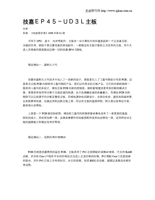
技嘉EP45-UD3L主板作者:来源:《电脑爱好者》2009年第01期不同于CPU、显卡、内存等配件,主板在一台计算机中的位置是起到一个让设备互联、沟通的作用,相较于更注重性能的其他配件,一款稳定的主板才能称之为优秀的主板。
而今天进入评测室的便是稳定压倒一切的技嘉EP45-UD3L稳定理由一、超耐久三代技嘉在超耐久三代技术中加入了一项新的设计,那就是引入了2盎司铜设计内层PCB,这是首次主板PCB内部使用2盎司铜的产品,我们以往常见的主板产品,它们的内部纯铜层一般采用1盎司的来设计。
增加主板PCB内部的纯铜层,据称能够提供更有效的散热解决方案,更高效率地传导分散于主板区域的热源,由于处理器区域的热量最大,而增加PCB内纯铜层可以让热源平均分散至整张主板。
四相电源供电回路设计,全固态电容,超低电阻晶体管以及铁素体电感。
也被应用到这款主板上面,所以在主板的温度控制,耐久度以及寿命方面,都有很大的帮助。
上面是一个PCB板的剖析图,增加到2盎司的纯铜层意味着电流有了一条更宽的通道、阻抗的减少,同时层加厚一倍,这意味着额外的电能损耗和发热也会降低一倍,这同样会对主板的超频能力和稳定性有所帮助。
稳定理由二、成熟的P45+ICH10PCB仍然是技嘉惯用的蓝色PCB,主板采用了P45北桥搭配的ICH10南桥,不支持RAID 功能。
在目前Core i7+X58平台的价格还无法进入主流价格的时候,P45搭配Core 2还是经典的组合。
另外P45已经上市有些时日,对它的挖掘,包括BIOS的功能、超频以及稳定性都非常成熟。
规格芯片组 P45+ICH10CPU种类 Core2 Extreme、Core 2 Quad、Core 2 Duo、PentiumCPU插槽 LGA 775支持内存类型 4×DDR2集成声卡 Realtek ALC888 8声道音效芯片集成网卡 Realtek 8111C千兆网络控制芯片稳定性很好性价比不高单条的PCI-E X16接口以及ICH10南桥,满足了多数用户的实际用途,并进一步降低成本,提高性价比的优势。
技嘉科技 BIOS Flash Version 1.0 用户手册说明书

BIOS FlashVersion 1.0User ManualAdvantech Co. Ltd.No. 1, Alley 20, Lane 26, Rueiguang Road, Neihu District, Taipei 114, Taiwan, R. O. C.BIOS Flash User Manual Copyright NoticeThis document is copyrighted, 2008, by Advantech Co., Ltd. All rights reserved. Advantech Co., Ltd. Reserves the right to make improvements to the products described in this manual at any time. Specifications are thus subject to change without notice.No part of this manual may be reproduced, copied, translated, or transmitted in any form or by any means without prior written permission of Advantech Co., Ltd. Information provided in this manual is intended to be accurate and reliable. However, Advantech Co., Ltd., assumes no responsibility for its use, or for any infringements upon the rights of third parties which may result from its use.All the trade marks of products and companies mentioned in this data sheet belong to their respective owners.Copyright © 1983‐2009 Advantech Co., Ltd. All Rights ReservedBIOS Flash User Manual Version HistoryDate Version Author Description2009/05/01 1.0 CL/Wilson New releaseTable of ContentsIntroduction (4)Product Features (4)Environments (5)System Architecture (5)Support BIOS Type (5)Support OS (5)BIOS Flash Program (6)Installation (6)Main Menu and Control (7)Operation Flow or Procedures (8)SUSI API Programmer’s Documentation (9)[Initialize Module:] (9)(1) bool EPF_InitializeOpen (9)(2) bool EPF_InitializeClose (9)[Information Module:] (10)(3) bool EPF_GetBiosInformation (10)[Flash Module:] (11)(4) EPF_SaveBinFileAsFlashRom (11)[File Module:] (12)(5) EPF_LoadFile2BufAndGetFileCheckSum (12)(6) EPF_LoadProgAndSave2File (12)Appendix (13)A: Supported BIOS Description (13)IntroductionAn embedded system is usually a closed environment, or a headlesssystem tasked with performing one or a few dedicated functions. Whena System Integrator needs to upgrade or update the BIOS, they usuallyneed to turn off the embedded system and go into a DOS environment.However, this is not always so practical and one must be careful when updating the BIOS, usually requiring a technical person to do so—a better way would be to flash the BIOS in a Windows XP environment directly.Now, with Advantech’s BIOS Flash utility, customers can update and backup the BIOS in a Widows XP environment. The BIOS Flash utility allows customers to update the flash ROM BIOS version, or use it to back up current BIOS by copying it from the flash chip to a file on customers’ disk. The BIOS Flash utility also provides a command line version and API for fast implementation into customized applications. Alternatively, customers can add the BIOS Flash function into their embedded applications by calling Advantech BIOS Flash Application Programming Interface (API), or customers can puta new BIOS file on a USB disk so their applications will read it into the BIOSautomatically. With Advantech’s BIOS Flash utility, updates become easier and more integrated.Advantech’s BIOS Flash utility is a tool that allows customers to update and backup the BIOS on Advantech hardware platforms—all in a user friendly interface under Windows XP.Product Featuresz Updates the BIOS version of Flash ROM (Supporting Flash ROM Sizes 1 M, 2 M and 4 M KB)z Backs up your current BIOS by copying it from the flash chip to a file on your disk z Utility and API for fast implementation of custom applicationsz Support Windows XPEnvironmentsSystem ArchitectureX86 systems.Support BIOS TypeFlash Size (1M,2M,4M,16M)KB Flash Type (1M ROM)Support OS1. Windows XP Professional2. Windows XP Embedded3. Windows Embedded StandardBIOS Flash ProgramInstallationBIOS Flash installation is a setup file, please click the setup.exe to do the installation, follow the steps to complete the process. After the installation, this complete utility will include BIOSFlash.exe, ePFlash.dll and ePFlash.sys.Main Menu and ControlOperation Flow or ProceduresGUI Mode:z Backup a BIOS ROM:1. Press Backup Flash ROM button2. Type a file name on save dialog3. Press OKz Update a BIOS ROM:1. Press Flash BIOS ROM button2. Press OK to validate3. Select a binary file open dialog4. Choose the BIOS block which you want to update and confirm it.5. Press OKCommand Modez Backup a BIOS ROM :CBiosFlash.exe –r FileNamez Update a BIOS ROM :CBiosFlash.exe –w FileNamez Update a BIOS ROM by force mode :CBiosFlash.exe –fw FileNameSUSI API Programmer’s DocumentationAll APIs return the BOOL data type except Susi*Available and some special cases that are of type int. If any function call fails, i.e. a BOOL value of FALSE, or an int value of -1, the error code can always be retrieved by an immediate call to SusiGetLastError.[Initialize Module:](1) bool EPF_InitializeOpenbool EPF_InitializeOpen (void* extend_info1)Description: InitializeParameter: extend_info1, [OUT], a reserved parameter, you can set a emptystring.Return: true (1), false (0)(2) bool EPF_InitializeClosebool EPF_InitializeClose ()Description: Un-InitializeParameter: NoneReturn: true (1), false (0)[Information Module:](3) bool EPF_GetBiosInformationbool EPF_GetBiosInformation (char* build_date_buf,char * flash_rom_type_buf,char * flash_rom_id_buf,*bios_ver_buf);charDescription: Get BIOS InformationFlash ROM Type String (such as “SST 49LF004A/B 3.3V”)Onboard chipset name (such as “Grantsdale-6A79DFKGC-00”)Parameter: build_date_buf, [IN], get build date in a buffer.flash_rom_type_buf, [IN], get flash rom type in a buffer.flash_rom_id_buf, [IN], get flash rom id in a buffer.flash_rom_id_buf, [IN], get bios version in a buffer.Return: true (1), false (0)[Flash Module:](4) EPF_SaveBinFileAsFlashRomEPF_SaveBinFileAsFlashRom (HWND hWnd,unsigned int msgID,int flash_area);Description: Update BIOS.Parameter: save_bios_hWnd, [OUT], Show progress windows handle.msgID, [OUT], User defined Windows Message.flash_area, [OUT], Flash Area, 1->boot block, 2->dmi_esce block,4->main block;Message ID: 0x0400 + 0x205Return: true (1), false (0)[File Module:](5) EPF_LoadFile2BufAndGetFileCheckSumEPF_LoadFile2BufAndGetFileCheckSum(char* file_path,unsigned long *file_check_sum);Description: Load BIOS from file to bufferParameter: file_path, [OUT], file pathfile_check_sum, [IN], file check sumReturn: true (1), false (0)(6) EPF_LoadProgAndSave2FileEPF_LoadProgAndSave2File (char* file_path,HWND hWnd,unsigned int msgID);Description: Load BIOS from flash ROM to file.Parameter: file_path, [OUT], file pathload_bios_hWnd, [OUT], Show progress windows handle.msgID, [OUT], User defined Windows Message.Message ID: 0x0400 + 0x204Return: true (1), false (0)AppendixA: Supported BIOS DescriptionFlash Size (1M,2M,4M,16M)KBFlash Type (1M ROM)(AMD, ATMEL, CSI, INTEL, MOSEL, MX_AP, MX_P, SST, AMIC, WIN){AMD_CHIP_ID, "AMD 29F010 /5V "},{ATMEL_CHIP_ID_1, "ATMEL 29C010A /5V "},{ATMEL_CHIP_ID_3, "ATMEL 49F001T /5V "},{CSI_CHIP_ID, "CSI CAT28F001P /12V "},{INTEL_CHIP_ID, "INTEL 28F001BX‐T /12V "},{MOSEL_1M_CHIP_ID, "MOSEL V29C51001T /5V "},{MX_AP_CHIP_ID, "MXIC 28F1000AP /12V "},{MX_P_CHIP_ID, "MXIC 28F1000P /12V "},{MXIC_29F001T_ID, "MXIC 29F001T /5V "},{SST_CHIP_ID, "SST 28EE010 & 28EE011 /5V"},{SST_CHIP_ID_1, "SST 29EE010/5V "},{SST_39SF010_CHIP_ID, "SST 39SF010 /5V "},{AMIC_A29001_ID, "AMIC A29001 /5V "},{WIN_CHIP_ID, "WINBOND 29EE011 /5V "},(AMD, AMIC, ATMEL, BM, CSI, EN, GTK, HY, IMT, INTEL, MOSEL, WINBOND, EFST, WIN, SST, PMC, ST, MXIC, PMC, TI)Flash Type (2M ROM){AMD_2M_CHIP_ID, "AMD 29F002(N)T /5V "},{AMIC_A29002_ID, "AMIC A29002 /5V "},{ATMEL_2M_1_CHIP_ID, "ATMEL 49F002T /5V "},{ATMEL_2M_2_CHIP_ID, "ATMEL 29LV020 /3V "},{ATMEL_2M_CHIP_ID, "ATMEL 29C020 /5V "},{BM_2M_CHIP_ID, "BRIGHT BM29FS020 /5V "},{CSI_2M_CHIP_ID, "CSI CAT28F002T /12V "},{EN_29F002_ID, "EN EN29F002NT /5V "},{GTK_020_CHIP_ID, "ARF35LV020 "},{GTK_022_CHIP_ID, "AVF35LV020 "},{HY_29F002T_ID, "HYUNDAI HY29F002T /5V "},{IMT_2M_CHIP_ID, "IMT IM29F002T /5V "},BIOS Flash User Manual {INTEL_2M_CHIP_ID, "INTEL 28F002BX‐T /12V "},{MOSEL_2M_CHIP_ID, "MOSEL V29C51002T /5V "},{MOSEL_2M_V29LC51002_ID, "MOSEL V29LC51002T /5V”},{WINBOND_49F002T_CHIP_ID, "WINBOND 49F002U /5V "},{WINBOND_39L020_CHIP_ID, "WINBOND 29L020 /3.3V "},{EFST_F49B002UA_CHIP_ID, "EFST F49B002UA /5V "},{WIN_49V002_CHIP_ID, "WINBOND 49V002 /3.3V "},{SST_49LF020_CHIP_ID, "SST 49LF020 LPC /3.3V "},{SST_49LF020A_CHIP_ID, "SST 49LF020A LPC /3.3V "},{PMC_49LP002_Chip_ID, "PMC Pm49LP002 LPC /3.3V "},{PMC_Pm49FL002T_Chip_ID, "PMC Pm49FL002T LPC/FWH”},{ST_M50FW002_ID, "ST M50FW002 FWH "},{ST_M50LPW002_ID, "ST M50LPW002 LPC "},{WIN_49V002F_ID, "WINBOND 49V002F /3.3V "},{ATMEL_AT49LL020_ID, "ATMEL AT49LL020 2Mb LPC "},{SST_49LF003A_CHIP_ID, "SST 49LF003A 3Mb /3.3V "},{SST_49LF030A_CHIP_ID, "SST 49LF030A 3Mb /3.3V "},{MXIC_2000PPC_ID, "MXIC 28F2000PPC /12V "},{MXIC_2000TPC_ID, "MXIC 28F2000TPC /12V "},{MXIC_2M_2_CHIP_ID, "MXIC 28F002TTC /12V "},{MXIC_29F002T_ID, "MXIC 29F002(N)T /5V "},{MXIC_29F022T_ID, "MXIC 29F022(N)T /5V "},{PMC_2M_CHIP_ID, "PMC PM29F002T /5V "},{PMC_39F020_CHIP_ID, "PMC PM39F020 /5V "},{SST_2M_CHIP_ID, "SST 29EE020 /5V "},{SST_2M_1_CHIP_ID, "SST 29LE020 /3V "},{SST_39SF020_CHIP_ID, "SST 39SF020 /5V "},{SST_39VF020_CHIP_ID, "SST 39VF020 /3.3V "},{SST_49LF002_CHIP_ID, "SST 49LF002A /3.3V (2Mb) "},{ST_2M_CHIP_ID, "ST M29F002T /5V "},{TI_2M_CHIP_ID, "INTEL/TI TMS28F020 /12V “},{WINBOND_2M_CHIP_ID, "WINBOND 29C020 /5V "},Flash Type (4M ROM)(AMD, HY, ATMEL, GTK, BM, PMC, BMB, MOSEL, MXIC){AMD_4M_CHIP_ID, "AMD 29F400BT /5V "},{HY_29F040A_ID, "HYUNDAI HY29F040A /5V "},{AMD_16M_CHIP_ID, "AMD 29F160D /5V "},{BMB_16M_CHIP_ID, "MBM 29F160 /5V "},{ATMEL_29C040_ID, "ATMEL 29C040A /5V "},{GTK_040_CHIP_ID, "AVF35LV040 "},{BM_29F040_ID, "BRIGHT BM29FS040 /5V "},{Bright_BM29F040_ID, "BRIGHT BM29F040 /5V "},{PMC_39F040_ID, "PMC PM39F040 /5V "},{PMC_PM29F004T_ID, "PMC Pm29F004T /5V "},{ATMEL_AT49F040T_ID, "ATMEL 49F040T /5V "},{EN_29F040_ID, "EN EN29F040 /5V "},{BMB_29F040_ID, "Fujitsu BMB29F040C /5V "},{MOSEL_29C51004_ID, "MOSEL 29C51004T /5V "},{MXIC_29F004_CHIP_ID, "MXIC 29F004T /5V "},(AMD, HY, ATMEL, GTK, BM, PMC, BMB, MOSEL, MXIC, INTEL, SST, WINBOND, ST, MegaWin, AMIC, IMT){INTEL_E8280AD_ID, "INTEL E82802AB /3.3V(4Mb)"},{INTEL_E82F400B5T_ID, "INTEL E82F400B5 "},{SST_49LF004_CHIP_ID, "SST 49LF004 /3.3V "},{SST_49LF004A_CHIP_ID, "SST 49LF004A/B /3.3V "},{Winbond_FWH_W39V040A_Chip, "Winbond W39V040FA (4Mb)"}, {Winbond_LPC_W39V040AP_Chip, "Winbond W39V040AP (4Mb)"},{PMC_Pm49FL004T_Chip_ID, "PMC Pm49FL004T LPC/FWH"},{ATMEL_AT49LW040_ID, "ATMEL AT49LW040 4Mb FWH"},{ST_M29W040B_ID, "ST M29W040B /3V "},{ST_M29F040B_ID, "ST M29F040B /5V "},{ATMEL_AT49LL040_ID, "ATMEL AT49LL040 4Mb LPC "},{SST_49LF040_CHIP_ID, "SST 49LF040A LPC /3.3V "},{SST_28SF040A_ID, "SST 28SF040A /5V "},{ST_M29F400T_ID, "ST M29F400T /5V "},{WINBOND_29C040_ID, "WINBOND 29C040 /5V "},(AMD, HY, ATMEL, GTK, BM, PMC, BMB, MOSEL, MXIC, INTEL, SST, WINBOND, ST, MegaWin, AMIC, IMT){WINBOND_39L040_CHIP_ID, "WINBOND 29L040 /3.3V "},{MegaWin_MM29F040_ID, "AMD AM29F040B /5V "},{MegaWin_MM29LF040_ID, "MEGAWIN MM29LF040 /3.3V "},{MXIC_MX29F040_ID, "MXIC MX29F040 /5V "},{AMIC_A29040_ID, "AMIC A29040 /5V "},{ST_M50FW040_ID, "ST M50FW040 /3V "},{ST_M50LPW040_ID, "ST M50LPW040 /3V "},{ST_M50LPW041_ID, "ST M50LPW041 /3V "},{SST_39SF040_ID, “SST 39SF040 /5V "},{SST_39SF040P_ID, "SST 39SF040P /5V "},{SST_39VF040P_ID, "SST 39VF040P /5V "},{IMT_4M_CHIP_ID, "IMT IM29F004T /5V "},{INTEL_E8280AC_ID, "INTEL E82802AC /3.3V(8Mb)"},{SST_49LF008_CHIP_ID, "SST 49LF008A /3.3V "},{SST_49LF080A_CHIP_ID, "SST 49LF080A /3.3V "},(AMD, HY, ATMEL, GTK, BM, PMC, BMB, MOSEL, MXIC, INTEL, SST, WINBOND, ST, MegaWin, AMIC, IMT){ST_M50LPW080_ID, "ST M50LPW080 8Mb LPC /3V "},{ST_M50FW080_ID, "ST M50FW080 8Mb FWH /3V "},{ATMEL_AT49LW080_ID, "ATMEL AT49LW080 8Mb FWH "},Flash Type (16M ROM){0x25bf, "SST 25VF016B 16Mb SPI ", SPI}}。