2009款别克昂科雷原厂车身系统喇叭部分维修手册(可编辑)
09款新君威维修手册a16
一般信息漏水1-651.6漏水1.6.1诊断信息和程序1.6.1.1漏水试验准备•上海通用汽车公司的车辆是在正常环境条件下设计运行的。
•密封材料和部件的设计标准考虑了承受自然环境因素所需的密封强度。
但这些规格未能将所有人为条件考虑在内,如高压洗车。
•漏水测试程序与自然环境因素相关,并可确定车辆在正常运行条件下的性能。
•漏水测试的第一步是确定发生泄漏的条件。
如果可以确定大致泄漏部位,则可用通水软管或通气软管隔离确切的进水点。
修理泄漏时,可能需要拆卸某些装饰板或部件。
•如果泄漏出现在车门、车窗、行李厢盖或举升门部位,则不一定是密封条不良造成的。
调整这些部位可能就能解决问题。
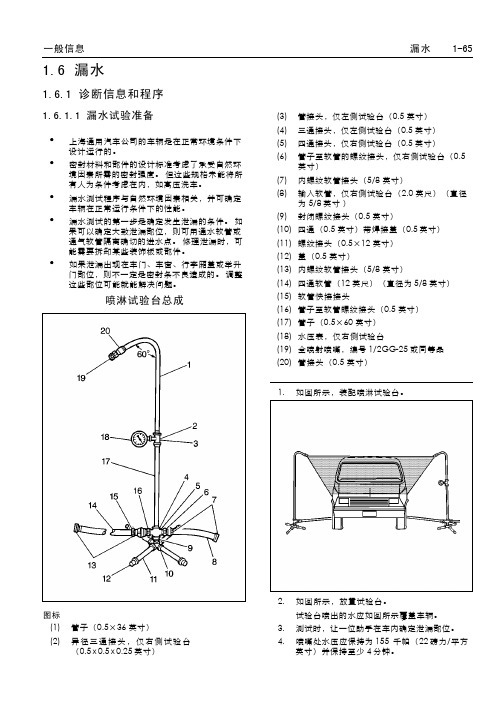
喷淋试验台总成图标(1)管子(0.5×36英寸)(2)异径三通接头,仅右侧试验台(0.5x 0.5x 0.25英寸)(3)管接头,仅左侧试验台(0.5英寸)(4)三通接头,仅左侧试验台(0.5英寸)(5)四通接头,仅右侧试验台(0.5英寸)(6)管子至软管的螺纹接头,仅右侧试验台(0.5英寸)(7)内螺纹软管接头(5/8英寸)(8)输入软管,仅右侧试验台(2.0英尺)(直径为5/8英寸)(9)封闭螺纹接头(0.5英寸)(10)四通(0.5英寸)带焊接盖(0.5英寸)(11)螺纹接头(0.5×12英寸)(12)盖(0.5英寸)(13)内螺纹软管接头(5/8英寸)(14)四通软管(12英尺)(直径为5/8英寸)(15)软管快接接头(16)管子至软管螺纹接头(0.5英寸)(17)管子(0.5×60英寸)(18)水压表,仅右侧试验台(19)全喷射喷嘴,编号1/2GG-25或同等品(20)管接头(0.5英寸)1.如图所示,装配喷淋试验台。
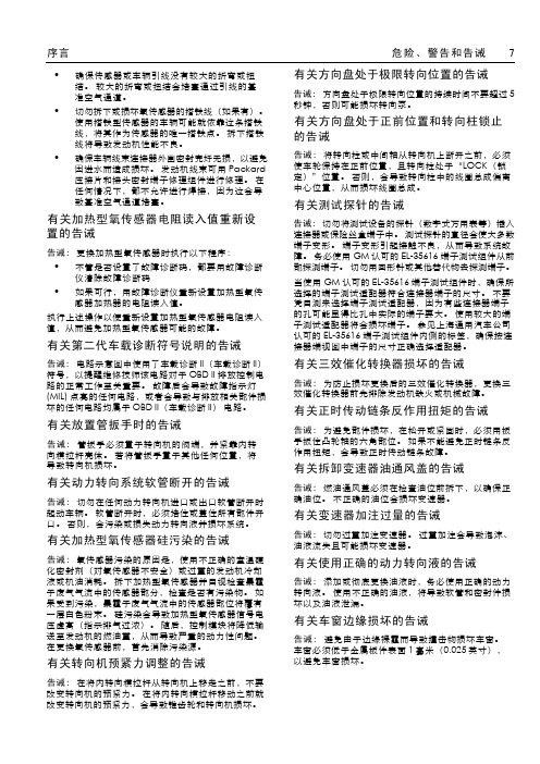
2.如图所示,放置试验台。
试验台喷出的水应如图所示覆盖车辆。
3.测试时,让一位助手在车内确定泄漏部位。
4.喷嘴处水压应保持为155千帕(22磅力/平方英寸)并保持至少4分钟。
湖南万通汽修学校 www.hnwtqx.com1-66漏水一般信息5.检查前风窗玻璃时,应将喷射水流向下偏30度、向后偏45度。
汽车音响故障排除维修手册

汽车音响故障排除维修手册随着汽车科技的不断发展,汽车音响已经成为了车内娱乐的重要设备之一。
然而,由于各种原因,汽车音响也可能会出现故障,影响乘坐者的音乐享受。
本维修手册将为您提供一些常见的汽车音响故障排除方法,帮助您解决问题。
第一步:检查电源连接当您发现汽车音响无法开机或者没有音频输出时,首先需要检查音响的电源连接情况。
请按照以下步骤进行操作:1. 确认音响的电源开关是否打开,如果没有打开,请打开开关。
2. 检查音响的电源线是否与车辆电池连接良好,确保电源线没有断路或者松动。
3. 检查音响电源线的保险丝是否烧毁,如有需要,请更换保险丝。
第二步:检查音频连接如果汽车音响开机正常,但是没有音频输出,您需要检查音频连接是否正确。
请按照以下步骤进行操作:1. 检查音响的音频输入线是否正确连接到音源设备(如手机、MP3等),确保连接牢固。
2. 检查音响的音频输入接口是否有杂音或者损坏,如有需要,请更换音频输入接口。
3. 检查音源设备是否正常工作,您可以尝试连接其他音源设备进行测试,判断是否为音源设备故障造成的问题。
第三步:检查音响设置有时候,汽车音响无法正常工作是因为设置不正确。
请按照以下步骤进行操作:1. 检查音响的音量设置,确保音量适中,不会导致声音过大或者过小。
2. 检查音响的音效设置,确保音效设定正确,不会导致声音失真或者不清晰。
3. 如果您使用了外部功放设备,检查功放设备的连接和设置是否正确。
第四步:专业维修如果您经过以上步骤检查后仍然无法解决汽车音响故障,那么我们建议您寻求专业维修服务。
专业技术人员可以更准确地判断问题所在,并进行维修或更换故障零部件。
注意事项:1. 在进行任何检查或维修操作前,请确保车辆处于安全停止状态,并将电源关闭。
2. 如果您不熟悉音响系统的组成部分和操作原理,请勿自行拆卸或进行复杂的维修操作,以避免进一步损坏设备。
总结:通过这份汽车音响故障排除维修手册,您可以根据故障现象逐步排查问题,并采取相应措施进行修复。
汽车喇叭维修手册

汽车喇叭维修手册在汽车使用中,喇叭是起到提醒、警示以及与其他车辆进行沟通的重要设备。
然而,由于常年使用以及可能的故障,喇叭也会出现一些问题。
本手册旨在提供一些常见汽车喇叭故障的排查方法和维修指南,以帮助车主解决一些简单的问题,提升驾驶安全性和驾乘体验。
第一部分:喇叭故障排查1. 喇叭无声如果你按下喇叭按钮,但喇叭毫无声音,首先需要检查以下几个可能的问题:- 检查喇叭的连接线是否紧固,无松动或腐蚀情况。
- 检查喇叭保险丝是否正常,如需要更换,请使用相同规格的保险丝。
- 检查喇叭继电器是否正常工作,找到喇叭继电器位置并尝试更换一个新的继电器。
2. 喇叭声音异常当喇叭发出不正常的声音,如刺耳、嘶哑或杂音时,可能需要针对不同的问题进行排查和维修:- 检查喇叭的连接线是否损坏或破裂,如有需要及时更换。
- 检查喇叭膜是否有撕裂或变形,如有需要更换整个喇叭部件。
- 检查喇叭所在的位置是否与车辆的结构有冲突,如有可能,重新安放喇叭以避免声音受阻。
- 检查喇叭的电源供应是否稳定,如不稳定可能需要检查发电机或电池的问题。
第二部分:喇叭维护与保养1. 定期清洁定期清洁喇叭可以保持其正常工作和延长使用寿命。
清洁喇叭的步骤如下:- 使用软刷或湿布清除喇叭表面的尘土和污垢。
- 避免使用溶剂或化学清洁剂,以防止对喇叭表面造成损害。
- 清洁后,使用干净的抹布擦拭干燥。
2. 定期检查连接线喇叭的连接线容易受到车辆颠簸以及腐蚀等因素的影响。
因此,定期检查连接线的情况可以有效预防潜在故障发生。
检查时,请注意以下几点:- 检查连接线是否紧固,无松动情况。
- 检查连接线是否有腐蚀现象,清除腐蚀物并保持干燥和清洁。
- 如有需要,可以使用终端润滑剂或防锈液来保护连接线。
3. 防水措施由于汽车喇叭常年暴露在室外环境中,会遇到雨水和湿度等情况。
为了保护喇叭,可以采取以下防水措施:- 安装防水罩或套,防止雨水直接接触到喇叭部件。
- 如发现雨水进入喇叭内部,请尽快清除并保持干燥。
09款新君威维修手册a3
1.2.1 诊断信息和程序 ......................1-29 1.2.1.1 空气/风噪音 ............................................. 1-29 1.2.1.2 示踪粉末或粉笔测试 .................................. 1-29 1.2.1.3 空气压力测试 ........................................... 1-29 1.2.1.4 肥皂泡或气泡测试 ..................................... 1-29
有关方向盘处于正前位置和转向柱锁止 的告诫
告诫: 将转向柱或中间轴从转向机上断开之前,必须 使车轮保持在正前位置,且转向柱处于“LOCK(锁 定)”位置。 否则,会导致转向柱中的线圈总成偏离 中心位置,从而损坏线圈总成。
有关测试探针的告诫
告诫: 切勿将测试设备的探针(数字式万用表等)插入 连接器或保险丝盒端子中。 测试探针的直径会使大多数 端子变形。 端子变形引起接触不良,从而导致系统故 障。 务必使用 GM 认可的 EL-35616 端子测试组件从前 部探测端子。 切勿用回形针或其他替代物去探测端子。 当使用 GM 认可的 EL-35616 端子测试组件时,确保所 选择的端子测试适配器符合连接器端子的尺寸。 不要 凭目测来选择端子测试适配器,因为有些连接器端子 的孔可能显得比孔中实际的端子要大。 使用较大的端 子测试适配器将会损坏端子。 参见上海通用汽车公司 认可的 EL-35616 端子测试组件内侧的标签,确保按连 接器端视图中端子的尺寸正确选择适配器。
有关车窗边缘损坏的告诫
09款新君威维修手册a1
湖南万通汽修学校 www.hnwtqx.com危险危险:为了减少死亡、人身伤害和/或财产损失的可能性,务必认真遵守以下说明:通用汽车有限公司的维修手册,是为合格的专业技术人员使用的。
如果未经适当的培训,没有合适的工具和设备,而试图进行维修或修理,会导致死亡或伤及维修者本人或他人。
还可能损坏车辆或导致车辆不能正常运行。
正确的车辆维护和修理,对于维修技术人员的人身安全和所有机动车辆安全、可靠的操作,均十分重要。
如果需要更换某个零件,请使用相同的零件号或同等零件。
切勿使用劣质的更换零件。
本手册中所推荐和介绍的维修程序是进行维护和修理的有效方法。
其中,有些程序需要使用专为其设计的工具。
因此,如果欲采用未经通用汽车有限公司推荐或认可的更换件、维修程序或工具,必须首先肯定对人身安全或车辆的安全操作没有危害。
本手册包括各种”危险”、”警告”和”告诫”,必须认真遵守,以便在维修或修理中降低人身伤害的风险。
维护或修理不当会损坏车辆,或给车辆带来安全隐患。
这些”危险”、“警告”和“告诫”并不详尽。
上海通用汽车公司不可能对违反这些指示所带来的所有潜在危险后果都作出警告。
本手册包括配备安全气囊车辆的维修程序。
参见“安全气囊系统危险、警告和告诫”中的“警告”。
在安全气囊部件、线路及其周围进行维修前,参见“安全气囊系统”中的安全气囊部件和线路定位图。
不遵循下列这些“危险”、“警告”和“告诫”会引起安全气囊展开、人身伤害或不必要的安全气囊系统修理。
为了避免安全气囊意外展开和人身伤害,如果安全气囊和其他车辆系统都需要修理,建议首先修理安全气囊,然后再修理其他系统。
2009Buick Regal维修手册前言:本维修手册提供了2009Buick Regal诊断、维修程序、调整和规格方面的信息。
技师熟知本手册和相应维修通讯中的资料后,可为用户提供更好的服务。
本手册中提到品牌名称、零件号或专用工具时,维修时可用同等产品替代我们推荐的产品。
别克昂科雷轿车用户手册02
参见本章下文中的 “警告灯”,详细了 解位于组合仪表或车上其他位置的各种 警告灯。
本车还有一个 “驾驶员信息中心”,配 合警告灯和仪表一起工作。 参见本章下 文中的 “驾驶员信息中心”。
1. 远光指示灯
当前照灯设在远光时,指示灯点亮。
2. 转向信号指示灯
转向信号启动时,一个闪烁的箭头 指示转弯或变道方向。
告诫
如果在制动警告灯亮着时驾车,可能 会发生事故。 如果制动警告灯保持点 亮,必须立即检查制动器。
将车辆牵引维修。
防抱死制动系统警告灯
ABS
发动机起动时此灯应短暂点亮,作为一 项检查,表明其工作正常。 如果不亮,应排除故障,使其在发生故 障时能随时发出警告。 如果此灯不熄灭或在行驶过程中启亮, 此系统可能存在故障。 该警告灯点亮的同时,也会发出蜂鸣 声。 尽快停车并关闭发动机。 然后起动发动 机,复位系统。 如果警告灯仍然不熄灭或在车辆行驶过 程中点亮,则需要检修车辆。在排除故 障前,制动器仍能工作,只是没有防抱 死功能。
- 牵引 / 牵引挂车模式按钮 (如 装备)
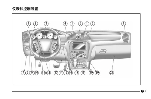
- 电动举升门按钮 - 后窗刮水器 / 清洗器 - 后雾灯开关 18. 附件电源插座 19. 加热型座椅开关 20. 乘客气囊接通 / 关闭指示灯 21. 手套箱
1 -6
组合仪表
82
61
4
2
5
3
7
9
1 -7
图示组合仪表为典型配置。 用户的实际 组合仪表取决于车内的特定选装件。
- 详见本章下文中的 “驾驶员信 息中心”: 行程 / 燃油信息菜单
5. 车速表
车速表的作用是显示车速。
读数可按读数可按公制 (公里 / 小 时)或英制 (英里 / 小时)显示。
别克昂科雷轿车用户手册01

ENCLAVE轿车用户手册感谢您选择了上海通用汽车有限公司的产品,我们将一如既往地保证您驾车愉快,称心如意。
本手册应视作车辆的一个固有部分。
应在出售车辆时随车提供给下一位车主,让其掌握重要的操作、安全和保养信息。
在本车的开发与制造中采用了环保材料和再生材料。
而且,本车的制造方法也是注重环保的。
对生产中产生的废料进行了回收,部分废料经再生后被重新利用。
减少了生产用水,从而保护了自然资源。
本手册所载信息、图示和技术规格均基于印刷时能够获得的最新产品信息。
本公司保留修改产品的权利,恕不事先通知。
手册中采用的图示为典型图,并不真正代表本车任何零件。
请注意,您购买的车辆不一定装备了本手册中介绍的所有配置。
除本《用户手册》外,《保修及保养手册》提供了补充信息。
尽管我们感到这本《用户手册》的内容已经十分全面,已经包括了比较重要的车辆操作说明,但最好还应配合《保修及保养手册》一起使用。
如何使用本手册需要维修时,请谨记上海通用汽车有限公司别克特约售后服务中心最了解您的车辆,能够提供让您满意的服务。
上海通用汽车有限公司别克特约售后服务中心诚邀您在保修期及保修期结束后,将您的维修需求反馈给他们。
如果您对他们的服务不满意,请按照《保修及保养手册》中的步骤向我们反馈。
为了保证您的满意和车辆质量,请确保采用上海通用汽车有限公司原产零件。
上海通用汽车有限公司的零件上标有其商标。
使用该手册了解您的新车功能及其操作方法。
该手册可作为您的参考指南,帮助您快速明确和使用您的车辆的各项功能。
因此,本手册的编排是按功能来安排的,而不是按功能操作来编排的。
手册内还包括了一些非常重要的安全和保养信息以及驾驶时如何排除故障等。
本手册分成5章:z第1章:仪表和控制装置要大致了解本手册的内容编排,想象您正坐在驾驶员的座椅上。
您肯定首先注意到正前方的仪表盘,然后向上向外到后视镜、车窗和车门,然后到后面的行李厢,再到头顶和车顶。
本手册的内容就是按该顺序编排的。
09款新君威维修手册05

2.1外饰2.1.1规格2.1.1.1紧固件紧固规格规格应用公制英制行李厢盖外把手 2.5Y22.1磅力英尺2.1.2维修指南2.1.2.1前后侧车门槛饰板的更换前后侧车门槛饰板的更换引出编号部件名称1前后侧门槛饰板卡夹(数量6)2前后侧车门槛饰板程序断开电气连接器。
2.1.2.2前保险杠蒙皮前牵引孔检修孔盖的更换前保险杠蒙皮前牵引眼检修孔盖的更换引出编号部件名称1前保险杠蒙皮前牵引眼检修孔盖2.1.2.3后保险杠蒙皮后牵引孔检修孔盖的更换后保险杠蒙皮后牵引眼检修孔盖的更换引出编号部件名称1后保险杠蒙皮后牵引眼检修孔盖2.1.2.4后侧门车窗外密封条的更换后侧门车窗外密封条的更换引出编号部件名称1后侧门车窗外密封条卡夹(数量:6)2后侧门车窗外密封条2.1.2.5前侧门车窗框后盖的更换前侧门车窗框后盖的更换引出编号部件名称预备程序1.前门车窗置于全开位置。
2.拆下前侧车门车窗外密封条。
参见前侧门车窗外密封条的更换。
1前侧门车窗框后盖紧固件(数量:3)程序从镶嵌上拉下前侧门车窗密封条,露出紧固件。
2前侧门车窗框后盖2.1.2.6后侧门窗框前盖的更换后侧门车窗框前盖的更换引出编号部件名称预备程序1.后门车窗置于全开位置。
2.拆下后侧车门车窗外密封条。
参见后侧门车窗外密封条的更换。
1后侧门车窗框前盖紧固件(数量:3)程序从镶嵌上拉下后侧门车窗密封条,露出紧固件。
2后侧门车窗框前盖2.1.2.7车身铰链柱填充物的更换车身铰链柱填充物的更换引出编号部件名称1车身铰链柱填充物提示:用BO-569-A插塞提升器释放车身铰链柱填充物。
专用工具BO-569-A插塞提升器2.1.2.8散热器格栅徽标/铭牌的更换散热器格栅徽标/铭牌的更换引出编号部件名称预备程序拆下前保险杠蒙皮以便接近散热器格栅徽标/铭牌总成上的锁紧凸舌。
参见前保险杠蒙皮的更换。
1散热器格栅徽标/铭牌总成提示:松开十五个将散热器格栅徽标/铭牌固定至前保险杠上的前保险杠锁紧凸舌。
- 1、下载文档前请自行甄别文档内容的完整性,平台不提供额外的编辑、内容补充、找答案等附加服务。
- 2、"仅部分预览"的文档,不可在线预览部分如存在完整性等问题,可反馈申请退款(可完整预览的文档不适用该条件!)。
- 3、如文档侵犯您的权益,请联系客服反馈,我们会尽快为您处理(人工客服工作时间:9:00-18:30)。
2009款别克昂科雷原厂车身系统喇叭部分维修手册(可编辑)2009款别克昂科雷原厂车身系统喇叭部分维修手册Horns 4-1Body SystemsHornsSpecicationsSIE-ID 1889233 Owner kyoukh01 LMD 15-mar-2007 LMB amille01Fastener Tightening SpecicationsSpecicationApplicationMetric EnglishCruise Control Switch Bolt 25 N?m 22 lb inHorn Bracket Bolt 9 N?m 80 lb inRadio Control Switch Bolt 25 N?m 22 lb in2009 - Acadia Enclave OUTLOOK Traverse VIN RV Service Manual June 24 20084-2 HornsSchematic and Routing DiagramsSIE-ID 2087799 Owner pluber01 LMD 28-mar-2008 LMB dtrocz012009 - Acadia Enclave OUTLOOK Traverse VIN RV Service Manual June 24 2008Horns 4-3961872scitamehcSnroH2009 - Acadia Enclave OUTLOOK Traverse VIN RV Service Manual June 24 20084-4 HornsDiagnostic Information and ProceduresDiagnostic Starting Point - HornsSIE-ID 1556704 Owner mgastm01 LMD 25-jul-2006 LMB tdedvu01Begin the system diagnosis with the Diagnostic SystemCheck - Vehicle on page 6-60 The Diagnostic SystemCheck will provide the following informationThe identication of the control modules whichcommand the systemThe ability of the control modules to communicatethrough the serial data circuitThe identication of any stored diagnostic troublecodes DTCs and their statusThe use of the Diagnostic System Check will identifythe correct procedure for diagnosing the systemand where the procedure is located2009 - Acadia Enclave OUTLOOK Traverse VIN RV Service Manual June 24 2008Horns 4-5DTC B2750SIE-ID 1873855 Owner tspaul01 LMD 12-jun-2007 LMB tspaul01Diagnostic Instructions DTC DescriptorPerform the Diagnostic System Check - Vehicle DTC B2750 00 Horn Relay Coil Circuiton page 6-60 prior to using this diagnosticprocedureReview Strategy Based Diagnosis on page 6-57 for Diagnostic Fault Informationan overview of the diagnostic approachDiagnostic Procedure Instructions on page 6-58provides an overview of each diagnostic categoryShort to OpenHigh Short to SignalCircuit Ground Resistance Voltage PerformanceHorn Relay B 2 2Horn Relay Control B2750 00 B2750 00 B2750 00Horn Control 2 2 1Horn Switch Ground 2 2Horn Ground 2 21 Horn Always On2 Horn InoperativeCircuitSystem Description Reference InformationThe body control module BCM controls the horn Schematic Reference relay by grounding the control circuit of the horn relaycoil energizing the relay When the horn relay is Horn Schematics on page 4-2energized the horn relay contacts close applyingConnector End View Referencevoltage through the horn fuse and the horn controlcircuit to the horns Component Connector End Views on page 11-211Description and OperationConditions for Running the DTC Horns System Description and Operation on page 4-12When the horn output is actively being requested by Electrical Information Referencethe BCMCircuit Testing on page 11-456Conditions for Setting the DTCConnector Repairs on page 11-478The BCM detects a short to ground open or short to Testing for Intermittent Conditions and Poorvoltage in the horn relay control circuit for Connections on page 11-460approximately 125 milliseconds Wiring Repairs on page 11-465Scan Tool ReferenceAction Taken When the DTC SetsControl Module References on page 6-1 for scan toolThe BCM disables the output to the horn relay until information the next ignition cycleCircuitSystem VericationConditions for Clearing the DTC Command the horns ON and OFF with the scan toolThe DTC clears when the fault is no longer The horns should turn ON and OFF when changingdetected between the commanded statesThe current DTC will become history when therequest for the output is removedThe history DTC will clear after 50 consecutivefault-free ignition cycles have occurred2009 - Acadia Enclave OUTLOOK Traverse VIN RV Service Manual June 24 20084-6 HornsCircuitSystem Testing Symptoms - Horns1 Ignition OFF disconnect the HORN relay SIE-ID 1875165 Ownertspaul01 LMD 01-dec-2006 LMB tdedvu012 Ignition ON verify a test lamp illuminates between Important The following steps must be completedthe B circuit terminal 85 and ground before using the symptom tables If the test lamp does not illuminate test the B 1 Perform Diagnostic System Check - Vehicle oncircuit for a short to ground or an openhigh page 6-60 before using the symptom tables inresistance If the circuit fuse is open test order to verify that all of the following are truethe control circuit terminal 87 for a short toThere are no DTCs setground If all circuits test normal test orreplace the HORN relay The control modules can communicate via theserial data link3 Connect a test lamp between the control circuitterminal 86 and the B circuit terminal 85 2 Review the system operation in order to familiarizeyourself with the system functions Refer to Horns4 Command the horns ON and OFF with a scanSystem Description and Operation on page 4-12tool The test lamp should turn ON and OFFwhen changing between the commanded statesVisualPhysical InspectionIf the test lamp is always OFF test thecontrol circuit for a short to voltage or anInspect for aftermarket devices which could affectopenhigh resistance If the circuit tests normal the operation of the horn system Refer toreplace the BCM Checking Aftermarket Accessories on page 11-455 If the test lamp is always ON test the control Inspect the easily accessible or visible systemcircuit for a short to ground If the circuit tests components for obvious damage or conditionsnormal replace the BCM which could cause the symptom5 If all circuits test normal test or replace the Perform the following if a horn buzzes or has aHORN relay harsh toneInspect for debris in the joint where the hornComponent Testing fastens to the vehicle1 Ignition OFF disconnect the horn relay Test the torque of the horn mountinghardware The horn mounting hardware2 Test for 60–180 ohms between terminals 85should be tightened to a torque ofand 8610 N?m 7 lb ftIf not within the specied range replacethe relayIntermittent3 Test for innite resistance between the followingterminals Faulty electrical connections or wiring may be thecause of intermittent conditions Refer to Testing for30 and 86 Intermittent Conditions and Poor Connections on30 and 87 page 11-46030 and 8585 and 87 Symptom ListIf not the specied value replace the relayRefer to a symptom diagnostic procedure HornsMalfunction on page 4-6 in order to diagnose the4 Install a 30-amp fused jumper wire between relaysymptomterminal 85 and 12 volts Install a jumper wirebetween relay terminal 86 and ground Testfor less than 2 ohms between terminals 30 and 87 Horns Malfunction If greater than the specied range replace SIE-ID 1873856 Owner tspaul01 LMD 28-feb-2008 LMB tspaul01the relayDiagnostic InstructionsRepair Instructions Perform the Diagnostic System Check - Vehicle Perform the Diagnostic Repair Verication on page 6-86 on page 6-60 prior to using this diagnosticafter completing the diagnostic procedure procedureRelay Replacement Attached to Wire Harness Review Strategy Based Diagnosis on page 6-57 foron page 11-521 or Relay Replacement Within an an overview of the diagnostic approachElectrical Center on page 11-522 Diagnostic Procedure Instructions on page 6-58Control Module References on page 6-1 for BCMprovides an overview of each diagnostic categoryreplacement setup and programming2009 - Acadia Enclave OUTLOOK Traverse VIN RV Service Manual June 24 2008Horns 4-7Diagnostic Fault InformationShort to OpenHigh Short to SignalCircuit Ground Resistance Voltage PerformanceHorn Relay B 2 2Horn Relay Control B2750 00 B2750 00 B2750 00Horn Control 2 2 1Horn Switch Ground 2 2Horn Ground 2 21 Horn Always On2 Horn InoperativeCircuitSystem Description CircuitSystem VericationBattery positive voltage is applied at all times to the 1 Ignition ON press and release the steering wheelhorn relay coil and the horn relay switch Pressing the horn pad The horns should sound and emit ahorn switch applies ground through the switch clear and even tone only when the horn padcontacts and the horn relay control circuit to the coil is pressed side of the relay energizing the relay Battery If the horns do not sound when the horn padvoltage is then applied through the switch side of the is pressed or continues sounding after therelay the horn fuse and the horn control circuit to horn pad is released refer to Horn Switchthe horns The body control module BCM may also Circuit Testapply ground to the horn relay control circuit asIf the sound emitted from the horns are notdescribed above The horns sound as long as groundclear and even refer to Horn – Poor Toneis applied to the horn relay control circuit2 Command the Horn ON and OFF with the scanDiagnostic Aids tool The horns should turn ON and OFF whenchanging between the commanded statesIf diagnosing a Horn- Poor Tone condition inspect the If the horns do not turn ON and OFF whenfollowingchanging between the commanded statesDebris or water in the horn assembly refer to Horn Circuit Test Proper horn mounting hardware torque Refer toFastener Tightening Specications on page 4-1 CircuitSystem Testing Debris in the joint where the horns attach to the Horn Switch Circuit Testvehicle1 Ignition OFF disconnect the X2 harness connectorReference Information at the horn switch2 Ignition ON test for less than 1 ohm between theSchematic Reference ground circuit terminal 1 and groundHorn Schematics on page 4-2 If greater than the specied range test theConnector End View Reference ground circuit for an openhigh resistance3 Ignition OFF connect the harness connector atComponent Connector End Views on page 11-211the horn switch and disconnect the HORN relayDescription and Operation 4 Ignition ON verify that a test lamp does Horns System Description and Operation on page 4-12 not illuminate between the control circuitterminal 87 and groundElectrical Information ReferenceIf the test lamp illuminates test the controlCircuit Testing on page 11-456 circuit for a short to voltageConnector Repairs on page 11-478 5 Verify that a test lampilluminates between the BTesting for Intermittent Conditions and Poorcircuit terminal 85 and groundConnections on page 11-460 If the test lamp does not illuminate test the BWiring Repairs on page 11-465 circuit for a short to ground or an openhighresistance If the circuit tests normal andScan Tool Reference the B circuit fuse is open test the controlControl Module References on page 6-1 for scan tool circuit terminal 87 for a short to ground If theinformation circuit tests normal test or replace theHORN relay6 Verify that a test lamp illuminates between the Bcircuit terminal 30 and groundIf the test lamp does not illuminate test the Bcircuit for an openhigh resistance2009 - Acadia Enclave OUTLOOK Traverse VIN RV Service Manual June 24 20084-8 Horns7 Ignition OFF disconnect the harness connector at replace the BCMthe appropriate horn8 Test for less than 5 ohms between the ground Component Testingcircuit terminal A and groundHorn TestIf greater than the specied range test theground circuit for an openhigh resistance 1 Ignition OFF disconnect the harness connector atthe appropriate horn9 Connect the harness connector at theappropriate horn 2 Install a 15A fused jumper wire between thecontrol terminal B and 12 volts Install a jumper10 Ignition ON connect a 15A fused jumper wirewire between the ground terminal A and groundbetween the B circuit terminal 30 and theVerify the horn emits a clear and even tonecontrol circuit terminal 87 Verify the horns areactivatedIf the sound emitted is not clear and evenreplace the hornIf the horns do not activate test the controlcircuit for an openhigh resistance If the Relay Testcircuit tests normal test or replace the horns 1 Ignition OFF disconnect the HORN relay11 Connect a test lamp between the B circuit 2 Test for 60–180 ohms between terminals 85terminal 85 and the control circuit terminal 86and 8612 Press and release the steering wheel horn pad If not within the specied range replaceThe test lamp should turn ON and OFF when the relaychanging between the commanded states3 Test for innite resistance between the followingIf the test lamp is always ON test the control terminalscircuit for a short to ground If the circuit tests30 and 86normal inspect for a sticking horn switch30 and 87If the test lamp is always OFF test the controlcircuit for a short to voltage or an openhigh 30 and 85resistance If the circuit tests normal inspect 85 and 87for an open horn switchIf not the specied value replace the relay13 If all circuits test normal test or replace the4 Install a 30-amp fused jumper wire between relayHORN relayterminal 85 and 12 volts Install a jumper wireHorn – Poor Tone between relay terminal 86 and ground Testfor less than 2 ohms between terminals 30 and 871 Ignition OFF disconnect the harness connector atthe appropriate horn If greater than the specied range replace2 Test for less than 5 ohms between the horn the relayground circuit terminal A and groundIf greater than the specied range test the Repair Instructionsground circuit for a high resistance Perform the Diagnostic Repair Verication on page 6-863 Disconnect the HORN relay after completing the diagnostic procedure4 Test for less than 1 ohm between the controlRelay Replacement Attached to Wire Harnesscircuit terminal 87 and the control circuit on page 11-521 or Relay Replacement Within anterminal B at the horn Electrical Center on page 11-522If greater than the specied range test the Horn Replacement on page 4-9control circuit for an openhigh resistance Steering Wheel Horn Switch Replacement on5 If all circuits test normal test or replace the horn page 4-10Control Module References on page 6-1 for BCMHorn Circuit Testreplacement setup and programming1 Ignition OFF disconnect the HORN relay2 Connect a test lamp between the B circuitterminal 85 and the control circuit terminal 863 Ignition ON command the Horn ON and OFF witha scan tool The test lamp should turn ON andOFF when changing between the commandedstatesIf the test lamp is always ON test the controlcircuit for a short to ground If the circuit testsnormal replace the BCMIf the test lamp is always OFF test circuit thecontrol circuit for a short to voltage or anopenhigh resistance If the circuit tests normal2009 - Acadia Enclave OUTLOOK Traverse VIN RV Service Manual June 24 2008Horns 4-9Repair InstructionsHorn ReplacementSIE-ID 2089581 Owner jbedna01 LMD 01-apr-2008 LMB amille011845510Horn ReplacementCallout Component NamePreliminary ProcedureRemove the front wheelhouse liner front Refer to Front Wheelhouse Front Liner Replacement Traverse on page 3-30 orFront Wheelhouse Front Liner Replacement Outlook on page 3-32Horn BoltCaution Refer to Fastener Caution on page 0-61Tighten9 N?m 80 lb inHornProcedure2Disconnect the electrical connector2009 - Acadia Enclave OUTLOOK Traverse VIN RV Service Manual June 24 20084-10 HornsSteering Wheel Horn Switch ReplacementSIE-ID 2151689 Owner blitch01 LMD 11-jun-2008 LMB dkonop021915485Steering Wheel Horn Switch ReplacementCallout Component NamePreliminary ProcedureRemove the inatable restraint steering wheel module Refer to Inatable Restraint Steering Wheel Module Replacement onpage 13-43Steering Wheel Spoke Cover Qty 21Tip Use gentle pressure to disengage the steering wheel spoke covers from the steering wheelRadio Control Switch Bolt Qty 2Caution Refer to Fastener Caution on page 0-62Tighten25 N?m 22 lb inRadio Control Switch3 ProcedureDisconnect any electrical connectors as neededCruise Control Switch Bolt Qty 24 Tighten25 N?m 22 lb inCruise Control Switch5 ProcedureDisconnect any electrical connectors as needed2009 - Acadia Enclave OUTLOOK Traverse VIN RV Service Manual June 24 2008Horns 4-11Steering Wheel Horn Switch Replacement contdCallout Component NameHorn SwitchProcedure6Disconnect any electrical connectors as neededTip Use gentle pressure to disengage the horn switch from the steering wheel2009 - Acadia Enclave OUTLOOK Traverse VIN RV Service Manual June 24 20084-12 HornsDescription and OperationHorns System Description and Circuit OperationOperation Battery positive voltage is applied at all times to the horn relay coil and the horn relay switch Pressing theSIE-ID 1874499 Owner tspaul01 LMD 20-sep-2007 LMB hbah01 horn switch applies ground to the horn relay controlcircuit When the horn relay control circuit is groundedSystem Description the horn relay is energized and battery positiveThe horn system consists of the following components voltage is applied to the horns through the horn controlHORN fuse circuit The horns sound as long as ground is applied to the horn relay control circuitHorn relayHorn switchHornsBody control module BCMSystem OperationThe vehicle horns are activated whenever thehorn switch is depressedThe BCM commands the horns ON under any ofthe following conditionsWhen the panic button is depressed on theremote control door lock transmitter Forfurther information refer to Keyless EntrySystem Description and Operation WithoutAccessory 2 Way Remote on page 13-17or Keyless Entry System Descriptionand Operation With Accessory 2 WayRemote on page 13-19When the content theft deterrent systemdetects a vehicle intrusion For furtherinformation refer to Content TheftDeterrent CTD Description and Operationon page 13-6When the keyless entry system is used tolock the vehicle a horn chirp may soundto notify the driver that the vehicle has beenlocked The notication feature may beenabled or disabled through personalizationFor further information refer to KeylessEntry System Description and OperationWithout Accessory 2 Way Remote onpage 13-17 or Keyless Entry SystemDescription and Operation With Accessory 2Way Remote on page 13-19When the OnStar system is used to soundthe horns if equipped For further informationrefer to OnStar Description and Operationon page 8-992009 - Acadia Enclave OUTLOOK Traverse VIN RV Service Manual June 24 2008。