XARP-04V-E连接器规格书
xap400安装调试简易手册
理器安装调试简易手册目录 (5)第一章功能概述 (5)特性 (5)专业服务组 (5)产品返回 (6)产品拆封 (6)控制和连接 (7)前面板 (7)后面板 (7)设备互连 (8)扩展总线 (8)操作要求 (9)电源 (9)电话线 (9)设备放置 (10)工作环境 (10)第二章:安装 (10)硬件安装 (10)XAP 的连接 (11)设备互连 (13)扩展总线连接 (13)建立设备互连 (13)设备ID号 (14)分配设备ID号 (14)级联模式 (14)LCD编程 (15)LCD菜单树 (15)调整参数 (16)System主菜单 (17)RS-232主菜单 (18)使用Modem配置XAP 400的步骤 (19)Inputs主菜单 (20)Outputs主菜单 (20)第三章:系统配置 (20)G-Ware的安装要求 (21)创建软盘备份 (21)G-Ware软件的安装 (22)安装G-Ware软件 (22)创建站点 (22)创建一个新的站点 (22)添加XAP 400 (23)G-Ware软件窗口 (26)矩阵窗口 (28)音频路由 (29)O-Z扩展总线路由 (30)A-H音频处理路由 (30)交叉点电平衰减 (30)输入和输出 (32)输入1-4 (32)创建虚拟参考 (35)NLP(非线性处理) (36)Meters(电平表) (36)NC(回声消除器) (36)Filters(滤波器) (37)激活滤波器 (37)滤波器类型 (37)滤波器主要参数 (38)配置滤波器 (39)Gate(门控) (39)麦克激励 (40)Chairman Override(主席模式) (40)Adaptive Ambient(环境自适应模式) (40)PA Adaptive Mode(PA自适应模式) (40)选通率 (41)保持时间 (41)衰减量 (41)环境电平 (41)衰减率 (41)PA自适应和AEC参考 (41)选择门控组(混音器) (42)指定门控组..................................................... 错误!未定义书签。
AV 延长器 AV-E2 AV-E4 AV-E8 说明书

可选购配备
您可以选购以下产品配套使用: 本产品可以提供精确的偏移校准,我们建议当传输距离超过 150 米时,应该用本产品。
(Item No: SK-101)
CAT.5/5E 与 CAT.6 线材的距离和分辨率
50 米
2048x1536
100 米
1280x1024
CAT.5/5E
180 米
1024x768
AV-E-PRO 包装盒内包括 —
1 个本地端 AV-L-PRO 1 个远端 AV-R-PRO 1 本用户手册 2 个 DC 12V/600mA 电源 1 条 1.2 米长的 VGA 线材(HD-15 公头对公头) 1 条 1.2 米音频线材
AV-E2 包装盒内包括 —
1 个本地端 AV-E2 1 本用户手册 1 个 DC 12V/600mA 电源 2 条支架,6 个螺丝 1 条 1.2 米长的 VGA 线材(HD-15 公头对公头) 1 条 1.2 米音频线材
AV-E16 包装盒内包括 —
1 个本地端 AV-E16 1 本用户手册 2 条支架,6 个螺丝 1 条电源线 1 条 1.2 米长的 VGA 线材(HD-15 公头对公头) 1 条 1.2 米音频线材
AV-E32 包装盒内包括 —
1 个本地端 AV-E32 1 本用户手册 2 条支架,6 个螺丝 1 条电源线 1 条 1.2 米长的 VGA 线材(HD-15 公头对公头) 1 条 1.2 米音频线材
AV-E2 AV-E4 AV- E8 AV-E16
AV-E32
1x HD-15 母头接口
1x HD-15 母头接口
1x 3.5ψ立体声接口
1x 3.5ψ立体声接口
欧洲品牌电磁器件型号123456产品说明书
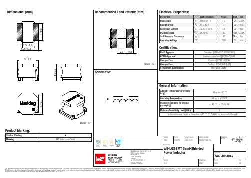
Dimensions: [mm]Scale - 5:174404054047BC74404054047T e m p e r a t u r eT pT L74404054047Cautions and Warnings:The following conditions apply to all goods within the product series of WE-LQS of Würth Elektronik eiSos GmbH & Co. KG:General:•This electronic component is designed and manufactured for use in general electronic equipment.•Würth Elektronik must be asked for written approval (following the PPAP procedure) before incorporating the components into any equipment in fields such as military, aerospace, aviation, nuclear control, submarine, transportation (automotive control, train control, ship control), transportation signal, disaster prevention, medical, public information network etc. where higher safety and reliability are especially required and/or if there is the possibility of direct damage or human injury.•Electronic components that will be used in safety-critical or high-reliability applications, should be pre-evaluated by the customer. •The component is designed and manufactured to be used within the datasheet specified values. If the usage and operation conditions specified in the datasheet are not met, the wire insulation may be damaged or dissolved.•Do not drop or impact the components, the component may be damaged.•Würth Elektronik products are qualified according to international standards, which are listed in each product reliability report. Würth Elektronik does not warrant any customer qualified product characteristics beyond Würth Elektroniks’ specifications, for its validity and sustainability over time.•The responsibility for the applicability of the customer specific products and use in a particular customer design is always within the authority of the customer. All technical specifications for standard products also apply to customer specific products.Product specific:Soldering:•The solder profile must comply with the technical product specifications. All other profiles will void the warranty.•All other soldering methods are at the customers’ own risk.•Strong forces which may affect the coplanarity of the components’ electrical connection with the PCB (i.e. pins), can damage the part, resulting in avoid of the warranty.Cleaning and Washing:•Washing agents used during the production to clean the customer application might damage or change the characteristics of the wire insulation, marking or plating. Washing agents may have a negative effect on the long-term functionality of the product.•Using a brush during the cleaning process may break the wire due to its small diameter. Therefore, we do not recommend using a brush during the PCB cleaning process.Potting:•If the product is potted in the customer application, the potting material may shrink or expand during and after hardening. Shrinking could lead to an incomplete seal, allowing contaminants into the core. Expansion could damage the components. We recommend a manual inspection after potting to avoid these effects.Storage Conditions:• A storage of Würth Elektronik products for longer than 12 months is not recommended. Within other effects, the terminals may suffer degradation, resulting in bad solderability. Therefore, all products shall be used within the period of 12 months based on the day of shipment.•Do not expose the components to direct sunlight.•The storage conditions in the original packaging are defined according to DIN EN 61760-2.•The storage conditions stated in the original packaging apply to the storage time and not to the transportation time of the components. Packaging:•The packaging specifications apply only to purchase orders comprising whole packaging units. If the ordered quantity exceeds or is lower than the specified packaging unit, packaging in accordance with the packaging specifications cannot be ensured. Handling:•Violation of the technical product specifications such as exceeding the nominal rated current will void the warranty.•Applying currents with audio-frequency signals may result in audible noise due to the magnetostrictive material properties.•The temperature rise of the component must be taken into consideration. The operating temperature is comprised of ambient temperature and temperature rise of the component.The operating temperature of the component shall not exceed the maximum temperature specified.These cautions and warnings comply with the state of the scientific and technical knowledge and are believed to be accurate and reliable.However, no responsibility is assumed for inaccuracies or incompleteness.Würth Elektronik eiSos GmbH & Co. KGEMC & Inductive SolutionsMax-Eyth-Str. 174638 WaldenburgGermanyCHECKED REVISION DATE (YYYY-MM-DD)GENERAL TOLERANCE PROJECTIONMETHODChrB.001.0062022-10-01DIN ISO 2768-1mDESCRIPTIONWE-LQS SMT Semi-ShieldedPower Inductor ORDER CODE74404054047SIZE/TYPE BUSINESS UNIT STATUS PAGEImportant NotesThe following conditions apply to all goods within the product range of Würth Elektronik eiSos GmbH & Co. KG:1. General Customer ResponsibilitySome goods within the product range of Würth Elektronik eiSos GmbH & Co. KG contain statements regarding general suitability for certain application areas. These statements about suitability are based on our knowledge and experience of typical requirements concerning the areas, serve as general guidance and cannot be estimated as binding statements about the suitability for a customer application. The responsibility for the applicability and use in a particular customer design is always solely within the authority of the customer. Due to this fact it is up to the customer to evaluate, where appropriate to investigate and decide whether the device with the specific product characteristics described in the product specification is valid and suitable for the respective customer application or not.2. Customer Responsibility related to Specific, in particular Safety-Relevant ApplicationsIt has to be clearly pointed out that the possibility of a malfunction of electronic components or failure before the end of the usual lifetime cannot be completely eliminated in the current state of the art, even if the products are operated within the range of the specifications.In certain customer applications requiring a very high level of safety and especially in customer applications in which the malfunction or failure of an electronic component could endanger human life or health it must be ensured by most advanced technological aid of suitable design of the customer application that no injury or damage is caused to third parties in the event of malfunction or failure of an electronic component. Therefore, customer is cautioned to verify that data sheets are current before placing orders. The current data sheets can be downloaded at .3. Best Care and AttentionAny product-specific notes, cautions and warnings must be strictly observed. Any disregard will result in the loss of warranty.4. Customer Support for Product SpecificationsSome products within the product range may contain substances which are subject to restrictions in certain jurisdictions in order to serve specific technical requirements. Necessary information is available on request. In this case the field sales engineer or the internal sales person in charge should be contacted who will be happy to support in this matter.5. Product R&DDue to constant product improvement product specifications may change from time to time. As a standard reporting procedure of the Product Change Notification (PCN) according to the JEDEC-Standard inform about minor and major changes. In case of further queries regarding the PCN, the field sales engineer or the internal sales person in charge should be contacted. The basic responsibility of the customer as per Section 1 and 2 remains unaffected.6. Product Life CycleDue to technical progress and economical evaluation we also reserve the right to discontinue production and delivery of products. As a standard reporting procedure of the Product Termination Notification (PTN) according to the JEDEC-Standard we will inform at an early stage about inevitable product discontinuance. According to this we cannot guarantee that all products within our product range will always be available. Therefore it needs to be verified with the field sales engineer or the internal sales person in charge about the current product availability expectancy before or when the product for application design-in disposal is considered. The approach named above does not apply in the case of individual agreements deviating from the foregoing for customer-specific products.7. Property RightsAll the rights for contractual products produced by Würth Elektronik eiSos GmbH & Co. KG on the basis of ideas, development contracts as well as models or templates that are subject to copyright, patent or commercial protection supplied to the customer will remain with Würth Elektronik eiSos GmbH & Co. KG. Würth Elektronik eiSos GmbH & Co. KG does not warrant or represent that any license, either expressed or implied, is granted under any patent right, copyright, mask work right, or other intellectual property right relating to any combination, application, or process in which Würth Elektronik eiSos GmbH & Co. KG components or services are used.8. General Terms and ConditionsUnless otherwise agreed in individual contracts, all orders are subject to the current version of the “General Terms and Conditions of Würth Elektronik eiSos Group”, last version available at .Würth Elektronik eiSos GmbH & Co. KGEMC & Inductive SolutionsMax-Eyth-Str. 174638 WaldenburgGermanyCHECKED REVISION DATE (YYYY-MM-DD)GENERAL TOLERANCE PROJECTIONMETHODChrB.001.0062022-10-01DIN ISO 2768-1mDESCRIPTIONWE-LQS SMT Semi-ShieldedPower Inductor ORDER CODE74404054047SIZE/TYPE BUSINESS UNIT STATUS PAGE。
ESA 认证的微型连接器说明书
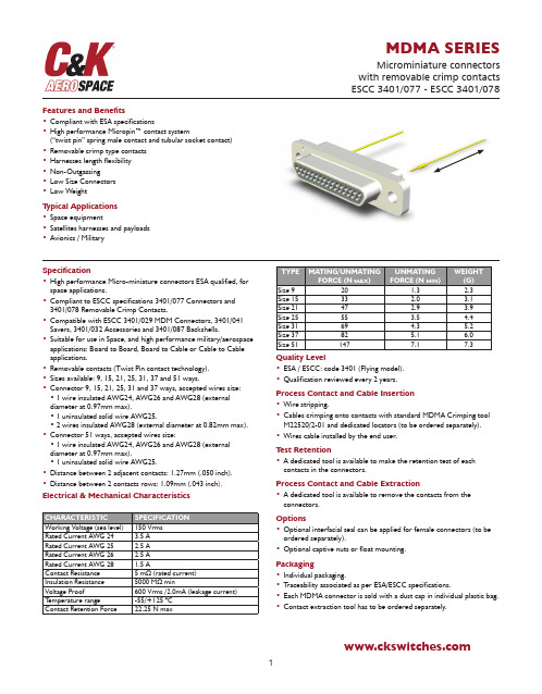
MDMA SERIESMicrominiature connectors with removable crimp contacts ESCC 3401/077 - ESCC 3401/078Features and Benefits•Compliant with ESA specifications•High performance Micropin™ contact system(“twist pin” spring male contact and tubular socket contact)•Removable crimp type contacts •Harnesses length flexibility •Non-Outgassing•Low Size Connectors •Low WeightT ypical Applications•Space equipment•Satellites harnesses and payloads •Avionics / MilitarySpecification•High performance Micro-miniature connectors ESA qualified, for space applications.•Compliant to ESCC specifications 3401/077 Connectors and 3401/078 Removable Crimp Contacts.•Compatible with ESCC 3401/029 MDM Connectors, 3401/041Savers, 3401/032 Accessories and 3401/087 Backshells.•Suitable for use in Space, and high performance military/aerospace applications: Board to Board, Board to Cable or Cable to Cable applications.Quality Level•ESA / ESCC: code 3401 (Flying model).•Qualification reviewed every 2 years.Process Contact and Cable Insertion•Wire stripping.•Cables crimping onto contacts with standard MDMA Crimping tool M22520/2-01 and dedicated locators (to be ordered separately).•Wires cable installed by the end user.T est Retention•A dedicated tool is available to make the retention test of each contacts in the connectors.Process Contact and Cable Extraction•A dedicated tool is available to remove the contacts from the connectors.Options•Optional interfacial seal can be applied for female connectors (to be ordered separately).•Optional captive nuts or float mounting.Packaging•Individual packaging.•T raceability associated as per ESA/ESCC specifications.•Each MDMA connector is sold with a dust cap in individual plastic bag.•Contact extraction tool has to be ordered separately.•Removable contacts (Twist Pin contact technology).•Sizes available: 9, 15, 21, 25, 31, 37 and 51 ways.•Connector 9, 15, 21, 25, 31 and 37 ways, accepted wires size:•1 wire insulated AWG24, AWG26 and AWG28 (external diameter at 0.97mm max).•1 uninsulated solid wire AWG25.•2 wires insulated AWG28 (external diameter at 0.82mm max).•Connector 51 ways, accepted wires size:•1 wire insulated AWG24, AWG26 and AWG28 (external diameter at 0.97mm max).•1 uninsulated solid wire AWG25.•Distance between 2 adjacent contacts: 1.27mm (.050 inch).•Distance between 2 contacts rows: 1.09mm (.043 inch ).Electrical & Mechanical CharacteristicsOur easy build-a-connector concept allows you to mix and match options to create the MDMA you need. T o order, select desired option from each category and place it in the appropriate box.CONNECTOR340107701B MDMA Y 9P -FOShell Finish 01 25.4 µm Ni02 0.7 µm Au over 25.4 µm Ni T ype of Contact P Pin (Male)S Socket (Female)Detail Specification Number Contacts InformationFO Connector without contacts(Contacts must be ordered separately)Fixing OptionNothing: Standard (no hardware)E Captive nut Y Float mountT esting Level Shell Size 9 15 21 25 31 37 51MDMA SeriesPin connection with Nickel Plating Pin connection with Gold PlatingESA/ESCC Specification:ATTACHMENT OPTIONSCaptive Nut (Option E)Floating Mount (Option Y)CONTACT SOCKET – 340107804B (WIRE SIZE AWG 24, 25, 26, 28 OR 2X28)C&K Part Number: C331-8754-000H ESA/ESCC Description:340107803BC&K Part Number: C252-8844-000H ESA/ESCC Description:340107804BNota:Other products available:-Male Contact 340107801B, compatible with wire size AWG 25, 26 or 28.-Female Contact 340107802B, compatible with wire size AWG 25, 26, 28.Cable Crimping1 – Insert wire into contact body.2 – Insert the unit into the crimping tool (selector position 2) with dedicated locator.Crimping tool - Position #2:M22520/2-01 (P/N: C995-0001-584)Contact InsertionInsert contact with wire into rear insulator cavity until positive stop.T o avoid stress onto retention clip, insert contact in the axis (no insertion angle).T o be sure contact is locked securely, pull back lightly on wire or use calibrated test retention tool.MDMA-Retention tool (P/N: C115373-0003).1 – Select contact extraction tool:- Connector size 9 to 37 ->MDMA-Extract tool-01 (P/N: C115373-0006)- Connector size 51 ->MDMA-Extract tool-02 (P/N: C115373-0007)2 – Insert tool tip into contact cavity until tip bottoms against contact shoulder, releasing tine.Hold wire against tool with finger and remove tool and contact.Be careful to put extraction tool in the good position!Each contact cavity has flat area to place tool tip.Connector size 9 to 37Connector size 51Locator for Male Contact:MDMA-Locator-P-01 (P/N: C115373-0001) Locator for Female Contact:MDMA-Locator-S -01(P/N: C115373-0002)Insert the tip of the tool around the Pin contactPush the tool up to the stop with the front face of the connector Pull back lightly on wire to be sure contact is locked securelyUse Retention Test Tool - P/N C115373-0003This tool is equipped with 2 test tips at the ends for use with Pin and Socket connectors .It is delivered with:• 2 protective caps• 1 adaptator for connectors MDMA-51S1 calibration certificate referring to applicable force and travel If necessary, we can perform the calibration of tools already in service. Use P/N C115373-0003 CA for a quote .MDMA Connector with Pin Contacts:MDMA Connector with Socket Contacts:Insert the tip of the tool inside the Socket contactPush the tool up to the stop with the front face of the connectorPull back lightly on wire to be sure contact is locked securelyMALE SCREWLOCKCRIMPING TOOLLOCATOREXTRACTION TOOLTEST RETENTION TOOLFor the complete range of accessories and details, consult our MDM accessories datasheet.ASIAT el: +852.3713.5288EUROPET el: +33.1.60.24.51.51AMERICAS T el: +1.617.969.3700CONTACTS DESCRIPTION AND C&K PART NUMBERS*T o be preferred. Designed for all wires combination.。
专业I-PEX4微型射频同轴连接器

①
TOOL
② Packing
0 1 R
for Hand Tool ( with Notch ) for Semi-Auto ( without Notch ) Reel 1reel : 2,000pcs
【Applicable Cable Size】
Part No. (Au) Part No. (Ag)
◆All Center contact are Gold Plated I-PEX Co.,Ltd.
1
Easy and Speedy Cable Connection of Center Conductor ( i-Fit ) and Outer Conductor at Only one operation by our special assembling tool
Dielectric Core
(7/0.05) φ0.15
(φ0.85)
(φ0.65)
Nominal
Nominal
Nominal
Nominal
Braided Shield of Outer Conductor
Nominal
Single Braided Shield
Single Braided Shield
2.1
Housing
Sect.A-A
Contact
【Material and Finish】
Parts
HOUSING CONTACT GROUND CONTACT
Material
LCP UL94V-0 COPPER ALLOY COPPER ALLOY
Plating / Color (3pads)
NATURAL Au Au or Ag
TE泰科高压直流接触器全系列型号详细介绍

EV200AD---
EV200AJ-- -
EV200HA---
EV200HD---
EV200HJ---
EV250-1A
EV250-1B
EV250-2A
EV250-2B
EV250-5A
EV500-4A
EV500-4B
EV500-5A
EV500-5B
K61A- --
K61B---
K61C---
Voltage Max.
15VDC
30VDC
60VDC
36VDC
95VDC
95VDC
——
——
——
最大拾起电压
Pickup(close)
voltage Max.
9.6VDC
19.2VDC
38.4VDC
9VDC
32VDC
48VDC
-1A/B: 8.3/ 16.6VDC
-2A/B:9/ 18VDC
-5A:9VDC
9.9VDC
19.7VDC
8VDC
16VDC
80VDC
安装方式
Mounting Terminals
底部/侧面
Bottom/ Side
底部
Bottom
PC板
PC Board
连接方式
Terminal Options
螺栓/ 引出线
Male 10mm×M8 Threaded Terminals/ Wires
-55℃~ +85℃
标称重量(kg)
Weight, Typical
0.60
0.43
0.7 kg / 0.8 kg
1.53kg
——
XG4平面电缆连接器:主流电路板连接器,符合MIL标准,设计得更加优秀说明书

1XG4Flat Cable ConnectorsThe Mainstream of Circuit BoardConnectors conforming MIL Standards with Improved Design.■Our new production system improves reliability.■Space-saving Box-type Plugs (XG4C) available.■IDC Plugs (XG4E) can be used for relaying.■An endless number of combinations can be madeusing the XG-5 IDC Connectors for discrete wires,XG8 Original Plugs, and the XG2 IDC Connectors for PCBs.■The Original Plugs (XG8) and the Box-type Plugs (XG4C) can be locked using Lock Levers.■Conform to MIL standards (MIL-C-83503).■UL standards (file No. E103202) (All XG4 models except those with XG4U and XG4H)■Terminologyz MIL standardAbbreviation for Military Standard. To unify the compatibil-ity and quality assurance condition of each company, MIL-C-83503 (applicable to connectors) was established in 1977.z Open-end coverAn open-end cover has a structure where a flat cable can be pulled out from both sides of the cover when a cable is attached to a connector. (The cover having a structure where a flat cable can be pulled out from only one side of the cover is called a "Closed-end cover.")z StandoffPart provided for lifting the housing from the board (This part improves airflow at the through-hole for better assem-bly.)■Ordering InformationRoHS CompliantItemMIL Sockets: XG4M Relay Plug: XG4EMIL Plugs: XG4A Box-type Plugs: XG4CPCB-to-PCB Connectors: XG4HRated current 1 A 3 A (See note 1.)Rated voltage250 VAC 300 VAC Contact resistance 20 m Ω max. (at 20 mV, 100 mA max.)Insulation resistance 1,000 M Ω min. (at 500 VDC)Dielectric strength 500 VAC for 1 min (leakage current: 1 mA max.)Note:1.The rated current will depend on theSocket you are using. It is 1 A using the XG4M for example.Total insertion force 1.96 N max. per contactRemoval force 0.39 N min. (with test gauge, t= 0.64 mm)Insertion durability 50 timesAmbient operating temperatureOperating: −55 to 105°C (with no icing )of Terminal2Flat Cable Connectors XG4■Materials and Finish■Applicable WiresFor pressing1.27-mm pitch flat cable incorporating AWG28 wires•UL2651(standard cable)•UL20012 (folding cable)•UL20028 (color-coded cable)■Mating Combinations for XG4 and XG5ItemMIL Plugs: XG4A Box-type Plugs: XG4C Relay Plugs: XG4E (Strain Relief: XG4S)MIL Sockets: XG4M (Strain Relief: XG4T)Board-to-boardConnector: XG4H Housings Fiber-glass reinforced PBT resin (UL94V-0)/black Covers ---Polyamide resin (UL94V-0)/black Fiber-glass reinforced PBTresin (UL94V-0)/black---Contacts Mating end Brass/nickel base, 0.15-µm gold platingPhosphor bronze/nickel base, 0.15-µm gold platingTerminal Press fit Brass/nickel base, 2.0-µm tin platingPhosphor bronze/nickel base, 2.0-µm tin platingStrain Reliefs ---Polyamide resin (UL94V-0)/black Fiber-glass reinforced PBTresin (UL94V-0)/black---XG4M-U MIL Connectors with Socket Locks■Dimensions(Unit: mm)■Ordering InformationNote:1.With open-end cover.2.Strain Relief sold separately.3.Polarity guide pitch is 22.86 mm.XG4UXG4M-XG4M-■Mating Diagrams for XG4MFlat Cable Connectors XG434Flat Cable Connectors XG4XG4M MIL Sockets■Dimensions(Unit: mm)XG4M-@@30-T (XG4M-@@30 + XG4T-@@04)XG4M-@@31-T (XG4M-@@31 + XG4T-@@04)MIL Socket and Strain Relief Sets■Ordering InformationNote:1.With open-end cover.2.Strain Relief sold separately.3.Polarity guide pitch is 22.86 mmStrain reliefOpen-end coverTriangular markPolarizing Key slot (2) (Not on models with less than 14 contacts.)Polarity guide Polarizing Key slot (1)XG4M-@@30 (one polarizing guide)XG4M-@@31 (all others)XG4T-@@04Strain ReliefDimensionsNo. of contactsDimensions (mm)A B 1017.310.161422.315.241624.917.782030.022.862637.630.483042.735.563447.740.644055.448.265068.160.966080.873.666485.878.74No. of contactsNo. of polarity guidesSocket and Strain Relief Set (See note 1.)Socket with Open-end Cover (See note 2.)Strain Relief for the XG4M100XG4M-1031-T XG4M-1031XG4T -10041XG4M-1030-T XG4M-1030141XG4M-1430-T XG4M-1430XG4T -1404161XG4M-1630-T XG4M-1630XG4T -1604201XG4M-2030-T XG4M-2030XG4T -2004261XG4M-2630-T XG4M-2630XG4T -2604301XG4M-3030-T XG4M-3030XG4T -3004341XG4M-3430-T XG4M-3430XG4T -3404401XG4M-4030-T XG4M-4030XG4T -4004501XG4M-5030-T XG4M-5030XG4T -50042 (See note 3.)XG4M-5031-T XG4M-5031601XG4M-6030-T XG4M-6030XG4T -60042 (See note 3.)XG4M-6031-T XG4M-6031641XG4M-6430-TXG4M-6430XG4T -64042 (See note 3.)XG4M-6431-TXG4M-6431Flat Cable Connectors XG45XG4A MIL Plugs with Long Locks (MIL Standards)■Dimensions(Unit: mm)Straight DIP terminals Right-angle DIP terminals0.635 × 0.6350.635 × 0.635Straight DIP terminals Right-angle DIP terminalsTwo, 2.6 dia.(M3 tapping screw hole)Two, 2.65 dia.Triangular markPolarizing Key slot (not on models with less than 14 contacts)Polarity slotPolarizing Key slotMounting view (bottom view)Right-angle terminals 0.8 dia. (DIP terminals)0Two, 2.8 dia. (M2.6)Two, 3.2 dia. (M3 tapping screw hole)Straight terminals0.8 dia. (DIP terminals)0Two, 3.2 dia.(M3 tapping screw hole)XG4A-@@31/-@@71 (With straight DIP terminals)XG4A-@@34/-@@74 (With right-angle DIP terminals)DimensionsNote:See page 16 for details on the availability (10-contact Connectors)and pitch (with 50, 60, or 64-contact Connectors) of polarity slot s.No. of contacts Dimensions (mm)A B C D E F 1032.017.510.1621.827.946.41437.122.615.2426.933.051.51639.625.217.7829.535.654.12044.730.222.8634.540.659.12652.337.930.4842.248.366.83057.442.935.5647.253.371.83462.548.040.6452.358.476.94070.155.648.2659.966.084.55082.868.360.9672.678.797.26095.581.073.6685.391.4109.964100.686.178.7490.496.5115.06Flat Cable Connectors XG4■Ordering InformationUse in Combination with Strain-relief Sockets.Note:Polarizing slot pitch is 22.86 mm.No. ofcontactsNo. of polarizing slotsPlugs with straight DIP terminalsPlugs with right-angle DIP terminals100XG4A-1071XG4A-10741XG4A-1031XG4A-1034141XG4A-1431XG4A-1434161XG4A-1631XG4A-1634201XG4A-2031XG4A-2034261XG4A-2631XG4A-2634301XG4A-3031XG4A-3034341XG4A-3431XG4A-3434401XG4A-4031XG4A-4034501XG4A-5031XG4A-50342 (See note.)XG4A-5071XG4A-5074601XG4A-6031XG4A-60342 (See note.)XG4A-6071XG4A-6074641XG4A-6431XG4A-64342 (See note.)XG4A-6471XG4A-6474Flat Cable Connectors XG47XG4A MIL Plugs with Short Locks■Dimensions(Unit: mm)Straight DIP terminals Right-angle DIP terminals0.635 × 0.6350.635 × 0.635Straight DIP terminals Right-angle DIP terminalsMounting holes (bottom view)Right-angle terminalsStraight terminalsTwo, 2.6 dia.(M3 tapping screw hole)Two, 2.65 dia.Polarizing Key slot (not on models with less than 14 contacts)Triangular markPolarity slotPolarizing Key slot0.8 dia. (DIP terminals)00.8 dia. (DIP terminals)Two, 2.8 dia. (M2.6)Two, 3.2 dia. (M3 tapping screw hole)Two, 3.2 dia. (M3 tapping screw hole)XG4A-@@32/-@@72 (With straight DIP terminals)XG4A-@@35/-@@75 (With right-angle DIP terminals)DimensionsNote:See page 16 for details on the availability (10-contact Connectors)and pitch (with 50, 60, or 64-contact Connectors) of polarity slot s.No. ofcontacts Dimensions (mm)A B C D E F 1032.017.510.1621.827.940.41437.122.615.2426.933.045.51639.625.217.7829.535.648.02044.730.222.8634.540.653.12652.337.930.4842.248.360.73057.442.935.5647.253.365.83462.548.040.6452.358.470.94070.155.648.2659.966.078.55082.868.360.9672.678.791.26095.581.073.6685.391.4103.964100.686.178.7490.496.5109.08Flat Cable Connectors XG4■Ordering InformationUse in combination with sockets without strain-relief.Note:Polarizing slot pitch is 22.86 mm.No. ofcontactsNo. of polarizing slotsPlugs with straight DIP terminalsPlugs with right-angle DIP terminals100XG4A-1072XG4A-10751XG4A-1032XG4A-1035141XG4A-1432XG4A-1435161XG4A-1632XG4A-1635201XG4A-2032XG4A-2035261XG4A-2632XG4A-2635301XG4A-3032XG4A-3035341XG4A-3432XG4A-3435401XG4A-4032XG4A-4035501XG4A-5032XG4A-50352 (See note.)XG4A-5072XG4A-5075601XG4A-6032XG4A-60352 (See note.)XG4A-6072XG4A-6075641XG4A-6432XG4A-64352 (See note.)XG4A-6472XG4A-6475Flat Cable Connectors XG49XG4A MIL Plugs without Lock Levers (Lock Leversmounted later)■Dimensions(Unit: mm)Straight DIP terminals Right-angle DIP terminals0.635 × 0.6350.635 × 0.635Straight DIP terminals Right-angle DIP terminalsT wo, 2.6 dia.(M3 tapping screw hole)Two, 2.65 dia.Polarizing Key slot (not on models with less than 14 contacts)Polarity slotPolarizing Key slotTriangular markMounting holes (bottom view)Right-angle terminalsStraight terminals0.8 dia. (DIP terminals)00.8 dia. (DIP terminals)0T wo, 2.8 dia. (M2.6)T wo, 3.2 dia. (M3 tapping screw hole)T wo, 3.2 dia.(M3 tapping screw hole)C ±0.12D ±0.15XG4A-@@33/-@@73 (With straight DIP terminals)XG4A-@@36/-@@76 (With right-angle DIP terminals)DimensionsNote:See page 16 for details on the availability (10-contact Connectors)and pitch (with 50, 60, or 64-contact Connectors) of polarizing slot s.No. of contacts Dimensions (mm)A B C D E 1032.017.510.1621.827.91437.122.615.2426.933.01639.625.217.7829.535.62044.730.222.8634.540.62652.337.930.4842.248.33057.442.935.5647.253.33462.548.040.6452.358.44070.155.648.2659.966.05082.868.360.9672.678.76095.581.073.6685.391.464100.686.178.7490.496.510Flat Cable Connectors XG4■Ordering InformationNote:Polarity slot pitch is 22.86 mm.Lock Levers•This series of Connectors allows you to attach Lock Levers on Right-angle Terminal Plugs after automated soldering is completed.•Lock Levers can be easily mounted simply by manually pushing them in.Note:The left and right Lock Levers are identical. One pair is neededfor each Plug.Attachment after Soldering•Long Levers interfere with automated mounting.•Long Levers are in the way when boards are packed.↓•These problems are resolved using Connectors with Long Levers that can be attached after soldering is completed.No. ofcontactsNo. of polarizing slotsPlugs with straight DIP terminalsPlugs right-angle DIP terminals100XG4A-1073XG4A-10761XG4A-1033XG4A-1036141XG4A-1433XG4A-1436161XG4A-1633XG4A-1636201XG4A-2033XG4A-2036261XG4A-2633XG4A-2636301XG4A-3033XG4A-3036341XG4A-3433XG4A-3436401XG4A-4033XG4A-4036501XG4A-5033XG4A-50362 (See note.)XG4A-5073XG4A-5076601XG4A-6033XG4A-60362 (See note.)XG4A-6073XG4A-6076641XG4A-6433XG4A-64362 (See note.)XG4A-6473XG4A-6476TypeModelLong Lock Levers XG4Z-0010Short Lock LeversXG4Z-0011XG4Z-0010 Long Lock Lever XG4Z-0011 Short Lock LeverFlat Cable Connectors XG411XG4A 2-tier Plugs with Long Lock■Dimensions(Unit: mm)■Ordering InformationNote:1.Set containing a stopper, mounting screw (assembled withwasher) and nut.Screw size: M2.6 x 20 mm2.Polarizing slot pitch is 22.86 mm.No. of contactsNo. of polarizing slotsModelNo. of contactsNo. of polarity slotsModel10 × 20XG4A-1079-A 40 × 21XG4A-4039-A 1XG4A-1039-A 14 × 21XG4A-1439-A 50 × 21XG4A-5039-A 16 × 21XG4A-1639-A 2 (See note 2.)XG4A-5079-A 20 × 21XG4A-2039-A 60 × 21XG4A-6039-A 26 × 21XG4A-2639-A 2 (See note 2.)XG4A-6079-A 30 × 21XG4A-3039-A 64 × 21XG4A-6439-A 34 × 21XG4A-3439-A2 (See note 2.)XG4A-6479-AMounting holes (bottom view)0.635 × 0.635Two, 2.65 dia.Stopper (For connecting top and bottom connectors)T wo, 2.65 dia.Triangular markPolarizing Key slot (not on models with less than 14 contacts)Polarity slotPolarizing Key slot (not on the XG4A- 1039-A)0.8 dia.0Two, 2.8 dia.±0.12D ±0.152.54±0.05C ±0.12 2.54±0.052.54±0.052.54±0.05XG4A-@@39-A/-@@79-A (With long locks and right-angle DIP terminals)DimensionsNote:Polarizing slot pitch is 22.86 mm for 50-, 60-,and 64-contact Connectors.No. of contacts Dimensions (mm)A B CDE 10 × 232.017.510.1621.846.414 × 237.122.615.2426.951.516 × 239.625.217.7829.554.120 × 244.730.222.8634.559.126 × 252.337.930.4842.266.830 × 257.442.935.5647.271.834 × 262.548.040.6452.376.940 × 270.155.648.2659.984.950 × 282.868.360.9672.697.260 × 295.581.073.6685.3109.964 × 2100.686.178.7490.4115.012Flat Cable Connectors XG4■Mounting Example ■2-tier Plug Features•Recommended for high-density mounting.•MIL-compliant cable ensures faster delivery times and lower cost than half-pitch board cable. The 2.54-mm pitch simplifies pattern-ing.■PrecautionsCorrect UseMounting•Be sure to anchor the board with screws before mounting.•Note that a Polarizing Key cannot be mounted on the lower Plug.Connecting the Socket•Before connecting the XG4M with Strain Relief, remove as much slack from the cable as possible. Insert as shown below.•Attach the Semi-cover before connecting the XG5M-N. It is not pos-sible to use the Hood Cover.Soldering•Automated Soldering Conditions (Jet Flow)1.Soldering temperature: 250 ±5°C 2.Continuous soldering time: Within 5 sXG4MT riangular markCable markCable numberSocket (mating side)Right-angle terminals (terminal side)XG4AT riangular mark (back)Lower connector Upper connector■Applicable SocketsNote:e with the supplied Strain Relief.e with the supplied Semi-cover. Hood Cover cannot be used.3.Polarity slot pitch is 22.86 mm.No. of contacts No. of polarity slots ModelXG4M for flat cable(See note 1.)XG5M-N for discrete wire (See note 2.)10 × 20XG4A-1079-A XG4M-1031XG5M-103@-N 1XG4A-1039-A XG4M-1030XG5M-103@-N 14 × 21XG4A-1439-A XG4M-1430XG5M-143@-N 16 × 21XG4A-1639-A XG4M-1630XG5M-163@-N 20 × 21XG4A-2039-A XG4M-2030XG5M-203@-N 26 × 21XG4A-2639-A XG4M-2630XG5M-263@-N 30 × 21XG4A-3039-A XG4M-3030XG5M-303@-N 34 × 21XG4A-3439-A XG4M-3430XG5M-343@-N 40 × 21XG4A-4039-A XG4M-4030XG5M-403@-N 50 × 21XG4A-5039-A XG4M-5030XG5M-503@-N2 (See note 3.)XG4A-5079-A XG4M-503160 × 21XG4A-6039-A XG4M-6030XG5M-603@-N 2 (See note 3.)XG4A-6079-A XG4M-603164 × 21XG4A-6439-A XG4M-6430XG5M-643@-N2 (See note 3.)XG4A-6479-A XG4M-6431■Cable Number and Contact PositionCable and Corresponding Contact Number The contact numbers are not marked on the Con-nector. Use the triangular mark as a guide when wiring and designing circuit boards.For the cable number, count starting from the cable mark side as shown below.Flat Cable Connectors XG413XG4E Relay Plugs■Dimensions(Unit: mm)(Long locks)(Short locks)0.635 × 0.635Open-end cover0.635 × 0.635Strain ReliefTwo, 2.6 dia.(M3 tapping screw hole)Two, 2.65 dia.TriangularmarkPolarizing Key slot(Not on models with less than 14 contacts.)Polarity slot Polarizing Key slot DimensionsNote:See the following page for details on the availability (10-contact Connectors) and pitch(with 50, 60, or 64-contact Connectors) of polarity slot s.No. of contactsDimensions (mm)ABCDEF GLong LockShort Lock 1032.017.510.1621.827.946.440.416.91437.122.615.2426.933.051.545.522.01639.625.217.7829.535.654.148.024.62044.730.222.8634.540.659.153.129.62652.337.930.4842.248.366.860.738.03057.442.935.5647.253.371.865.842.33462.548.040.6452.358.476.970.947.44070.155.648.2659.966.084.578.555.05082.868.360.9672.678.797.291.267.76095.581.073.6685.391.4109.9103.980.464100.686.178.7490.496.5115.0109.085.514Flat Cable Connectors XG4■Ordering InformationRelay PlugsUse Long-lock Plugs together with Strain-relief Sockets, and use Short-lock Plugs together with Non-strain-relief Sockets.Note:1.Strain Relief sold separately.2.Polarity slot pitch is 22.86 mm.■Cable Number and Contact PositionNo. of contactsNo. of polarizing slotsLong-lock Plugs with Open-end Covers (See note 1.)Short-lock Plugs with Open-end Covers (See note 1.)Strain Reliefs for XG4E100XG4E-1071XG4E-1072XG4S-10041XG4E-1031XG4E-1032141XG4E-1431XG4E-1432XG4S-1404161XG4E-1631XG4E-1632XG4S-1604201XG4E-2031XG4E-2032XG4S-2004261XG4E-2631XG4E-2632XG4S-2604301XG4E-3031XG4E-3032XG4S-3004341XG4E-3431XG4E-3432XG4S-3404401XG4E-4031XG4E-4032XG4S-4004501XG4E-5031XG4E-5032XG4S-50042 (See note 2.)XG4E-5071XG4E-5072601XG4E-6031XG4E-6032XG4S-60042 (See note 2.)XG4E-6071XG4E-6072641XG4E-6431XG4E-6432XG4S-64042 (See note 2.)XG4E-6471XG4E-6472Socket (mated side)Right-angle T erminal Plug (terminal side)Plug (XG4E)Straight T erminal Plug (terminal side)T riangular markCable mark Cable No.XG4A XG4CT riangular mark (back)T riangular markT riangular markCable mark Cable No.Cable and Corresponding Contact NumberThe contact numbers are not marked on the Connector. Use the triangular mark as a guide when wiring and designing circuit boards.For the cable number, count starting from the cable mark side as shown on the right.Flat Cable Connectors XG415XG4C Box-type Plugs■Dimensions(Unit: mm)■Ordering InformationNote:1.Polarizing slot pitch is 22.86 mm.2.The Box-type Plug can be locked using Lock Lever II (sold separately). (See XG4Z-0002 on page 19.)No. of contactsNo. of polarizing slotsPlugs with straight DIP terminalsPlugs with right-angle DIP terminals100XG4C-1071XG4C-10741XG4C-1031XG4C-1034141XG4C-1431XG4C-1434161XG4C-1631XG4C-1634201XG4C-2031XG4C-2034261XG4C-2631XG4C-2634301XG4C-3031XG4C-3034341XG4C-3431XG4C-3434401XG4C-4031XG4C-4034501XG4C-5031XG4C-50342 (See note 1.)XG4C-5071XG4C-5074601XG4C-6031XG4C-60342 (See note 1.)XG4C-6071XG4C-6074641XG4C-6431XG4C-64342 (See note 1.)XG4C-6471XG4C-6474Triangular markPolarizing Key slot (Not on models with less than 14 contacts.)Polarity slot Polarizing Key slotRight-angle DIP terminalsStraight DIP terminals(Right-angle DIP terminals)(Straight DIP terminals)Mounting holes (bottom view)0.8 dia.0Straight DIP terminalsRight-angle DIP terminals 0.8 dia.0C ±0.12XG4C-@@31/-@@71(With straight DIP terminals)XG4C-@@34/-@@74(With right-angle DIP terminals)DimensionsNote:See the following page for details onthe availability (10-contact Connec-tors) and pitch (with 50, 60, or 64-con-tact Connectors) of polarity slot s.No. of contacts Dimensions (mm)A B C 1020.017.510.161425.122.615.241627.625.217.782032.730.222.862640.337.930.483045.442.935.563450.548.040.644058.155.648.265070.868.360.966083.581.073.666488.686.178.74■Mating Diagrams for XG4M■Polarity Slot and Polarizing Key Slot Number and PositionClassification No. of contacts10 contacts14 contacts16 to 40 contacts50 to 64 contactsXG4MMIL SocketXG4M-1031XG4M-1030XG4M-1430XG4M-1630 to XG4M-6430---XG4M-5031, XG4M-6031, XG4M-6431XG4AMIL PlugXG4EIDC PlugXG4A-107@XG4E-107@XG4A-103@XG4E-103@XG4A-143@XG4E-143@XG4A-163@ to XG4A-643@XG4E-163@ to XG4E-643@---XG4A-507@, XG4A-607@, XG4A-647@XG4E-507@, XG4E-607@, XG4E-647@XG4CBox-type PlugXG4C-107@XG4C-103@XG4C-143@XG4C-163@ to XG4C-643@---XG4C-507@, XG4C-607@, XG4C-647@No. of polarizingguides (PolarizingSlots)011112 (H = 22.86 mm)No. of PolarizingKey slot (PolarizingKey Slots)10122XG4U + XG4M + XG4C XG4T + XG4M + XG4A XG4T + XG4M + XG4C + Lock LeverPolarizing Key slotPolarizing guidePolarizingKey slotPolarizing slotPolarizing slotPolarizing slot16Flat Cable Connectors XG4Flat Cable Connectors XG417XG4H Board-to-Board Sockets■Dimensions(Unit: mm)■Ordering InformationNote:Polarizing guide pitch is 22.86 mm.XG4H-@@31/-@@71(With straight DIP terminals)XG4H-3431-1 XG4H-4031-1(With straight DIP terminals)*Sockets with model numbers end-ing in -1 are available only with 34or 40 contacts (provide kinked ter-No. of contactsNo. of polarizing slotsSockets with straight DIP terminals101XG4H-1031141XG4H-1431161XG4H-1631201XG4H-2031261XG4H-2631301XG4H-3031341XG4H-3431-1401XG4H-4031-1501XG4H-50312 (See note.)XG4H-5071601XG4H-60312 (See note.)XG4H-6071641XG4H-64312 (See note.)XG4H-6471■Mating Diagrams for XG4H18Flat Cable Connectors XG4Flat Cable Connectors XG419■Tools and Accessories (Sold Separately)XG4Z-0004 Polarizing KeyPolarity guides and slots can be used by themselves to help prevent reverse inser-tion. Use the Polarizing Key as well for best results.Note:Each XG4Z-0004 has 4 PolarizingKeys.XG4Z-0005 Coding Pin(T o prevent erroneous insertion)The Coding Pin is used to prevent confu-sion when many Connectors with the same number of contacts are lined up. It can also be used to prevent reverse insertion when using Connectors without a shroud like the XG8 Unshrouded Plug. The Coding Pin can also be used with XC5, and XC6 DIN Connectors as well as with XG5 Discrete-wire IDC Connectors.Note:1. A contact with a Coding Pin in-serted cannot be used.2.Each XG4Z-0005 has 4 Polarizing Keys.XY2E-0002 Contact Cutting DriverThe Contact Cutting Driver is used to cut (twist off) a contact on the mating Plug when using an XG4Z-0005 Coding Pin.■PrecautionsCorrect Use•Automated Soldering Conditions (Jet Flow)1.Soldering temperature: 250 ±5°C2.Continuous soldering time: Within 5 s•SolderingSolder-mount the XG4A with the lock levers fully closed or fully open.Solder-mounting the XG4A with the lock lever half-open may cause play in lock lever due to thermal deformation of the housing.•StorageIf the lock levers of the XG4A or XG4E con-nector are left at an intermediate position for a long time, they may get to feel loose in operation due to deterioration of the plastic part. When the lock levers are not used,store the plug with the lock levers fullyclosed or fully open.Material: PBT resin(UL94V-0)/whiteHow to useInsertT wistPolarizing KeyPolarizing Key slotMaterial: PBT resin (UL94V-0)/whiteHow to useT wistInsertT wistModelXG4Z-0004XG4Z-0005XY2E-0002How to useTwistInsert the plug contact into the groove on the Driver, and twist off the contact from the base.Material: Polyamide resin (UL94V-2)/natural Lock Lever TabXG4MPolarity guide holeXG8BMaterial: Polyamide resin (UL94V-2)/naturalXG4MXG4CInsert the tab on the Lock Lever into the guide hole.Lock Lever for XG8B and XG8W Plugs (With Right-angle Terminals)XG5Z-0002Use to lock Unshrouded Plugs (for XG8B and XG8W Plugs with right-angle terminals).Lock Lever II for XG4C PlugsXG4Z-0002Use to lock XG4C Box-type Plugs.ModelXG5Z-0002XG4Z-0002。
继电器样本
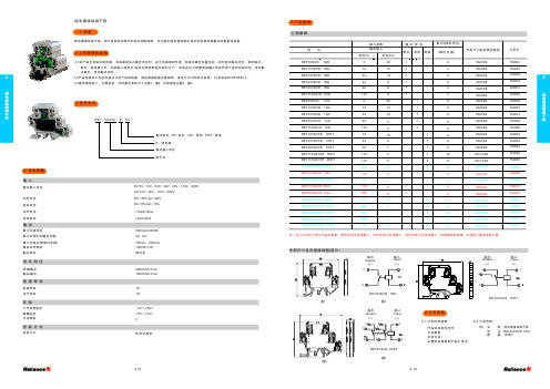
3 型号含义
4 技术参数
输入
额定输入电压
动作电压 返回电压 动作时间 返回时间
输出
最大切换电压 最大切 换电流(阻性负载) 最大 切 换 功 率(阻 性 负 载) 最高动作频率 触点材料
如需要其他规格可按用户要求单独订做继电耦合器返回电压返回时间输入动作电压额定输入电压动作时间最大切换电压最大切换功率阻性负载最高动作频率触点材料测试耐压使用寿命绕组触点机械寿命触头触点电气寿命dc12v24v48v60v110v220vac24v48v110v220v250vac30vdc2kva25kva4kva1800次小时银合金4技术参数输出最大切换电流阻性负载8a10a16a安装方式rtr35环境安装方式107105res72rx支架式设计序号工作环境温度1055储藏温度污染等级257022工作原理和结构继电耦合器用于各种自动保护和自动控制线路作为输出继电器或增加保护和控制回路触点的数量和容量
订货号
767068 767061 767077 767097 767101 767063 767102 767103 767107 767059 767108 767051 767047 767098 767062 767099 767100 767104 767064 767105 767106 767109 767057 767110 767053 767049 767086 767082 767072 767078 767080 767079 767076 767075 767052 767048 767054 767055 767085 767074 767081 767067
- 1、下载文档前请自行甄别文档内容的完整性,平台不提供额外的编辑、内容补充、找答案等附加服务。
- 2、"仅部分预览"的文档,不可在线预览部分如存在完整性等问题,可反馈申请退款(可完整预览的文档不适用该条件!)。
- 3、如文档侵犯您的权益,请联系客服反馈,我们会尽快为您处理(人工客服工作时间:9:00-18:30)。
H J S T
Header for 2.5mm (.098") pitch XA
connector for use specifically with resin coated ("potted") PC boards
Features ––––––––––––––––––––––––
• Header for 2.5mm (.098") pitch XA connector for use specifically with resin coated ("potted") PC boards
This header is tall and fully shrouded so as to prevent the resin used to coat the PC board from coming into contact with the mating pins.
• Interchangeability
Designed to accept XA mating receptacles.
Specifications –––––––––––––––––––
• Current rating:3A AC, DC (AWG#22)• Voltage rating:250V AC, DC
• Temperature range:-25˚C to +85˚C
(including temperature rise in applying electrical current)
• Contact resistance:Initial value/10m Ωmax.
After environmental testing/20m Ωmax.
• Insulation resistance:1,000M Ωmin.
• Withstanding voltage:1,000V AC/minute • Applicable wire:AWG #28 to #22
• Applicable PC board thickness: 1.6mm (.063")* Contact JST for details.
Standards ––––––––––––––––––––––
0Recognized E60389
1Certified LR208122
R9851220
Disconnectable Crimp style connectors
XA CONNECTOR
High box type
Radial Tape
Contact –––––––––––––––––––––––––––––––––––––––––––––––––––––––––––––––––
Housing –––––––––––––––––––––––––––––––––––––––––––––––––––––––––––––––––
XA CONNECTOR
High box type
Retainer –––––––––––––––––––––––––––––––––––––––––––––––––––––––––––––––––
<For reference>As the color identification,
the following alphabet shall be put in the underlined part.
For availability, delivery and minimum order quantity, contact JST.
ex.
XAP-02V-1-oo -(blank)…natural (white)
K…black R…red E…blue M…green Y…yellow
Shrouded header –––––––––––––––––––––––––––––––––––––––––––––––––––––––––
XA CONNECTOR
High box type
Shrouded header on radial-tape –––––––––––––––––––––––––––––––––––––––––––––
<For reference>As the color identification,
the following alphabet shall be put in the underlined part.
For availability, delivery and minimum order quantity, contact JST.ex.
BH02B-XASK-BN -S…natural (ivory)
K…black R…red M…green Y…yellow
Packaging specifications –––––––––––––––––––––––––––––––––––––––––––––––––––
Products of different packaging specifications sre also available.Contact JST for details.
XA CONNECTOR
High box type
PC board layout
(viewed from component side)and Assembly layout ––––––––––––––––––
Note:
1. Tolerances are non-Cumulative: ±0.05mm( ±.002") for all centers.
2. Hole dimensions differ according to the kind of PC board and piercing method.The dimensions above should serve as a guide line. Contact JST for details.
Taping specifications ––––––––––––––––––––––––––––––––––––––––––––––––––––––
Applicator for the semi-automatic press AP-K2N–––––––––––––––––––––––––––––––。