电暖气说明书模板
电取暖控制器使用说明书
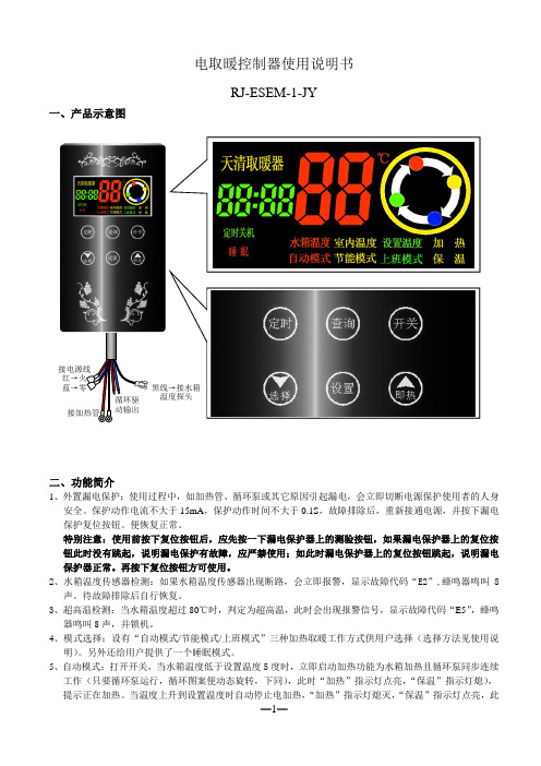
电取暖控制器使用说明书RJ-ESEM-1-JY一、产品示意图二、功能简介1、外置漏电保护:使用过程中,如加热管、循环泵或其它原因引起漏电,会立即切断电源保护使用者的人身安全。
保护动作电流不大于15mA ,保护动作时间不大于0.1S ,故障排除后,重新接通电源,并按下漏电保护复位按钮。
便恢复正常。
特别注意:使用前按下复位按钮后,应先按一下漏电保护器上的测验按钮,如果漏电保护器上的复位按钮此时没有跳起,说明漏电保护有故障,应严禁使用;如此时漏电保护器上的复位按钮跳起,说明漏电保护器正常。
再按下复位按钮方可使用。
2、水箱温度传感器检测:如果水箱温度传感器出现断路,会立即报警,显示故障代码“E2”,蜂鸣器鸣叫8声。
待故障排除后自行恢复。
3、超高温检测:当水箱温度超过80℃时,判定为超高温,此时会出现报警信号,显示故障代码“E5”,蜂鸣器鸣叫8声,并锁机。
4、模式选择:设有“自动模式/节能模式/上班模式”三种加热取暖工作方式供用户选择(选择方法见使用说明)。
另外还给用户提供了一个睡眠模式。
5、自动模式:打开开关,当水箱温度低于设置温度5度时,立即启动加热功能为水箱加热且循环泵同步连续工作(只要循环泵运行,循环图案便动态旋转,下同),此时“加热”指示灯点亮,“保温”指示灯熄), 提示正在加热。
当温度上升到设置温度时自动停止电加热,“加热”指示灯熄灭,“保温”指示灯点亮,此时循环泵继续运行2分钟后,再以3分钟停止2分钟运行的方式持续工作。
当水箱温度再次低于设置温度5度时,立即启动加热且循环泵同步连续工作。
当水箱温度再次上升到设置温度时,停止加热,循环泵继续运行2分钟后,以3分停止2分运行的方式持续工作。
如此循环。
如在加热期间按动开关键会进入关机状态,也将会停止加热。
6、节能模式:在打开开关时,当加热条件成立,启动加热功能为水箱加热且循环泵同步连续工作(只要循环泵运行,循环图案便动态旋转,下同),加热期间循环泵连续工作,加热停止期间循环泵按2分钟运行3分钟停止的方式持续工作。
电子暖气商品说明书
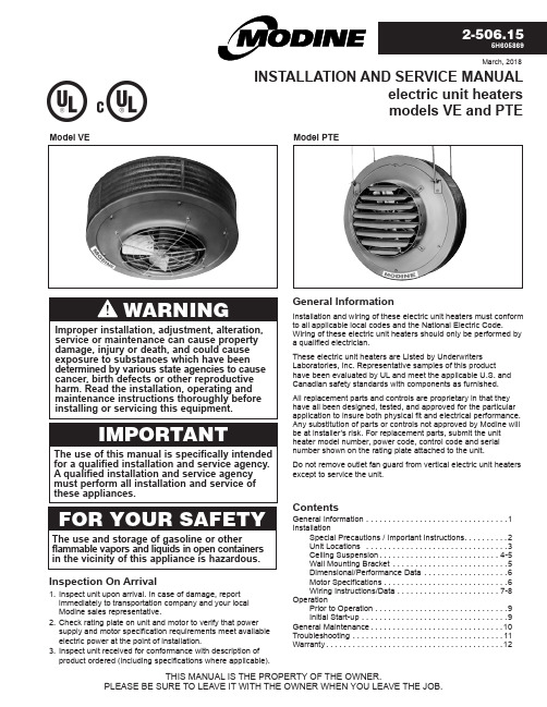
Inspection On Arrivalnspect unit upon arrival. In case of damage, report immediately to transportation company and your local Modine sales representative.heck rating plate on unit and motor to verify that power supply and motor specification requirements meet available electric power at the point of installation.nspect unit received for conformance with description of product ordered (including specifications where applicable).THIS MANUAL IS THE PROPERTY OF THE OWNER.PLEASE BE SURE TO LEAVE IT WITH THE OWNER WHEN YOU LEAVE THE JOB.Model PTEWARNINGIMPORTANTThe use of this manual is specifically intended for a qualified installation and service agency. A qualified installation and service agency must perform all installation and service of these appliances.FOR YOUR SAFETYThe use and storage of gasoline or otherflammable vapors and liquids in open containers in the vicinity of this appliance is hazardous.Improper installation, adjustment, alteration, service or maintenance can cause property damage, injury or death, and could cause exposure to substances which have been determined by various state agencies to cause cancer, birth defects or other reproductive harm. Read the installation, operating and maintenance instructions thoroughly before installing or servicing this equipment.SPECIAL PRECAUTIONS / IMPORTANT INSTRUCTIONS22-506.152-506.15In locating heaters, consider general space-heating requirements of the area. Unit heaters should be located so that exposed walls are blanketed with warm air. In multiple unit installations, arrange units so that the air discharge pattern of one unit overlaps the next unit thus encompassing the area (See Fig. 3.1 & 3.2). Interference of air streams by columns, beams, partitions or other obstructions should be avoided as much as possible.Locating Unit HeatersFigure 3.1 - Typical Unit Locations for HorizontalAir DeliveryFigure 3.2 - Typical Unit Locations for Vertical DeliveryINSTALLATIONTable 3.1 - Maximum Mounting Heights/Spreads (feet) ➀➀ T he maximum mounting heights consider air delivery to be from the bottom of the unit to the floor based on conditions in Table 6.2. Refer to Figure 3.3.It is recommended that adequate service access in excess of 18 inches be provided for the motor and fan.Vertical Delivery No Deflector Truncone Cone Jet Louvers Model Blades Open Blades Open Blades 45° H S H S H S H S H S VE50 13 20 9 24 18 23 15 13 8 23 VE75 11 17 8 20 15 20 13 11 8 20 VE100 12 18 8 22 17 22 14 12 8 22 VE150 17 26 11 30 23 30 20 17 10 30 VE200 20 30 13 36 27 35 23 20 12 35 VE250 17 26 11 31 23 31 20 18 10 31 VE300 20 31 15 36 28 36 24 21 12 36 VE400 18 27 13 32 24 32 21 18 11 32 VE500 16 24 12 29 22 29 19 16 10 29Height at which unit heaters are installed is critical. Maximum mounting heights for vertical units are listed in T able 3.1. Maximum mounting heights for PTE units are listed inFigure 4.2. The maximum mounting height for any unit is that height above which the unit will not deliver heated air to the floor. The maximum mounting heights must not be exceeded in order to assure maximum comfort.WITH CONE-JETSHFigure 3.3 - Vertical Delivery Heat Spread/ThrowUnit MountingIf necessary, select the correct deflector assembly toaccommodate the area being covered. Note the louver deflector data in the table is listed with louvers fully open and withadjusting vanes set at a 45-degree angle. For these deflectors, vane adjustment provides a greater spread but requires a lower mounting height. As indicated, truncone deflectors allow the lowest mounting height and provide the widest heat spread.Figure 3.4 - Vertical Deflector DimensionsTRUNCONECONE-JETLOUVERSMXLTZIf an optional air deflector has been furnished for vertical units it is always shipped separately and may be attached to the unit before suspension. Louvers on horizontal units may also be added and positioned before installation. Refer to the latest revision of 75-550 for installation instructions for the optional air deflector assemblies.Table 3.2 - Vertical Deflector Dimensions (inches)Model Truncone Cone-Jet Louvers No. M X L T P Z VE50-VE250 12 1/2 22 6 1/2 18 7/8 6 1/2 16 7/8 VE300-VE-500 12 1/2 27 7 1/2 24 3/4 7 1/2 19 3/432-506.15Model PTE Unit SuspensionModel PTE electric heaters are provided with four hanger brackets for installation with four ceiling suspension rods (5/8-inch diameter), furnished by others. Refer to Figures 4.4 and 5.1.NOTE: A pipe hanger adapter kit is available as an accessory from Modine. The kit consists of two drilled 3/4'' I.P .S. pipe caps and two 1/2''-13 x 1 3/4'' capscrews to facilitate threaded-pipe suspension. Two kits are required to pipe-mount a vertical unit. Kit is not available on 480-volt models, VE50 thru VE250 with transformer junction box.INSTALLATIONFigure 4.4 - Ceiling-mounted Model PTEAccessory InstalledANGLE BRACKET FASTENINGFigure 4.2 - Horizontal Delivery with Louver Deflectors (Models PTE300, PTE400, PTE500)MODEL HEIGHT (H) THROW (T)PTE300 17 75PTE400 15 60PTE500 14 45HTBe sure the means of suspension is adequate to support the weight of the unit. For proper operation, the unit must be installed in a level horizontal position. Clearances tocombustibles as specified above must be strictly maintained. Do not install unit heater above the maximum mounting height shown in Table 3.1 for VE models or Figure 3.4 for PTE models or below eight feet.42-506.15For easier installation of PTE model electric unit heaters, where ceiling suspension is not feasible, a wall-mounting bracket kit is available. The bracket saves installation time, has a built-in 5DIMENSIONAL/PERFORMANCE DATA62-506.152-506.15INSTALLATION - ELECTRICAL CONNECTIONSPOWER TERMINAL BLOCKCONTROL TERMINAL BLOCKGROUND LUGCONTACTORTRANSFORMERFUSE BLOCK W/FUSES7INSTALLATIONOVERHEAT CONTROL ELEMENT CONNECTION POWER SUPPLY OPENINGWIRING OPENING 82-506.15OPERATION217896 54 3Operating SequenceThe operation of Modine electric unit heaters is governed byan electrical contactor which is controlled by a thermostat. The contactor completes the electric circuit to the heating elements when the thermostat “calls” for heat. The fan motor is also activated when the thermostat “calls” for heat.When the thermostat is satisfied, the fan motor stops and the contactor opens the circuit to the heating elements.Prior to OperationAlthough this unit has been inspected and tested at the factory, the following procedures should be performed to assure proper on-site operation.Check fan clearance. Fan should not contact casing or fan guard when spun by hand.Check all electrical connections to be sure they are secure, and in accordance with the wiring diagram.Check firmness of unit suspension. Tighten all fasteners, if necessary.Make sure fuses are installed in units that require them.Safety DevicesThe overheat control, (See Figure 9.1), will interrupt power to the unit contactor in the event of overheating. It is a single-pole single-throw switch, with an automatic reset. The switch will permit the motor to continue operation and cool the heater while power to the elements is interrupted. This overheat control should operate only when something is seriously wrong with the unit. When this control operates, correct the difficulty immediately or serious and permanent damage may result.The motor for the circulating air fan has internal thermal overload protection. If for any reason, the motor overheats,the thermal protector will shut it off. The motor will re-start automatically when it has cooled.Initial Start-Up1. Adjust room thermostat above room temperatures.2. Turn on power to the unit.3. Adjust the air deflector (if provided) for desired heatdistribution.4. Run the unit through several cycles by raising and loweringthe thermostat setting to assure proper sequence ofoperation. For Models VE and PTE300, 400, 500 withtwo-stage thermostats, check operation on both states.Three elements should heat up during first stage operation when temperature falls. As additional heat is requiredthe remaining three elements will be energized until thethermostat high-stage setting is satisfied. The unit willautomatically shut off when the low-stage thermostat setting is satisfied.92-506.15GENERAL MAINTENANCE102-506.15TROUBLESHOOTING112-506.15COMMERCIAL WARRANTYSeller warrants its products to be free from defects in material and SHALL, WITHIN THE APPLICABLE WARRANTY PERIOD DEFINED HEREIN© Modine Manufacturing Company 2018。
取暖器说明书

六、电气原理图(花篮式) (升降式、落地式)取暖器七、故障处理使用说明书1.电暖器不发热,开机3分钟无发热感,请检查电源是否正常,插头是否良好,检查 后再试之。
2.第一次使用,发热时会有小量白烟气和有一些异味出现属正常现象。
3.摇头时发生异样声音,可适当调节柱头螺口。
八、保修卡(为确保您的利益,请您妥善保管《产品保修卡》以作保修之用。
)◆ 亲爱的用户:请仔细阅读此说明,并特别注意安全说明,保留此手册以备将来不时之需。
本说明书中的内容可能因为产品改进原因导致与实物有一定的出入,请以实物为准。
产品保修卡 用 用户姓名: 联系电话 户 通讯地址:填 邮编: 写 产品型号/货号: 发票编号: 经销商签字/盖章: 出售日期:维修情况记录第一次维修 维修日期: 维修类别:维修单位签/章; 第二次维修 维修日期: 维修类别:维修单位签/章:产品维修时请带上此卡和有效收费发票(收据)带有定时器的取暖器,定时器旋钮顺时针拧动可任意定时在0-60分钟范围内。
尊敬的顾客 C.俯仰调节;感谢您使用本公司生产的多功能取暖器,使用前请仔细阅读使用说明书,并依照指导用手扳动上下机体的头部,即可在俯角40°范围内调整你所需的角度。
(台式取暖器没有此功能)正确使用和维护保养好您的器具。
D.摇摆控制;本公司生产的小太阳电暖器采用速暖红外辐射加热技术,使人体迅速直接感受到热能。
带有摇头功能的电暖器,若需要取暖器送暖,只需用手按下摇头键,如果要定向送暖,只需再次起动摇头一、性能特点键即可。
·采用充有卤素气体且完全密封的环形卤素管或远红外电热丝。
使用寿命长,开机后注;没有摇头功能的电暖器不能参照摇头挡。
加热速度快,电热转换率高。
E.升降控制;·抛物面聚能反射,势力强劲。
升降使用时,根据需要作升降高度调节,左手握升降杆,右手按升降按钮,机头将自动升高,要下降时,·超远距离及大角度摇头送暖和俯仰,升降随意调节按机头往下压。
技术规格书(电暖气)
电暖气技术规格书1、规范及标准本用户需求书主要执行和参考以下标准和规范(如下述内容不为最新版本,需按最新版本采用):《建筑设计防火规范》(GB50016-2014)《民用建筑供暖通风与空气调节设计规范》(GB50736-2012)《铁路房屋暖通空调设计标准》(TB10056-98)其它相关的规范和标准。
2、技术要求1、供电电源:单相交流220V/50Hz。
2、自带温度传感器、电子控温装置,温度设置按钮,壁挂式安装。
3、自带恒温功能,在室内温度自动恒定在设置温度上,室内温度达到20℃时自动关闭,低于15℃时自动开启。
4自带防漏电及过热保护装置5、设备表面应清洁、平整、无碰伤、划痕及锈斑;漆层牢固、色泽均匀一致,无起泡、缩皱和剥落现象。
3 设备及材料本工程所有选用的设备以及配套所用材料和零件均应为未经使用过的合格产品,不存在任何影响到性能的缺陷。
所有电气元件和材料应符合国家有关规范和标准的要求。
4 保证在购买方选用设备恰当和遵守保管及使用规程的条件下,最少需要承诺免费保修3年以上,其它配套设备及材料保修一年。
另外,因设备制造质量不良及设备材料本身质量不良而发生损坏和不能正常工作时,供货方应该免费为购买方更换或修理设备零件、部件,如因此而造成购买方人身和财产损失的,供货方应对其予以赔偿。
5、性能保证除非购买方以文字的方式另行同意,供货方对它所提供的设备应承担如下保证:在数据表中规定的工作条件下能正常可靠地运行,并达到额定地设计参数。
通过试验证实供货方对各项性能方面地保证。
7、检验、试验和证书6、质量标准供货商在投标文件中应包括:质量证书、即ISO9001认可,质保体系、检查和试验的计划,用户清单7、证书检验和试验报告:供货方提供单台试验和检验报告。
检验证书:供货方提供工厂出具的具有效力的检验证书一式两份。
出厂合格证书:每台设备均具有合格证书,并注明型号、规格、适用介质、制造商名称、生产日期。
8、标志为了正确使用和维护检修等,装置必须设置各种标志来证明其电气参数、使用条件、正确的操作和元件的更换。
电暖器操作和安全说明书
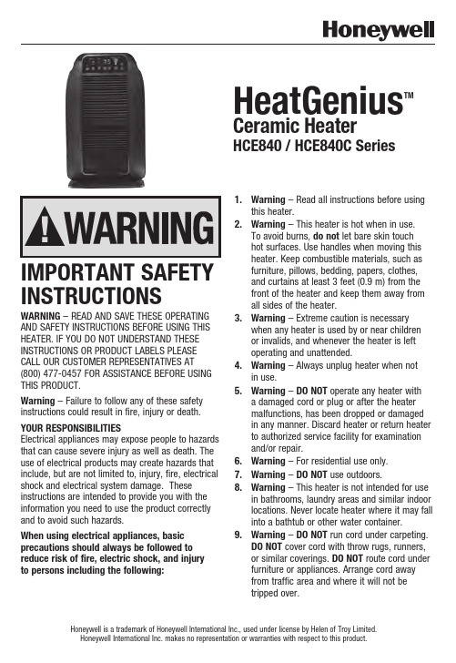
INSTRUCTIONSWARNING – READ AND SAVE THESE OPERATING AND SAFETY INSTRUCTIONS BEFORE USING THIS HEATER. IF YOU DO NOT UNDERSTAND THESE INSTRUCTIONS OR PRODUCT LABELS PLEASE CALL OUR CUSTOMER REPRESENTATIVES AT (800) 477-0457 FOR ASSISTANCE BEFORE USING THIS PRODUCT.Warning – Failure to follow any of these safety instructions could result in fire, injury or death. YOUR RESPONSIBILITIESElectrical appliances may expose people to hazards that can cause severe injury as well as death. The use of electrical products may create hazards that include, but are not limited to, injury, fire, electrical shock and electrical system damage. These instructions are intended to provide you with the information you need to use the product correctly and to avoid such hazards.When using electrical appliances, basic precautions should always be followed to reduce risk of fire, electric shock, and injury to persons including the following:1.Warning – Read all instructions before usingthis heater.2.Warning – This heater is hot when in use.To avoid burns, do not let bare skin touchhot surfaces. Use handles when moving thisheater. Keep combustible materials, such asfurniture, pillows, bedding, papers, clothes,and curtains at least 3 feet (0.9 m) from thefront of the heater and keep them away fromall sides of the heater.3.Warning – Extreme caution is necessarywhen any heater is used by or near childrenor invalids, and whenever the heater is leftoperating and unattended.4.Warning – Always unplug heater when notin use.5.Warning – DO NOT operate any heater witha damaged cord or plug or after the heatermalfunctions, has been dropped or damagedin any manner. Discard heater or return heater to authorized service facility for examinationand/or repair.6.Warning – For residential use only.7.Warning – DO NOT use outdoors.8.Warning – This heater is not intended for usein bathrooms, laundry areas and similar indoor locations. Never locate heater where it may fall into a bathtub or other water container.9.Warning – DO NOT run cord under carpeting.DO NOT cover cord with throw rugs, runners,or similar coverings. DO NOT route cord underfurniture or appliances. Arrange cord awayfrom traffic area and where it will not betripped over. HeatGenius TM Ceramic HeaterHCE840 / HCE840C SeriesHoneywell is a trademark of Honeywell International Inc., used under license by Helen of Troy Limited.Honeywell International Inc. makes no representation or warranties with respect to this product.© 2016 All Rights Reserved.Kaz USA, Inc., a Helen of Troy CompanyMarlborough, MA 01752Honeywell is a trademark of Honeywell International Inc., used under license by Helen of Troy Limited.Imported and Distributed by: Kaz Canada, Inc., Milton ON, L9T 2X6Contact us at 1-800-477-0457 or /heaters© 2016 Tous droits réservés.Kaz USA, Inc., une société de Helen of TroyMarlborough, MA 01752Honeywell est une marque de commerce de Honeywell International, Inc. qu’utilise Helen of Troy Limited sous licence. Importé et distribué par : Kaz Canada, Inc., Milton ON, L9T 2X6Pour nous joindre, composez le 1 800 477-0457 ou visitez /heaters© 2016 Todos los derechos reservados.Kaz USA, Inc., una Empresa de Helen of TroyMarlborough, MA 01752Honeywell es una marca registrada de Honeywell International Inc., utilizada bajo licencia por Helen of Troy Limited. Importado y Distribuido por Kaz Canada, Inc., Milton ON, L9T 2X6Contáctenos al teléfono 1-800-477-0457 o al sitio web /heatersP/N: 31IMHC84190R002MAR16For Responsible recycling, please visit: Para reciclar responsablemente, por favor visite:。
暖煌电暖器说明书
暖煌电暖器说明书
一、仔细阅读说明书。
说明书上不但有对产品性能的介绍,更重要的是说明书上有关于本款产品的使用须知和安全使用的注意事项,所以建议每一位用户在使用前认真阅读说明书,不要认为产品简单或自己会使用,就忽略说明书。
二、电暖器的电源必须使用合格的、带地线的三孔插座,否则会有漏电的危险。
电暖器功率较大,不宜与大功率的电器以及电焊机、冲击钻等同时使用,注否则容易损坏电暖器。
此外,插座不能位于电暖器正上方,以防热量上升烧烫电源。
当居室中无人时,一定要把电暖器电源拔掉。
三、小心开关的使用。
一些质量比较好的.产品在开关处都会有绝缘的保护胶盖,以防
有漏电的危险,在连接上电源后,建议先开最小档,因为这个时候机体刚刚预热,如果一下子开到最大档,对机体有损伤,而且过强的电流冲击,也可能造成危险。
在不使用时,一定要关闭开关,先关闭机体上的功率开关,再拔掉电源,这样减少危险。
四、使用电暖器要注意安全距离。
电暖器的使用要格外的慎重,由于电暖器在运作时机体温度很高,所以尽量要离人体1米左右的距离,不能够放置在电视机以及家居柜子旁边,以免引起产品的损坏和变形。
不能覆盖物品,特别是衣服或棉被之类,一旦覆盖物品,电暖器机体的热量不能及时散发,会造成
烧机和发生火灾的危险。
应放在不易碰触的地方,远离可燃烧物品和有明火的地方。
Warmup 电线板暖气说明书

Foil HeatersThis manual contains IMPORTANT information regarding the safe use and installation of your foil heaters. Please read through the entire manual carefully before you install or use the product.Before installing your new Warmup® Foil heater, be sure that you have the following additional parts:• The customized installation plan (or layout) • A Warmup® Thermostat• Digital ohm meter (multi-meter)• 30mA RCD• Electrical Junction box • Electrical conduit •Insulation materialWarmup® Foil mats must be fitted directly on top of the Insulation, and directly under the wood laminate flooring.Before installation always check the subfloor has adequate thermal insulation. This is particularly important where the foil heaters will be used as a primary heat source. A heat loss calculation MUST be carried out to ensure that the product will provide enough heat for your room. See page 7 for information on suitable insulation materials.2Calculate the area of the floor to be heated. This is the total floor area minus any permanent fixtures.Length x width = m ²Select the heating mat or combination of mats closest in size to the area you want to heat. See page 6 for the full range of heater sizes. . Remember Heaters cannot overlapHeaters must be connected in parallelA single thermostat can control up to handle loads up to 16 Amps.DON’T:DON’T use the foil heating mats with glued locking systems or laminatesthat have an underpad or cushion material pre-attached to its underside.DON’T install the foil heater up steps.DON’T install over floors that have traces of moisture, are uneven,have carpets or parquet floor.DON’T l eave insulating materials such as bean bags; linen or towels on the floorsurface.DON’T overlap heating mats, fold or wrinkle the foil heating mats.DON’T place heavy/sharp tools (or any other potentially damaging object) on top of the heating mats.DON’T walk unnecessarily on the foil heating mats.DON’T install mats when the room temperature is below -5ºC.DON’T install foil heating mats anywhere except inside buildings.DON’T i nstall foil mats under walls or partitions, or in areas under heavy cabinets, closets, or fixtures (toilets, sinks, tubs, etc.).DON’T install foil mats within approximately 50mm of any heat conductive buildingpart, such as cold water pipes.DON’T install foil mats within 20mm of one another, 50mm of any wall or 100mm of af ireplace or hot water pipe.DON’T install foil heating mats under wooden floor, if the floor is thicker than 18mm.DON’T use this heater directly under any floor covering other than wood or laminate. DON’T place items on the floor surface which will stop the air flow or not allow heat to rise into the room.DON’T install electrical cables or pipes under the floor with the foil heating mats.DON’T use cellulose insulation.DON’T install the heating mats direct contact with a cement or concrete slab.The heater must be installed on top of a suitable soft Insulation material.3ALWAYS:ALWAYS c heck with the manufacturer of your flooring, that their products are compatible with electric floor heating systems.ALWAYS operate the heating mat with a Warmup® floor sensor thermostat to ensure the floor does not exceed the maximum temperature of the wood laminate(usually 27°C).ALWAYS ensure all earth leads are connected to the earth ring.ALWAYS ensure that the system is operated with a Warmup® thermostat in floorsensor mode.ALWAYS connect all cold wire leads from the foil heating mats in parallelinside an electrical junction box.ALWAYS zone each room with a foil heating system with its own thermostat controller.This allows each room to be controlled individually saving you energy byonly heating the zone when required. Each Warmup® thermostat has amaximum capacity of 16 Amps.ALWAYS ensure that no sharp edges (e.g. metal-edged laminate locking systems)come in contact with the foil heating.ALWAYS install a soft insulation / underlay below the heating mats to preventdamage when the weight of the floor furniture etc is added. Make sureunavoidable wooden floor movements will not harm the foil mats .ALWAYS ensure that a heat loss calculation has been carried out and heatingrequirements have been met if you are using the Foil heating system as aprimary source of heating.ALWAYS ensure that the heaters are protected by a 30mA RCD.ALWAYS ensure that the control card at the back of the manual is completed andfixed at the main consumer unit along with any plans and electrical testrecords. As per the current BS7671 wiring regulations.ALWAYS use the foil strips provided to bridge any gaps when cutting and turning the mats. This is important to keep the earth intact.405Construction:The Warmup® Foil system is constructed using dual core fluoropolymer insulated heating cables sandwiched between two layers of specially reinforced aluminium foil.The aluminium foil along with the uniform spacing of the heating elements ensures even heat distribution. The heating elements are connected to the power supply cable, which exits the mat from one corner.The Foil Heaters must not be installed in thinset cement or in direct contact with acement or concrete slab. The heater must be installed on top of a suitable soft Insulation material . The Warmup® Insulation board may be used if additional levels of insulation are required but a soft underlay will need to be installed on top of the board.If a vapour barrier is to be installed it should be laid below the insulation and not on top of the heater.1. Wood/ Laminate flooring2. Warmup® Foil Heater3. Soft Insulation Material4. Subfloor1. Wood/ Laminate flooring2. Warmup® Foil Heater3. Underlay4. Warmup® Insulation Board5. SubfloorInstallation Examples6Model Area (m 2)Length (m)Width (m)Total Watts Amps Total Resistance WLFH-140W/140120.51400.61377.86WLFH-140W/210 1.530.52100.91251.90WLFH-140W/280240.5280 1.22188.93WLFH-140W/420360.5420 1.83125.95WLFH-140W/560480.5560 2.4394.46WLFH-140W/7005100.5700 3.0475.57WLFH-140W/8406120.5840 3.6562.98WLFH-140W/9807140.5980 4.2653.98WLFH-140W/11208160.51120 4.8747.23WLFH-140W/12609180.51260 5.4841.98WLFH-140W/140010200.51400 6.0937.79WLFH-140W/168012240.516807.3031.49Model Area (m 2)Length (m)Width (m)Total Watts Amps Total Resistance WLFH-80W/80120.5800.35661.25WLFH-80W/120 1.530.51200.52440.83WLFH-80W/160240.51600.70330.63WLFH-80W/240360.5240 1.04220.42WLFH-80W/320480.5320 1.39165.31WLFH-80W/4005100.5400 1.74132.25WLFH-80W/4806120.5480 2.09110.21WLFH-80W/5607140.5560 2.4394.46WLFH-80W/6408160.5640 2.7882.66WLFH-80W/7209180.5720 3.1373.47WLFH-80W/80010200.58003.4866.13140W80WPlease ensure that your laminate flooring is suitable for use with electric underfloor heating.Most wood / laminate floors are compatible with the Foil mats but we do not recommend using any wood flooring thicker than 18mm.Wood flooring with metallic strips as part of their locking systems are NOT compatible as these metallic strips may damage the Foil mats.Any wood floor with a pad already attached must not be used with the Warmup® Foil mats.For a wooden floors or similar the thermal resistance should not exceed 0.15m ²K/W.TopBottomThe Foil Heaters MUST NOT be installed in thinset cement or in direct contact with a cement or concrete subfloor. The heater MUST be installed on top of a suitable soft Insulation material. ThisAs with all electrical projects which are subject to Part P , all electrical work must be carried out by a certified electrician. All work must conform to the current IEE wiring regulations - BS7671.The system must be protected by a dedicated 30mA RCD at all times. For systems not exceeding 13 amps a fused spur or 30mA RCD/spur that has contact separation in all poles that pro-vides full disconnection under over-volt-age category III conditions must be used.For systems larger than 13 amps a suitable protective device that meets the current wiring regulations must be used.Connecting the thermostatThe thermostat should be installed in the room to be heated. In the case of bath-rooms or wet areas a electrician should be consulted regarding whether a suitable zone is available.The thermostat can handle a load up to16 amps. For larger installations exceeding 16 amps multiple thermostats may be required or it may be possible to use a Contactor.Once all of the connections have been made, the electrician must complete the relevant forms and display at the fuse board as per BS7671, Section 753.8A resistance tests should be carried out on the heating mat before, during and after fitting the final floor covering.Using a Multi-meter set at 2K ohms test across • Live to neutral = ohms value as listed on Page 6If you do not get the expected results or at any time you believe there may be a problem, please contact Warmup’s Technical Team for guidance.Record the readings on the control card at the back of the manual.NOTE: Ensure that the floor sensor is tested before the final floor finish has been laid. The floor sensor values can be found in the thermostat instructions. When testing the floor sensor ensure that the meter can read up to 20k ohms.Before installing, draw an installation plan showing the placement of the mats, floor sensor, and junction box or boxes.The Foil heating mats should cover at least 80-90% of the floor area of your room to be used as a primary heat source*.Choose the combination of heating mats that best enables you to cover the recommended 80-90% of your room. Plan to use the larger foil heating mats as much as possible and to use smaller mats only as gap fillers.Note: The mats are supplied with a 3 metre long electrical cold lead. If you need longer connection leads, these may be extended consult a qualified electrician.*Depending on insulation, air-flow & overall heat-loss within the room, additional heating may be required.It is important to keep an accurate record of where the mats are installed.The Foil heater MUST NOT be installed in thinset cement, or indirect contact with a cement or concrete subfloor.There must always be a soft insulation / underlay beneath thealuminium heating mats.Carefully inspect the subfloor and make sure it is clean, free ofsharp edges, protruding nails and any other materials that maydamage the heating mat.Lay the Insulation as per the manufacturer instructions.If you are using the Warmup® insulation board you will need toinstall a soft underlay on top of the boards.Remove the foil heating mat from the packaging and check themats visually for any damage.Test using a multi-meter and verify the correct resistance againstthe table on page 6. Record the readings on the control card at theback of the manual.910Roll out the foil heating mats on top of the insulation material. Keep the heating mat at least 50mm from the edges of the room. Ensure that the heating mat is completely flat. Care should be taken not to fold or crease the mats at any time during installation.Position it in such a way that the power cord will be able to reach the point where the thermostat will be connected.If fitting more than one foil heating mat ensure that the mat does must not overlap, as overheating will result. Leave a gap of at least 20mm between each mat. Secure the foil mat to the underlay using tabs of duct tape to hold the mat in position.If any of the wire has been detached from the foil mat (when the mat is cut and turned) the wire MUST be covered by the aluminium strips. The aluminium strips should also be used to bridge the gap between the sections of the mat.NOTE: This is essential in order to keep the earth circuit intact.Secure the mats to the floor with tabs of duct tape. Since the joint and the cold tail leads are slightly thicker than the rest of the mat, you will need to create a slight groove in the insulation to ensure the heating mat lays flat. Do not allow the power supply cable to cross or come into contact with the heating mat.Once the heater(s) have been laid mark each pair of coldtail leads coming from the same mat with a numbered sticker This will make it easier to identify each mat once the floor coveringis laid.Position the sensor approximately 300mm into the heated area in-between the heating wires runs on the mat.Do not allow the sensor tip to come into contact with any of the heating element wires.Warmup recommend the use of conduit when installing the floor sensor. The conduit will protect the sensor and will allow for easier replacement should there be a problem after flooring has been laid.Run the sensor cable back to the thermostat. The sensor wire MUST not cross over the foil heater wires.Test the floor sensor using a multi-meter. The floor sensor ohms reading values can be found in the thermostat instructions.11Before fitting the final floor covering test the heating mats to ensure that they have not been damaged during installation. See page 8 for details.You are now ready to lay the final floor finish. Take care not to damage the heating mats. Do not drive nails or screws into the floor or cut the floor panels on top of the heater.If the floor is not being laid immediately, all heating mats must be protected with cardboard to prevent damage. Immediately prior to the floor being laid, test the heating mat to ensure it has notbeen damaged.Once the flooring has been installed, connect the thermostatensuring that it is set to reach a maximum temperature of 27°C.A Warmup® thermostat with a floor sensor MUST be used inorder to accurately monitor the floor temperature and yourcomfort level.Always zone each room with a foil heating system with its ownthermostat controller. This allows each room to be controlledindividually saving you energy by only heating the zone whenrequired.WARNING:ELECTRICAL WORK WHICH IS SUBJECT TO PART P BUILDING REGULATIONS MUST BE CARRIEDOUT BY A QUALIFIED ELECTRICIAN.ALL WORK MUST CONFORM TO THE CURRENT IEE WIRING REGULATIONS.1213Register your Warmup ® Warranty online at Warmup ® Foil Heater is guaranteed by WARMUP PLC (“Warmup”)to be free from defects in materials and workmanship under normal use and maintenance, and is guaranteed to remain so subject to the limitations and conditions described below.The Warmup® Foil Heater is guaranteed for 15 Years from the date of purchase against manufacturing defects. The 15 year guarantees applies:1. Only if the unit is registered with Warmup within 30 days after purchase. Registration can be completed online at . In the event of a claim, proof of purchase is required, so keep your invoice and receipt - such invoice and receipt should state the exact model that has been purchased ; and2.Only if the heater has been earthed and protected by a 30mA RCD at all times. Thermostats are guaranteed for a period of 3 YEARS from the date of purchase.Neither guarantee continues if the floor covering over the heater(s) is damaged, lifted, replaced,repaired or covered with subsequent layers of flooring.This guarantee period begins on the date of purchase. Registration is confirmed only when confirmation is sent by Warmup PLC.During the period of guarantee Warmup will arrange for the heater to be repaired or (at its discretion) have parts replaced free of charge. The cost of repair or replacement is your only remedy under this remedy under this guarantee which does not affect your statutory rights. Such costs does extend to any cost other than direct costs of repair or replacement by Warmup and does not extend to costs of relaying or repairing any floor covering or floor.If the heater fails due to damage caused during installation or tiling, this guarantee does not apply. It is therefore important to check that the heater is working (as specified in the installation manual) prior to installing the final floor finish.WARMUP PLC SHALL IN NO EVENT BE LIABLE FOR INCIDENTAL OR CONSEQUENTIAL DAMAGES, INCLUDING BUT NOT LIMITEDTO EXTRA UTILITY EXPENSES OR DAMAGE TO PROPERTY. Terms and conditions applyREGISTER YOUR HEATER ONLINE AT: THE 15- YEAR ELEMENT OF THIS GUARANTEE DOES NOT EXTEND TO THERMOSTATS WHICH ARE COVERED BY A 3 YEAR GUARANTEE. THIS GUARANTEE DOES NOT AFFECT YOUR STATUTORY RIGHTS.Warmup PLC is not responsible for : 1. Damage or repairs required as a consequence of faulty installation or application. 2. Damage as a result of floods, fires, winds, lightning, accidents, corrosive atmosphere or other conditions beyond the control of Warmup PLC. 3. Use of components or accessories not compatible with this unit. 4. Products installed outside the United Kingdom. 5. Normal maintenance as described in the installation and operating manual. 6. Parts not supplied by Warmup.7. Damage or repairs required as a result of any improper use, maintenance, operation or servicing. 8. Failure to start due to interruption and /or inadequate electrical service. 9. Any damage caused by frozen or broken water pipes in the event of equipment failure. 10. Changes in the appearance of the product that does not affect its performance. SafetyNet TM Installation Guidelines : If you make a mistake and damage the new heater before laying the floor covering, return the damaged heater, to Warmup within 30 DAYS along with your original dated sales receipt. WARMUP WILL REPLACE ANY HEATER (MAXIMUM 1 HEATER) WITH ANOTHER OF THE SAME MAKE AND MODEL-FREE.PLEASE NOTE: 1. Repaired heaters carry a 5 year warranty only. Under no circumstances is Warmup responsible for the repair or replacement of any flooring.2. The SafetyNet TM Installation Guarantee does not cover any other type of damage, misuse, or improper installation due to improper adhesive or subfloor conditions. Limit of one free replacement heater per customer or installer. 3.Damage to the heater that occurs after laying the floor covering is not covered by the Safety Net TM Installation.Guarantee.14This form must be completed as part of the Warmup Guarantee. Ensure that the values are as per the instruction manual.This card must be situated close to the consumer unit in a visible place.Note: Draw a plan showing the layout of the heater.Warmup plc, 702 Tudor Estate, Abbey Road, London, NW10 7UW T: 0345 345 2288 F: 0345 345 2299 0The WARMUP word and associated logos are trade marks. © Warmup Plc. 2021 - Regd. TM Nos. 1257724, 4409934, 4409926, 5265707. E & OE.Warmup plc n 704 Tudor Estate n Abbey Road n London n NW10 7UW n UK Warmup GmbH n Ottostraße 3 n 27793 Wildeshausen n DE Warmup plc ************* Tel: *********** Fax: ***********Warmup - IM - WLFH_Foil Heater - V2.6 2021-06-18_EN。
飞利浦 3000i系列 室内加热器(对流式电暖器) 使用手册说明书

前壳 散热口
控制面板
后壳 烘衣架
脚板
电源开关 脚轮
2 技术参数
型号
AHR3142CS
额定电源
220V~ 50Hz
额定功率
2000W
防水等级 备注
IPX2 电子式(WIFI款)
本产品已通过3C认证
本产品根据国标:GB4706.1 GB4706.23 制造
3 装箱单
名称 对流式电暖器 遥控器 说明书 脚板 脚轮 壁挂挂钩 膨胀螺钉 壁挂螺钉 脚板螺钉
用。
现象。
• 取暖器在工作时严禁触摸防护网罩, • 本加热器的安装要使得在浴缸内或
防止高温烫伤;请特别注意儿童。
ቤተ መጻሕፍቲ ባይዱ
淋浴区的人不能够触及到开关和其
• 为延长产品使用寿命,请不要在取
他控制器。
暖时移动取暖器。
• 因为加热器被覆盖或不正确的放置 会引起火灾,故不得利用带有可自
禁止覆盖
动接通电源的程序器,定时器或任 警告:为避免过热,禁止覆盖加热器。 何其他装置来使用本加热器。
“中档”控制面板显示2d,按第
三次为“高档”控制面板显示3d, 遥控器使用方法
本机设有三个加热档位,依次循 打开遥控器背部电池盖装上两节 7号电池,
环。
即可使用;遥控器上按“ ”键,加热档位
4. 按“ ”键本机可在1h-12h内 递减一档,按“ ”键,加热
自由定时,每按一次递增1小时, 在显示屏上均有相应的显示,当 控制面板上显示为“ ”时说 明本机连续工作。
固定牢固。
注:壁挂安装时机体不能装上脚;
安装高度最低不能低于150mm。
2
7 使用方法
使用环境温度;也可控制加热器 是否工作;例:按“ ”键将温
- 1、下载文档前请自行甄别文档内容的完整性,平台不提供额外的编辑、内容补充、找答案等附加服务。
- 2、"仅部分预览"的文档,不可在线预览部分如存在完整性等问题,可反馈申请退款(可完整预览的文档不适用该条件!)。
- 3、如文档侵犯您的权益,请联系客服反馈,我们会尽快为您处理(人工客服工作时间:9:00-18:30)。
电暖气说明书
干式铝汀安装使用说明书
适用型号:CA700A3F,CA900A3F,CA125 A3F,
CA150 A3F,CA180
A3F ,
此图片仅供参考,具体产品以实物为准,在使用本产品前请仔细
阅读说明书。
包装箱中的产品及附件:
首次打开包装箱,请检查包装箱内的如下物料
A 主机
B 落地支脚
C 固定片
D 小膨胀螺丝
E 挂钩
F 大膨胀螺丝
G 底脚螺丝
H 螺丝
I 遥控器
A
B
D E F
H I
产品目录:
型号:输出功率(W)额定电压频率片数
CA700 A3F700 220-240V~ 50Hz 4
CA900 A3F900 220-240V~ 50Hz 5
CA125 A3F1250 220-240V~ 50Hz 7
CA150 A3F1500 220-240V~ 50Hz 8
CA180 A3F1800 220-240V~ 50Hz 9 安全和注意事项:
为避免任何火灾,电击或者伤人的危险,请阅读并遵照下列说明:
1)我们的质量保证不包括因为没有遵守本说明书内容而导致的损坏。
2)产品必须接入与电器标签上的额定电压相符的电源上使用。
3)不要在煤气,炸药或易燃易爆物品附近使用本取暖器。
4)警告:为了避免产品过热,禁止用任何类似衣物,毛毯,窗帘等物品覆盖取暖器。
5)该电器运行时,产品表面温度会变高。
6)该电器不适合小孩或体弱的人在没有充分监护的情况下使用;要确保小孩不去碰触该产品。
.
7)取暖器不可直接放在电源接口下面。
8)若产品损坏或出现故障,一定要找销售代理商或者类似专业维修点进行修理,以免造成伤害。
.
9)在维护或者清理工作没有结束之前,产品一定不能连接电源。
10)请不要直接将该产品在浴室,淋浴房或者泳池附近使用。
该产品仅适用于室内使用
1.使用地点选择
1)此款产品为壁挂、落地两用取暖器,选择适当的位置安装使用
2)请勿在其它家具,窗帘或者其它电器附近安装此产品。
3)请勿在墙角安装此取暖器。
4)确保产品的安装位置远离门窗。
5)产品需要安装在正在沐浴或淋浴的人没有办法接触到开关或者控制器的位置。
2.落地式的安装说明:。