casappa齿轮泵
帕斯菲达 外啮合齿轮 计量泵 安装、操作及 维护手册说明书
ECLIPSE®外啮合齿轮计量泵公告:IOM-ECL-3500第一版安装、操作及 维护手册型号:E02, E05, E12, E25, E75, E125帕斯菲达工厂服务政策如果您的Eclipse泵存在任何问题,请首先查看安装、操作和维护手册中的故障排除指南。
如果该问题在手册中未涉及或者无法解决,请联系您当地的帕斯菲达经销商,或联系我们的技术服务部,以获取进一步的帮助。
届时将由经过专业培训的技术人员为您诊断故障,并提供解决方案。
解决方案可能包括购买更换部件或将设备返还工厂以供检测和维修。
所有退修品都需要出具退修品作业和管理号码。
帕斯菲达对原部件检查完毕后,将对保修品进行维修所购买的部件费用存入用户名下。
作为故障部件返还的保修部件,如果经测试后运行良好,那么该部件将被送还给发送方,运费由其承担。
电子部件的更换均不接受信用担保。
对于保修范围外的任何维修和改动,需要收取基准费用和更换零部件的相关费用。
帕斯菲达工厂服务策略可以在网站上查到。
请通过以下链接获取该文件:/pulsa-docs/Pulsafeeder-EPO-Limited-Warranty-Statement.pdf质保帕斯菲达保证自将Eclipse产品交付给购买者之日起的一年内,在正常使用和服务情况下,本仪器没有材料和工艺缺陷。
对于保修范围外的任何维修和改动,需要收取基准费用和更换零部件的相关费用。
商标Eclipse®是帕斯菲达公司的注册商标。
Pulsafeeder®是帕斯菲达公司的注册商标。
Viton®是杜邦高性能弹性体公司的注册商标。
Kalrez®是 E.I. du Pont de Nemours 和公司及其附属公司的注册商标。
Kynar®是Arkama公司的注册商标。
©帕斯菲达2005/2006版权所有。
如本手册中包含的信息发生更改,恕不另行通知。
在没有得到帕斯菲达公司的书面许可时,不得将本文件的任何内容复制、存储在检索系统中或以任何形式或通过电子或机械方法散布(包括复印或记录),用于非买方个人用途的其它目的。
丹福斯双向切齿油泵X70插槽电动机目录说明书
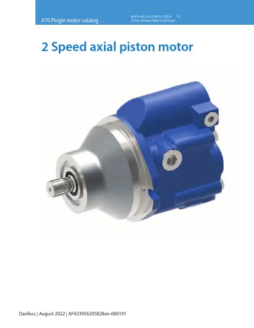
Danfoss | August 2022 | AF423956205828en-000101Table of contentsX70 PLUGIN MOTOR CATALOG2Features ......................................................................................................................03Hydraulic schematic..................................................................................................03 ............................................................................................04Model code structure................................................................................................05 ....................................................................................................06Anti-cavitation valve .................................................................................................07Brake release port......................................................................................................08Motor installation drawings .....................................................................................09Shaft installation drawing ........................................................................................10Component selection guide.....................................................................................10 ...........................................................................1232 Speed axial piston motorX70 PLUGIN MOTOR CATALOG E-MOPI-CC004-E—May 2019 FeaturesDanfoss Medium Duty Piston Motors convert hydraulic energy supplied by the pump to mechanical energy. that requires continuous rotary motion at a remote location from the power source. Axial piston motors share the design advantages of piston pumps to provide long-lasting power in a lightweight, easily serviceable package. The table below provides an overview of features. For a complete list of options, refer to the Model Code section of a given motor displacement.• Field proven rotating group design • 2 speed option• Direct hydraulic operated control • Compact design• Brake release port to use with gear box • Planetary gear box option•Hot oil shuttle & anti-cavitation check valveHydraulic schematicrelease port42 Speed axial piston motorX70 PLUGIN MOTOR CATALOG E-MOPI-CC004-E—May 2019ParameterUnitModel 374AKXXXXXA (41 cc)Model 374AKXXXXXA (49 cc)Displacementcm 3/r [in 3/r]40.6 [2.48]49.2 [3.00]Maximum displacement cm 3/r [in 3/r] 32.0 to 40.6 [1.95 to 2.48]43.3 to 49.2 [2.64 to 3.00]Minimum displacement cm 3/r [in 3/r]7.4 [0.45], 10 [0.61], 13 [ 0.79],17 [1.037], 20.5 [1.25]16.30 [0.99], 20 [1.22], 22 [1.36], 26 [1.58], 29 [1.77], 32 [1.95]Maximum rated speed at maximum displacement rpm 35003500Maximum rated speed at minimum displacement rpm45004500Nominal pressure rating *bar [psi]350 [5076]310 [4500]Peak pressure rating **bar [psi]380 [5500]345 [5000]Output torque (theoretical)N-m / bar[lbf-in/1000 psi]0.65 [394]0.79 [480]Shift pressure range bar [psi]15 - 69 [220 to 1000]15 - 69 [220 to 1000]Maximum allowable case pressure bar [psi] 3.45 [50] 3.45 [50]Viscosity - Minimum cSt 6 cSt 6 cSt Viscosity - Optimum working range cSt 10-39 cSt 10-39 cSt Viscosity - Maximum cSt 2158 cSt2158 cStMaximum Fluid Temp-Inlet °C 105 degree celcius 105 degree celcius Minimum Fluid Operating Temp °C -30 degree celcius-30 degree celciusAmbient Temperature °C -30 to 80 degree celcius -30 to 80 degree celcius Weight lbs [kg]36 lbs [16.36 kgs]36 lbs [16.36 kgs]Cleanliness21/18/13 ISO/DIS 4406 (Class 9)21/18/13 ISO/DIS 4406 (Class 9)Notes:* Nominal pressure : Max. delta system pressure at which component fatigue does not occur. (Motor life estimated by bearing life** Peak pressure : Max. operating pressure which is permissible for a short duration of time [t<1 sec]52 Speed axial piston motorX70 PLUGIN MOTOR CATALOGE-MOPI-CC004-E—May 2019Model code structure1 2 3Code title X7M X70 variable displacement piston motor4 5Displacement4140.6 cm 3/r [2.48 in 3/r] 4949.2 cm 3/r [3.00 in 3/r]6Mounting ange A Plug-in mount7 8Output shaft0115 Tooth 16/32 Spline 0213 Tooth 16/32 Spline 03Taper 1:8 Per SAE J5019Main ports sizing A M27 X 2 Metric O-Ring port (A & B)B1.0625-12 UN-2B SAE o-ring port (A & B)10Port orientation1Radial ports 2Axial ports 11Motor control options ASingle input directly operated, external control supply, without pilot valve12 Control solenoids 0None13Supply ori ce0No ori ce10.53 [0.021] ori ce 14Valving 0No valves1Shuttle valve with loop ushing 2Blocked shuttle valves3Anti cavitation valve, unidirectional LH (CCW) Rotation4Anti cavitation valve, unidirectional RH (CW) Rotation15Flushing valve pressure setting 0None110.3-12.1 bar [150-175 PSI]211.4-13.1 bar [165-190 PSI]313.8-15.9 bar [200-230 PSI]415.2-17.2 bar [220-250 PSI]520.0-21.4 bar [290-310 PSI]16 17Minimum displacements077.37 cm 3/r [0.45 in 3/r]1010.65 cm 3/r [0.65 in 3/r]1111.47 cm 3/r [0.70 in 3/r]1313.44 cm 3/r [0.82 in 3/r]1616.30 cm 3/r [1.00 in 3/r] 1717.53 cm 3/r [1.07 in 3/r] 20 20.48 cm 3/r [1.25 in 3/r] 2222.45 cm 3/r [1.37 in 3/r] 2626.85 cm 3/r [1.64 in 3/r]3232.00 cm 3/r [1.95 in 3/r]18 19Maximum displacements 00Catalogue motor displacement 3333.1 cm 3/r [2.02 in 3/r]3535.6 cm 3/r [2.17 in 3/r]3838.0 cm 3/r [2.32 in 3/r]4343.3 cm 3/r [2.64 in 3/r]4545 cm 3/r [2.75 in 3/r]4747 cm 3/r [2.87 in 3/r]20Auxiliary mounting (rear)0No auxiliary mounting21Speed sensor option0No speed sensor1Speed sensor ready (plugged port)2With speed sensor22 Shaft seal option 0Standard nitrile23 24Special features00No special features25Paint 0Do not paint (Anti rust conservation oil)1Painted primer blue (Per spec 209-13CD)2Painted primer black (Per spec 209-13B)3Green per spec 209-13K 4Grey per spec 209-13P 5Red per spec 209-13V 6Y ellow per spec 209-13BF 7Bright yellow per spec 209-13CF26 27Identi cation00Standard 28Design codeA A213X7M454967328900340067006A9A41512528A1111A23780162 Speed axial piston motorX70 PLUGIN MOTOR CATALOG E-MOPI-CC004-E—May 2019The spring centered shuttle valve, located in the motor’s end cover, moves to connect the low pressure side of the loop to the low pressure relief valve. When back pressure gets high enough the low pressure relief valve, in the end keep the transmission cool. The low pressure relief valve in the motor’s end cover typically has a lower setting than the charge pressure relief valve in the charge pump. This is soto the reservoir.72 Speed axial piston motorX70 PLUGIN MOTOR CATALOG E-MOPI-CC004-E—May 2019 Anti cavitation valveAnti-cavitation valve is to prevent the cavitation of the motor during deceleration and spin down. These are the conditions motor suction which intern reduces pressure below partial pressure and arises cavitation. By introduction of the check valve in the circuit this condition will get eliminated as itmotor at desired speed.•For this option the high pressure port needs to be de ned upfront to get the correct motor rotation. Reversing the motor is not possible with this option.release port82 Speed axial piston motorX70 PLUGIN MOTOR CATALOG E-MOPI-CC004-E—May 2019release portBrake release portX70 series plugin motors are provided with a brake release port to allow the user to make an access to the brake-release feature of the machine gear box from the rear side of the motor.A brake release port is a simple passage provided on the a rear-facing 7/16 in. SAE O-ring boss port. Refer the release port. Applications using this brake release port require an O-ring to seal the passage against the gear box.While all motors will have the brake release port, not all gearboxes are compatible with this motor feature. Get in touch with your Danfoss representative in case of queries. The rated pressure for the brake release port on the motor housing is 250 bar (this does take into account the O-ring interface between the motor and gearbox). Check your gearbox for compatibility of this feature. If found as not Leave it plugged as shown in installation drawings.92 Speed axial piston motorX70 PLUGIN MOTOR CATALOG E-MOPI-CC004-E—May 2019Motor installation drawingsMating o-ring mininstalled inside Ø4.8 [0.19]Brake release port .4375 - 20 UNF - 2B Requires an o-ring: Viton 75 Durometer cross section -2.6 ± 0.07[0.103 ± 0.003]I.D. -126.6 ± 0.8[4.987 ± 0.035][3.39]29.2102 Speed axial piston motorX70 PLUGIN MOTOR CATALOGE-MOPI-CC004-E—May 2019Shaft installation drawingsØ 24.9[.98]Component selectionThe long service life of Danfoss hydrostatic transmissions is largely dependent on the proper selection and installation of the components necessary for transmission operation. The following components are necessary for transmission operation:• Variable displacement pump• Fixed or variable displacement motor • Reservoir • Filter• Charge pump inlet line• Pump and motor case drain lines • High pressure lines • Heat exchanger• Heat exchanger bypass valve •Reservoir return lineVariable displacement pumpDanfoss hydrostatic variable displacement pumps are anaxial piston design. They are equipped with standard SAE mounts, shafts and port connections.Fixed or variable displacement motorDanfoss hydrostatic motors are an axial piston design. They are equipped with standard SAE mounts, shafts and port connections.Sizing equationsFor sizing/selecting the right pump for your application please carryout following basic calculations.Commonly Used bar 3˚Cgallons (US) kgkgf/cm 2kW liters mm N-m N-m ˚F hp inch 3lb-in lb-ft lbsVolumetric Nv =Mechanical Nm =Total Nt = Nv x NmTo Co nvert cm 3 2in 3 P nQgpm m th lb-i n th in ˚lit lb p h 112 Speed axial piston motorX70 PLUGIN MOTOR CATALOG E-MOPI-CC004-E—May 2019 ReservoirThe reservoir is an important part of the hydrostatic transmission system. It should provide adequate oil storage and allow easy oil maintenance.The reservoir must hold enough oil to provide a continuous oil supply to the charge pump inlet. It must also have enough room for the hydraulic oil to expand as the system reservoir: One half (.5) minute times (X) the maximum the reservoir. Maintaining this oil volume will give the oil a minimum of thirty (30) seconds in the reservoir. This will allow any entrained air to escape and contamination to settle out of the oil.To allow for oil expansion, the reservoir’s total volume should be at least six tenths (.6) minute times (X) the The reservoir’s internal structure should cut down turbulence and prevent oil aeration.a di user to slow the incoming oil to 1 to 1.2 meters [3-4 line should also be positioned so that returning oil enters the reservoir below the liquid surface. This will help reduce aeration and foaming of the oil.immediately reenter- ing the pump.A sixty mesh screen placed across the suction chamber of the reservoir will act as a bubble separator. The screenof the reservoir where there may be a buildup of sediment. with a screen.should be designed to minimize the possibility of There should be a drain plug at the lowest point of the reservoir and it should also have a clean-out and inspection cover so the reservoir can be thoroughly cleaned after prolonged use. A vented reservoir should have a breather Sealed reservoirs must be used at altitudes above 2500 feet. and contraction.In both cases the caps must be designed to prevent water from entering the reservoir during bad weather or machine washing.A hydrostatic transmission with a well designed reservoir will run quieter, stay cleaner and last longer.Filter should not exceed ISO 18/15 per ISO 4406. Refer to Danfoss Hydraulic Fluid Recommendations.Pressure line – 5 micrometer Suction line = 3 OR 5 micrometer enough to prevent an excessive pressure drop between the reservoir and charge pump inlet. The pressure at the charge pump inlet port must not be less than 0,80 bar absolute [6 in. Hg.] at normal continuous operating temperatures.Charge pump inlet line The inlet line to the charge pump should be large enough to keep the pressure drop between the reservoir and section. Fittings will increase the pressure drop, so their velocities below 1,25 meters [4 feet] per second. Fluid and temperature compatibility must be considered when selecting the inlet line.Pump and motor case drain The case drain lines should be large enough to limit the pump and motor case pressures (Medium Duty to 2 bar [25 PSI]) at normal operating temperatures. Fluid and temperature compatibility must also be considered when selecting the case drain lines.High pressure lines The high pressure lines that connect the pump and motor must be able to withstand the pressures generated in the high pressure loop.Heat exchanger Use of a heat exchanger is dependent on the transmission’s duty cycle and on machine layout. The normal continuous motor cases should not exceed 80°C [180°F] for most exceed 107°C [225°F].The heat exchanger should be sized to dissipate 25% of the maximum input power available to the transmission. It must also be sized to prevent the case pressures in the pump and motor from getting too high. Medium duty case pressure up to 2 bar [25 psi], at normal operating temperatures, are acceptable.122 Speed axial piston motorX70 PLUGIN MOTOR CATALOG E-MOPI-CC004-E—May 2019Heat exchanger bypass valve The heat exchanger bypass valve is a pressure and/or temperature valve in parallel with the heat exchanger. Its purpose is to prevent case pressures from getting too high. The heat exchanger bypass valve opens when the oil is thick, especially during cold starts.Reservoir return line The same general requirements that apply to case drain lines apply to the reservoir return line.Bearing life estimation revolutions or time until a fatigue failure. Bearing load is calculated as a reaction which is derived from the moment created by the piston side load. Magnitude of the side load directly related to the speed and pressure at which a unit can be operated.Bearing life is a function of the side loads coming on the and cleanliness also a ects the life of bearing.If detail bearing life analysis is required, you can contact a Danfoss representative.Installation requirements The mounting orientation of pumps and motors is unrestricted provided the case drain of the pump and motor remain full. Position the case drain such that it assures an oil level at or above unit center line at start-up. The case drain be connected to the highest drain port on each of the units. This assures that the pump and motor cases remain full.The combined torque required to turn two or more pumps must not exceed the torque rating of the input drive shaft of the front piston pump. Installer to provide centering and a secure neutral for pump swashplate control shaft. An external support is recommended for all tandems.Open loop circuits Danfoss pumps and motors may be used in open loop circuits under certain operating conditions. Consult your Danfoss representative for details.Introduction system. Proper selection of oil assures satisfactory life and operation of system components. The purpose of this section is to provide readers with the knowledge required to Danfoss hydraulic components Viscosity and temperature most important characteristics to consider when choosing to maintain proper sealing at the operating temperatures of the hydraulic system.For viscosity requirements, see table operating temperatures of the hydraulic system. A high temperature.Lubricants used for hydraulic applications may contain shearing of VI improvers used in the formulations.Anti-wear hydraulic oils containing polymeric thickeners, viscosity index improvers (VII) are generally used for wide experience temporary and permanent viscosity loss during use in hydraulic system. Check the extent of viscosity loss (shear stability) to avoid hydraulic service below the recommended minimum viscosity. Oil with good shear stability is recommended for wide band temperature applications. Multi-grade engine oils, ATFs, UTTOs, etc., also contain VIIs, and viscosity loss will be encountered during use.Cleanliness important. More than 70% of all failures are caused by contamination. Danfoss recommends that the uid used in its hydraulic components be maintained per ISO 4406. Cleanliness level requirements vary with the hydraulic components. The cleanliness of a hydraulic system is dictated by the cleanliness requirements of the most stringent component in the system. in the table.OEM’s and distributors who use Danfoss hydraulic components in their hydraulic systems should provide these requirements in their designs.Contact Danfoss lter representative for ltration information.132 Speed axial piston motorX70 PLUGIN MOTOR CATALOG E-MOPI-CC004-E—May 2019 Fluid maintenance performance and reliability of the system. Maintaining and additive level is essential for excellent hydraulic system is recommended.Fluid selection Premium grade anti-wear (AW) petroleum based hydraulic uids will provide the best performance with Danfoss hydraulic components. Fluids that meet Danfoss Hydraulic Fluid Seeci cation E-FDGN-TB002-E are considered good quality anti-wear hydraulic uids. These uids pass Danfoss Vickers* 35VQ25A high pressure vane pump test (Eaton ATS-373 test procedure, ASTM D 6973).Automotive crank case oils with American Petroleum Institute (API) letter designation SF, SG, SH, SJ, or higher per SAE J 183 classes of oils are recommended for applications using Danfoss DG valves Automotive crankcase oils generally exhibit less shear stability compared to higher loss of viscosity during service life.Other mineral oil based lubricants commonly used in and universal tractor transmission oils (UTTO).biodegradability etc., are necessary for the application. Additional notes in the system must be considered. Viscosity limitations have to meet the most stringent component requirements.target one ISO code cleaner for each particle size, than that reading when the system is cold.For more details, refer to Danfoss Fluid Recommendation Document # 03-401-2010.Contact your representative if you have speci c questions about the uid requirements of Danfoss hydraulic components Viscosity & cleanliness recommendation Product Minimum*Optimum Maximum ISO Cleanliness Medium duty piston pumps and motors charged systems 6.0 cSt (45 SUS)10 – 39 cSt (60-180 SUS)2158 cSt (10000 SUS)21/18/13ote:N *Minimum viscosit y applies at intermittent condition of 10% of every minute. At viscosities lower than 70 sus, additional antiwear additives must be added to prevent premature wear. Please referto Danfoss document 03-401 for further details.Additional notes:• Fluids too thick to ow in cold weather start-ups will cause pump cavitation and possible damage. Motor cavitation is not a problem during cold start-ups, except for two speed motors. Thick oil can cause high case pressures which in turn cause shaft seal problems.• When choosing a hydraulic uid, all the components in the system must be considered and the optimum viscosity range adjusted accordingly. For example, when a medium duty piston pump is combined with a Disk Valve Motor the optimum viscosity range becomes100 - 180 SUS [20 - 39 cSt] and viscosity should never fall below 70 SUS [13 cSt].• If the natural color of the uid has become black it is possible that an overheating problem exists.• If the uid becomes milky, water contaminationmay be a problem.• Take uid level reading when the system is cold.• Contact your Danfoss representative if you havespeci c questions about the uid requirements of Danfoss hydraulic components.。
assoma磁力泵
assoma磁力泵
assoma磁力泵驱动无轴封泵浦 **8226; 提供插管、由任、法兰各种配管方式,方便客户选择。
**8226; 配合耐蚀环氧树脂涂装隻金属托架及不锈钢脚架,可充分支撑泵浦及配管之负载。
**8226; 配备IEC标准马达:IP54或55 防护等级、F级绝缘。
**8226; 接液部材质皆为耐蚀性强之工程塑胶,依输送液腐蚀性强弱可选择PP+GF或PVDF材质。
**8226; 构造简单,维修、保养容易。
assoma磁力泵接液部材质 泵浦本体 PP / PPG / PVDF+CF 轴心 995 CERAMIC 轴承 CARBON / RULON / SSiC 密封件 EPDM / VITON 符合ISO2858、2084、3661及5199的设计标准。
**8226; 球状石墨铸铁泵壳内衬碳纤维强化ETFE氟素塑酯,结构性耐蚀性优异。
**8226; 磁偶合器采用稀土类强力磁铁,能提供高扭矩及重负荷启动不打滑的能力。
assoma 磁力泵规格性能表 型式 口径 (mm) 额定流量 (l/min) 额定扬程 (m) 马达出力 (kW) 极数使用液体 温度范围 入口 出口 50Hz 60Hz 50Hz 60Hz AMA-CT 50 40 300 300 49.8 56.3
5.5/7.5 2 5~90oC AMA-DT 65 40 400 400 50.9 72.5 11/15/18.5 2 5~90 oC AMA-EP 65 50 500 500 32.4 37.6 5.5/7.5 2 5~90 oC AMA-FP 80 65 1000 1000 34.5 51.3 11/15/18.5 2 5~90 oC。
HYDRAULICGEARPUMPSANDMOTORS液压齿轮泵-Casappa
()
D-H-C D
ISO/DIN
() N = 丁氰橡胶 N (标准) - V= 氟橡胶
() 轴封能承受的最大压力和安装组合 D
带刮油密封环的标准轴封 最大 3 bar 单向泵
H
高压专用轴封 最大 25 bar
C
带刮油密封环的高压专用轴封 最大 25 bar
最大 3 bar 单向马达 双旋向泵和马达
500 500 500 500 500 500 500
表中各值为单向泵和马达的值。 双旋向泵和双向马达最大压力比表中值低15%。 欲知不同工况下的更多信息,请咨询我们的销售部门。
DCAT034-001
ID03
3
Polaris PH
GENERAL DATA PUMPS AND MOTORS 泵和马达的通用数据
01/12.2014
7
6
5
ቤተ መጻሕፍቲ ባይዱ
DCAT034-001
ID03
1
Polaris PH
FEATURES 产品特性
结构 安装 管接口 旋向(正对传动轴方向) 进油口压力范围 单旋向马达和双旋向内部泄油马达最大背压 双旋向马达最大泄油压力 此系列马达最大背压(外泄双向马达) 液压油温度范围 液压油 黏度范围 过滤要求 3段式结构重载外啮合齿轮泵及马达 欧标-SAE-德标法兰 螺纹直通端口或法兰端口 逆时针(S) -顺时针(D) -双旋向外泄(L - R)-双旋向内泻(B) 10 ÷ 44 psi [0,7 ÷ 3 bar (abs.)] p1 (连续工作压力) 最大 73 psi (5 bar) # p2 ( 20 秒以内) 最大 116 psi (8 bar) # p3 ( 8 秒以内) 最大 218 psi (15 bar) # 73 psi (5 bar) # 2175 psi (150 bar) 见表(1) 符合ISO/DIN标准的矿物油基液压油。 欲知其他液压油信息,请咨询我们的技术销售部门。 建议值:从60 到456 SSU [12 到 100 mm2/s (cSt)] 最高允许值:3410 SSU [750 mm2/s (cSt)] 见第3页表(2)
齿轮油泵毕业设计
齿轮油泵毕业设计宣城职业技术学院毕业设计齿轮油泵———基于Pro/E的齿轮油泵的设计倪欢班级 10数控专业数控技术学号 201051052教学系汽车工程系指导老师赵庆荣完成时间 2012 年 10 月 15 日至 2013 年 6 月 15 日目录一、前言...................................................................... ............................................. 2 二、齿轮油泵Pro/ENGINEER 总装造型......................................................................3 三、其他零件Pro/ENGINEER造型设计.......................................................................5 (一)齿轮的计算...................................................................... ............................... 5 (二)参数的设置..................................................................................................... 5 四、齿轮油泵各组成零件的选材分析 ......................................................................12 (一)材料的选择原则 ..................................................................... ...................... 12 (二)材料的选择方法 ..................................................................... ...................... 12 五、产品重要零件AutoCAD绘图 ..................................................................... ........ 15 (一)零件视图的选择 ..................................................................... ........................... 16 (二)主动轴的尺寸分析 ..................................................................... ...................... 16 (三)表面粗糙度的选定 ..................................................................... ................... 16 (四)公差与配合的选择 ..................................................................... ................... 17 六、齿轮油泵装配图 ..................................................................... .......................... 22 (一)装配图的内容 ..................................................................... .......................... 22 (二)画装配图的一般步骤 ..................................................................... ............... 23 (三)装配图的尺寸标注 ........................................................................................ 23 (四)测绘总结 ..................................................................... ................................. 23 七、齿轮油泵故障举例 ..................................................................... ...................... 23 (一)油泵内部零件磨损 ..................................................................... ................... 23 (二)油泵壳体的磨损 ..................................................................... ...................... 24 (三)油封磨损,胶封老化 ..................................................................... ............... 24 (四)机油泵供油量不足或无油压 ..................................................................... ..... 24 八、齿轮油泵的维修 ..................................................................... .......................... 24 (一)主动轴与衬套磨损后的修复 ..................................................................... ..... 24 (二)润滑油泵壳体的修理壳体裂纹的修理 ............................................................ 25 (三)主动轴衬套孔与从动轴孔磨损的修理 ............................................................ 25 (四)泵壳内腔的修理 ..................................................................... ...................... 25 (五)泵盖的修理................................................................................................... 25 设计小结...................................................................... ........................................... 26 致谢...................................................................... .................................................. 27 参考文献: .................................................................... .. (27)1基于Pro/E的齿轮油泵的设计摘要:本课题是依据齿轮油泵的装配图为基础进行完善设计,应用PRO/E4.0进行了总体造型和部分零件的造型测绘及分析,以及使用Autocad2007进行了两个重要齿轮油泵组成零件的绘制,完成了齿轮油泵重要零件的设计,绘制出齿轮油泵的零件图。
AMESim_Solution_for_工程机械
成功案例
Bosch-Rexroth 负载感应 / 阀 静液传动 AMESim 是 Robert Bosch 集团的通用软件平台
静液传动 传动链 轮胎 车体
成功案例
Bosch-Rexroth
完整的车辆分析 和ADAMS的接口
成功案例
Hytos 液压阀制造商 需要液压和机构集成的系统方法
Pressure
0
45
90
135
180
225
270
315
360
0
45
90
135
180
225
270
315
360
Shaft angular displacement [癩
Shaft angular displacement [癩
Flow ripple
Optimized pump
Pump delivery pressure
成功案例:
Doosan 轮式装载机转向系统优化
Steering Cylinder Cushion Valve
8 Q
Flow Amplifier Steering Pump
Q
Steeri ng Unit
Slow Steering(20rpm)
Fast Steering(70rpm)
成功案例
CFD工具的接口
零件,滑阀的位置和速度
CFD
Fluent, StarCD, CFX…
系统模型
作用在运动体上的力
合作方 软件
完整系统 多领域相互作用 边界条件
局部的详细几何3D分析
工程机械的控制:SIMULINK的接口
AMESim
意大利CASAPPA(凯斯帕)股份公司 PLD 铝合金同步器选型样本
Gear flow dividersPLD 02TAE d i t i o n :02/11.2000R e p l a c e s :P L D 01TA -01/02.2000l Modular design l Accurate division of flow l Compact overall dimension l Built-in relief valve2004D024-004Po l a risGENERAL FEATURESMo d ern ma c hi n ery with in c re a s ingly com p lex cir c u i ts of t en ne e ds com b i n a t ions of se p a r a t e and in d e p en d ent move m ents. PO L ARIS 10 and POLARIS 20 flow di v i d ers pro v i d e tec h ni c ally ad v an c ed, low cost po w er tran -smis s ion a nd s ol v e a p p li c a t ion p ro b lems w he r e v er h ydra u l ic f low h as d i v i d ed. I n l ine w ith o ur p o l icy o f s im p lif y ing the d e s ign o f h ydra u l ic c ir c u i ts, o ur f low d i v i d ers h ave r e l ief v al v es b u i lt i n t o l i m it p res s u r e a nd p re v ent c a v i t a t ion.The s e c om p o n ents p er m it h ydra u l ic c ir c u i ts t o b e c le v erly o p t i m i s ed a nd r e d u c e i n s ta l la tion costs. The POLARIS flow d i v i d ers a re t wo o r m ore s ec t ion d i v i d ers w ith a c om m on i n t er n al c on n ec t ing s haft. T his m a i n t a i ns a c on s tantra t io b et w e e n t he f lows t hro u gh e ach s ec t ion i n a c c or d an c e w ith s ec t ion d is p lace m ent. T he o r et i c al w or k ing o f r o -tary flow di vi ders do not dis si pa te energy in fact if the out let pres su re of one sec tion drops b e l ow i n p ut p res s u r e,that sec tion ope ra tes as a mo tor and ta kes energy from the flu id. This energy is not wa sted b ut tran sfer red by the com m on shaft to the ot h er sec t ions which ope r a t e as pumps and the r e f o r e need out l et pres s u r e to be gre a t erthan in l et pres s u r e. In wor k ing conditions, over a ll ef f i c ien c ies de p end on the sum of the sin g le sec t ions ef f i -ciency. These products can the r e f o r e be used as flow equal i z e rs, flow di v id e rs and pres s ure in t en s i f i e rs as shown in the ta b le be l ow.Flu i dMi n e r al oil ba s ed hydra u l ic flu i ds to DIN 51524.For ot h er flu i ds ple a s e con s ult our sa l es de p ar t ment.Flu i d tem p e r a t u r e ran g e[°F]-13 to +176 with Buna N se a ls -13 to +230 with Vi t on V se a ls Flu i d vi s co s ity ran g e[SSU]55 to 455 re c om m en d edUp to 3409 per m it t edFil t e r ing requirement∆p > 3000 psi∆p < 3000 psiCon t a m i n a t ion class NAS 1638810Con t a m i n a t ion class ISO 440617/1419/16Achie v ed with fil t er βx= 7510 µm25 µmOut l et pre s sureSections with same di s pla c e m entSec t ions withdif f e r ent di s pla c e m entSame Flow equa l izers Flow di v i d ers DifferentFlow equa l i z ersFlow di v i d ersPres s u r e in t en s i f iersD024-*******Po l a ris4004D024-004Po l a risTypeDi s pla c e m entMax. out l et pres s u r e Max. out l et ∆p bet w e e n sec t ions (1)Spe e d Flow per section p 1p 2min.max.min.max.cu in/rev psipsi min -1U S gpm PLD 10•20.12360040003000125042000.70 2.35PLD 10•3,150.1936004000300012053990 1.05 3.49PLD 10•40.2436004000300011753840 1.32 4.28PLD 10•50.3036004000300011403680 1.60 5.15PLD 10•6,30.3836004000300011003500 1.936.13MAX. FLOW FOR INLET SECTION9.25 US gpmGENERAL DATAPLD 10p 2= Max. peak pressurep 1= Max. con t i n u o u s pressure (1): Pres s u r e in t en s i f iers can work at hi g her pres su re bet w e e n sec t ions.For wor k ing con d i t ions out s i d e the re c om m en d ed li mits shown in the ta b le, ple a s e con s ult our sa l es de p ar t ment.D024-*******Po l a risTypeDi s pla c e m entMax. out l et pressure Max. out l et ∆p bet w e e n sec t ions (1)Spe e d Flow per sec t ion p 1p 2min.max.min.max.cu in/rev psipsi min -1US gpm PLD 20•40.2936004000300012504100 1.63 5.34PLD 20•6,30.3936004000300012353970 2.15 6.90PLD 20•80.5036004000300012203850 2.668.36PLD 20•11,20.6736004000300012003660 3.5510.79PLD 20•140.8736004000300011753460 4.5013.22PLD 20•16 1.0130003300300011603335 5.1414.76PLD 20•20 1.2730003300300011303125 6.3017.36PLD 20•25 1.58300033003000110029007.6420.13PLD 20•31,51.99300033003000106026609.2023.09MAX. FLOW21.14 US gpmp 2= Max. peak pres s u r ep 1= Max. con t i n u o u s pres s u r e (1): Pres s u r e in t en s i f iers can work at hi g her pres s u r e bet w e e n sec t ions.For wor k ing con d i t ions out s i d e the re c om m en d ed li m its shown in the ta b le, ple a s e con s ult our sa l es de p ar t ment.GENERAL DATAPLD 206004D024-004Po l a risD024-0040047Po l a ris8004D024-004Po l a risD024-0040049Po l a ris10004D024-004Po l a risD024-********12004D024-004D024-********14004D024-004D024-********16004D024-004D024-********18004D024-004D024-********1SeriesCODE Pol a r is 10PLD 10Po l a r is 20PLD 202Num b er of sec t ionsCODE From 2 to 6 sec t ions2 ... 63Stan d ard side in l et sectionCODE Left in l et section (1)CS4Inlet port dimen s ionsCODEBRITISH STANDARD PIPE PARALLEL (BSPP)PLD 10GD PLD 20GESAE STRAIGHT THREAD PORTS (ODT)PLD 10OB PLD 20OD5DisplacementCODEcu in/revPo l a r is 100.12PLD 10-20.19PLD 10-3,150.24PLD 10-40.30PLD 10-50.38PLD 10-6,3Po l a r is 200.29PLD 20-40.39PLD 20-6,30.50PLD 20-80.67PLD 20-11,20.87PLD 20-141.01PLD 20-161.27PLD 20-201.58PLD 20-251.99PLD 20-31,5CASAPPA S.p.A. - Par m a - Italy - Tel.: (+ 39) 0521 304111 - Fax: (+ 39) 0521 804600CASAPPA Corp. - Ba t a v ia, IL 60510 U.S.A. - Pho n e: 630 761-0041 - Fax: 630 761-0048CASAPPA GmbH - Stut t gart - Ger m any - Tel.: + 49 711 7811770 - Fax: + 49 711 7811771CASAPPA SARL - Jan n ey r ias - Fran c e - Tel.: + 33 4 72462112 - Fax: + 33 4 72462100http://www.ca s ap p - e-mail: info@ca s ap p CODEOut l et port di m en s ions6BRITISH STANDARD PIPE PARALLEL (BSPP)G C PLD 10G DPLD 20SAE STRAIGHT THREAD PORTS (ODT)O APLD 10O C PLD 20CODEIntermediate in l et sec t ion (2)7CI Inter m e d ia t e in l et sec t ionCODE Sup p le m en t ary in l et sec t ion (2)8CD Right in l et sec t ion (1)CODE Re l ief alve9VPEF Re l ief alveCODEVal v e set t ing [bar]10....See page 3CODET Out l et port di m en s ions11BRITISH STANDARD PIPE PARALLEL (BSPP)G C PLD 10G DPLD 20SAE STRAIGHT THREAD PORTS (ODT)O APLD 10O B PLD 20CODE Seals 12....Buna (3)VViton(1) Lo o k ing at the sec t ions from the out l et ports side .(2) Cho i c e the in l et sec t ions num b er ac c or d ing to the ge n e r al data on page 4 and 5.(3) Omit this code for Buna se a ls.PLD 20/3/CS -GE /25-GD /25-GD /CI -GE /25-GD /CD -GE /VPEF -50-GD -VSe r ies/Left in l et sec t ion/Sec t ion/Sec t ion/Interm. i n -let sec t ion /Sec t ion/Right in l etsec t ion/Re l ief val v e123456567456849101112Only for ver s ionwith val ve。
桑德皮珀泵 250至600 gpm 手册说明书
S A N D P I P E R P U M P.C O MWarren Rupp, Inc. • A Unit of IDEX Corporation 800 N. Main St., Mansfield, Ohio 44902 USA Telephone 419.524.8388 • Fax 419.522.78675 YEAR LIMITED PRODUCT WARRANTY5 Year Guarantee for defects in material or workmanship. See /content/warranty-certificationsfor complete warranty, including terms and conditions, limitations and E ONLY GENUINE SANDPIPER PARTS All certification, standards, guarantees & warrantiesoriginally supplied with this pump will be invalidated by the use of service parts not identified as “Genuine SANDPIPER Parts.”CAPACITY GPMLPM2503003504004505000P S IAIR CONSUMPTION IN SCFMAIR PRESSURE IN PSI200150100501400153045607590105120135150165550B A R 891060010(17)1• No-lube, no-stall designSOLIDS-HANDLING• Up to .25 in. (6.3mm)HDB1½ / HDB40 METALLIC BALL VALVE PUMP ISO 9001 Certified I SO 14001 CertifiedII IIWEIGHTS• Aluminum 75 lbs. (34kg)• Cast Iron 104 lbs. (47kg)• Stainless Steel 107 lbs. (48kg)S A N D P I P E R P U M P.C O MWarren Rupp, Inc. • A Unit of IDEX Corporation 800 N. Main St., Mansfield, Ohio 44902 USA Telephone 419.524.8388 • Fax 419.522.7867DIMENSIONSHDB1 1/2 & HDB40, Side PortedDimensions are ± .13" (3mm). Figures in parenthesis = millimeters15.503949.962532.235713.88352.19510.63270DISCHARGE PORT1 1/2" NPT [1 1/2" BSP TAPERED]SUCTION PORT1 1/2" NPT [1 1/2" BSP TAPERED]9.152328.712216.8117311.002791.1830VERTICAL SUCTION12.06306VERTICAL DISCHARGE14.843777.67195AIR INLET 3/4" NPT8.632199.002294.501144.321104X .47 [12] MOUNTING HOLESAIR EXHAUST 1" NPTHDB1 1/2 & HDB40, Down PortedDimensions are ± .13" (3mm). Figures in parenthesis = millimeters15.814026.271599.9625323.3259210.64270 DISCHARGE PORT1 1/2" NPT [1 1/2" BSP TAPERED]SUCTION PORT1 1/2" NPT [1 1/2" BSP TAPERED]14.5036811.5929412.04306 16.26413.18517.28439VERTICAL DISCHARGE5.22132VERTICAL SUCTION17.7245010.55268VERTICAL PORTINGAIR INLET 3/4" NPT12.5031710.50267 8.6421914.5036810.642708X .44 [11]MOUNTING HOLESS A N D P I P E R P U M P.C O M Warren Rupp, Inc. • A Unit of IDEX Corporation 800 N. Main St., Mansfield, Ohio 44902 USA Telephone 419.524.8388 • Fax 419.522.7867Material Profile:Operating Temperatures:Max.Min.CONDUCTIVE ACETAL: Tough, impact resistant, ductile. Good abrasion resistance and low friction surface. Generally inert, with good chemical resistance except for strong acids and oxidizing agents.190°F 88°C-20°F -29°CEPDM: Shows very good water and chemical resistance. Has poor resistance to oils and solvents, but is fair in ketones and alcohols.280°F 138°C -40°F -40°C F KM (FLUOROCARBON): Shows good resistance to a wide range of oils and solvents; especially all aliphatic, aromatic and halogenated hydrocarbons, acids, animal and vegetable oils. Hot water or hot aqueous solutions (over 70°F(21°C)) will attack FKM.350°F 177°C-40°F -40°CHYTREL ®: Good on acids, bases, amines and glycols at room temperatures only.220°F 104°C -20°F -29°C NEOPRENE: All purpose. Resistance to vegetable oils. Gener-ally not affected by moderate chemicals, fats, greases and many oils and solvents. Generally attacked by strong oxidizing acids, ketones, esters and nitro hydrocarbons and chlorinated aromatic hydrocarbons.200°F 93°C-10°F -23°CNITRILE: General purpose, oil-resistant. Shows good solvent, oil, water and hydraulic fluid resistance. Should not be used with highly polar solvents like acetone and MEK, ozone, chlorinated hydrocarbons and nitro hydrocarbons.190°F 88°C -10°F -23°CNYLON: 6/6 High strength and toughness over a wide tem-perature range. Moderate to good resistance to fuels, oils and chemicals.180°F 82°C 32°F 0°CPOLYPROPYLENE: A thermoplastic polymer. Moderate tensile and flex strength. Resists stong acids and alkali. Attacked by chlorine, fuming nitric acid and other strong oxidizing agents.180°F 82°C 32°F 0°C PVDF: (Polyvinylidene Fluoride) A durable fluoroplastic with excellent chemical resistance. Excellent for UV applications. High tensile strength and impact resistance.250°F 121°C 0°F -18°C SANTOPRENE ®: Injection molded thermoplastic elastomer with no fabric layer. Long mechanical flex life. Excellent abrasion resistance.275°F 135°C -40°F -40°C UHMW PE: A thermoplastic that is highly resistant to a broad range of chemicals. Exhibits outstanding abrasion and impact resistance, along with environmental stress-cracking resistance.180°F 82°C -35°F -37°C URETHANE: Shows good resistance to abrasives. Has poor resistance to most solvents and oils.150°F 66°C 32°F 0°C VIRGIN PTFE: (PFA/TFE) Chemically inert, virtually impervious. Very few chemicals are known to chemically react with PTFE; molten alkali metals, turbulent liquid or gaseous fluorine and a few fluoro-chemicals such as chlorine trifluoride or oxygen difluoride which readily liberate free fluorine at elevated temperatures.220°F 104°C-35°F -37°CMaximum and Minimum Temperatures are the limits for which these materials can be operated. Temperatures coupled with pressure affect the longevity of diaphragm pump components. Maximum life should not be expected at the extreme limits of the temperature ranges.Metals:ALLOY C: Equal to ASTM494 CW-12M-1 specification for nickel and nickel alloy.STAINLESS STEEL: Equal to or exceeding ASTM specification A743 CF-8M for corro-sion resistant iron chromium, iron chromium nickel and nickel based alloy castings for general applications. Commonly referred to as 316 Stainless Steel in the pump industry.For specific applications, always consult the Chemical Resistance Chart.CAUTION! Operating temperature limitations are as follows:EXPLANATION OF PUMP NOMENCLATUREPUMP SERIESHD Heavy DutyPUMP DESIGNBSolid BallPUMP SIZE & OPTIONS1 1/2”P1 Intrinsically Safe ATEX Compliant Pulse OutputSB S tainleSS -B raSS Sleeve and Spool Set DISCHARGE PORTING POSITIOND Down Ported S SideDIAPHRAGM CHECK VALVE MATERIALSB NitrileCFKM with PTFEMATERIALSF FDA Accepted White NitrileGN Neoprene Backup with PTFE Overlay and PTFE Check Balls GR Hytrel Backup w/ PTFE Overlay/PTFE Balls GZ PTFE/Nitrile Bonded One-Piece/PTFE Balls H EPDM with PTFE I EPDM N Neoprene R HytrelS SantopreneU Santoprene with PTFE V FKMDESIGN LEVEL7CONSTRUCTIONA Aluminum Wetted, Aluminum AirCI Cast Iron Wetted, Aluminum Air II Cast Iron Wetted, Cast Iron AirSI Stainless Steel Wetted, Cast Iron Air SS Stainless Steel Wetted, Aluminum Air HC Alloy-C Wetted, Aluminum Air HIAlloy-C Wetted, Cast Iron AirNOTE: See service manual for ATEX details.SP_DS_TemplateDataSheet_0118____ _____ __ ___ __ __Pump Pump Pump Size Discharge Diaphragm/ Design ConstructionSeriesDesignand Options Porting Valve LevelHD X XXXXXX, XX XXX X XXModel #:(fill in from pump nameplate)Your Model #:HD II 2II 2。
工控产品品牌大全
ABB 伺服电机AC TECH 变频器, 驱动器Advance Motion Controls 伺服控制器AXOR 伺服电机, 控制器AMK 伺服电机, 控制器ANIMATICS 伺服电机, 控制器ARNOLD MULLER 伺服电机, 控制器AEG 伺服电机, 控制器Andrive 伺服电机, 控制器BALDOR 伺服电机, 控制器BAUMULLER 伺服电机, 控制器BAUTZ 伺服电机, 控制器Bardac 伺服电机, 控制器CEM 伺服电机, 控制器CMC 伺服电机, 控制器Copley 伺服电机, 控制器CSR 伺服电机, 控制器DIERKING 伺服电机, 测速电机DriveTech 伺服电机, 控制器Drive Systems 伺服电机EAT 伺服电机, 控制器ELAU 伺服电机, 控制器Electrocraft 伺服电机, 控制器E.C.S 伺服电机, 控制器Elmo 伺服电机, 控制器EMOD 伺服电机Engel Hardt 伺服电机, 控制器EPH 伺服电机, 控制器Ferrocontrol 伺服电机, 控制器GALIL 伺服电机, 控制器GEC ALSTHOM 伺服电机, 控制器GEORGII KOBOLD 伺服电机, 控制器Giddings & Lewis 伺服电机及控制器Gould 伺服电机, 控制器Gettys 伺服电机, 控制器IIS 伺服电机, 控制器ID 伺服电机, 控制器HAUSER 伺服电机, 控制器HDD 伺服电机, 控制器HEYNAU 伺服控制器Hardmeier 伺服电机, 控制器Indramat 伺服电机, 控制器Inland 伺服电机, 控制器Infranor 伺服电机, 控制器IRT 伺服电机, 控制器ISOFLUX 伺服电机, 控制器Jetter 伺服电机, 控制器JVL 伺服电机, 控制器JUNG 伺服电机, 控制器KB 电机控制器Kollmorgen 伺服电机, 控制器Lenze 伺服电机, 控制器LEAG 伺服电机, 控制器LUST 伺服电机, 控制器MAGNETIC 伺服电机, 控制器Mayr 伺服电机, 控制器MA VILOR 伺服电机MCG 伺服电机, 编码器NUM 伺服电机, 控制器OSW ALD 伺服电机, 控制器PARVEX 伺服电机, 控制器PEERLESS-WINSMITH 伺服电机, 控制器POWERTEC 伺服电机, 控制器ProControl 伺服电机, 控制器SAD 伺服电机, 控制器SBC 伺服电机, 控制器Seidel 伺服电机, 控制器SELCA 伺服电机, 控制器SEM 伺服电机, 控制器SERV AX 伺服电机, 控制器Servomac 伺服电机, 控制器Selema 伺服电机, 控制器SIEMENS 伺服电机, 控制器SMB 伺服电机, 控制器SSB 伺服电机, 控制器Stromag 伺服电机, 控制器Systec 伺服电机, 控制器Slo-Syn 伺服电机, 控制器Superior Electric 伺服电机, 控制器TDE MACNO 伺服电机, 控制器VICKERS 伺服电机, 控制器Warner Swasey 伺服电机, 控制器Winkelmann 伺服电机, 及控制器编码器:Anilam 编码器ASM 编码器Avtron 编码器Baumer 编码器Carlen 编码器Clifton 编码器COPI 编码器DRC 编码器DEUTSCHMANN 编码器,凸轮控制器DUNCAN 编码器ELAP 编码器ELGO 编码器Eltra 编码器EMETA 编码器EPC 编码器ESTERS 编码器EUCHNER 编码器FRABA 编码器FSG 编码器FSI 编码器Fork 编码器Gaebridge 编码器Givi Misure 编码器GURLEY 编码器HAROWE 编码器HENGSTLER 编码器HEIDENHAIN 编码器HUBNER 编码器Hohner 编码器IHI 编码器IMG 编码器INDUCODER 编码器Industrial Encoder 编码器IDEACOD 编码器Jahannes Hubner 编码器JENA 编码器Kubler 编码器KEP 编码器Lenord+Bauer 编码器Leine & Linde 编码器Lake Shore 编码器LIKA 编码器Litton 编码器LTN 编码器Micronor 编码器MTL 编码器Photocraft 编码器Quantum 编码器Red Lion 编码器RENCO 编码器RSF 编码器SAIET 编码器Solartron 编码器SCANCON 编码器SELET 编码器STEGMANN 编码器SUMTAK 编码器SIKO 编码器SERVOTECHNIK 编码器STROTER 编码器TEKEL 编码器THALHEIM 编码器, 测速电机Torque Systems 编码器TR 编码器T+R 编码器TWK 编码器US DIGITAL 编码器W+S 编码器WACHENDORFF 编码器测速电机:Baumuller 测速电机EW HOF 测速电机HORN 测速电机NORIS 测速电机Servo-Tek 测速电机Thalheim 测速电机液压,气动元件大全ACL 电磁阀Airpot 气缸AIRTEC 气动元件ALCON 电磁阀ARGUS 液压元件ARO 气动元件ARON 液压元件ASK 液压元件及仪表BERARMA 叶片泵BIERI 液压元件Boll & Kirch 过滤器BUCHER 液压元件CASAPPA 液压元件CHAR-L YNN 液压马达CONTINENTAL 液压元件CONCORDIA 气动元件CPOAC 气动元件DAIKIN 液压元件DELTROL 液压元件Dynamco 电磁阀EDI 液压元件EMG 伺服阀EPE 过滤器EUGEN SEITZ 电磁阀FABCO-AIR 气动元件FLUTEC 液压元件FUJI ENGINEERING 电磁阀FUJIKIN 电磁阀GPA 电磁阀HPI 液压元件HYDROTECHNIC 液压元件HYDRONORMA 电磁阀HYDROTECHNIK 液压元件HYDROPA 液压元件HTF 液压元件ITAYA 公司齿轮泵Integrated Hydraulics 液压元件KANEKO 电磁阀konan 气动元件KEIHIN 电磁阀KV 电磁阀LUCIFER 电磁阀MARZOCCHI 泵,马达MAAG 油泵MAC 电磁阀MAGNET SCHULTZ 电磁阀Micro Precision 液压马达NIPPON OIL PUMP (NOP) 油泵NIPPON GEROTOR CO., LTD 公司油泵NKE 气缸, 气动手指NOK 气动元件Peter Paul 电磁阀Phd 油缸RACINE 油泵RICKMEIER 泵阀ROSS 电磁阀SC HYDRAULIC ENGINEERING 气动马达SCEM 电磁阀Schrader Bellows 气动元件Skinner 电磁阀Sterling 液压元件STORZ 油缸STUCCHI 单向阀SUN 液压元件SUMITOMO 齿轮泵TOGNELLA 液压元件TACO 气动元件Trochoid 油泵UCC 过滤器VERSA 电磁阀V & B SERVOCOMANDI 液压气动元件V on Ruden 液压马达, 齿轮头WEKUPO 柱塞泵Walther 快速接头WAIRCOM 气动元件Wilkeson 气动元件WSI 液压马达, 齿轮箱工业电气,传感器大全AECO 接近开关ACi 工业开关, 传感器Acromag 自动化产品ACU-RITE 自动化产品ACS 传感器, 自动化元件AEP 压力开关, 压力变送器ALLEMANO 压力仪表ALTHEN 传感器ALTMANN 电位计American Sensors 传感器ANILAM 自动化产品ANTUNES 压力开关AROMANIKKI 流量开关ASAHI 自动化仪表ASI 接近开关等自动化元件ASO 安全自动化元件ASTECH 传感器atc 自动化元件atr 自动化元件ATHENA 温控器AUTOTRON 传感器AUTOTECH 自动化元件BARKSDALE 压力, 温度仪表BACO 安全自动化产品BECKHOFF 自动化产品BENDER 自动化产品BENEDIKT 开关BERNSTEIN 传感器BETA 传感器Binding Union 公司过程控制仪表BIRCHER 安全自动化产品BRAUN 速度仪表BRODERSEN 继电器BROSA 力传感器BROSE 自动化显示仪表, 电源BROYCE CONTROL 控制继电器, 计时器BST 控制产品BTI 安全开关BTR 工业继电器BUHLER 液位开关Cabur 自动化元件CAL 温控器CANAAN 计时器CAPTRON 传感器CAREL 温度仪表CDC 自动化元件CEDES 传感器Celduc 自动化产品CEWE 自动化仪表C-mac 自动化产品COMAT 工业控制继电器COMECO 过程控制, 自动化元件CONTINENTAL 固态继电器, I/O模块, 温控器CONTRINEX 传感器C.Thiim 工业控制继电器CTI 公司控制模块DA TALOGIC 光电开关, 传感器DA TALOGICDL 光电开关, 传感器DAIICHI 传感器DELTA 传感器(钢铁行业用)DESIN 公司过程控制仪表DIELL 传感器DIGITEC 自动化仪表Digitronic 自动化元件Dinel 传感器DISIBEINT 控制继电器di-soric 传感器DITEL 仪表DIVERSIFIED 自动化仪表DSE 光电位移传感器DUELCO 安全继电器DVT 传感器EBM 力传感器ECS 自动化仪表, 元件EGE 传感器Elan 安全开关ELAP 自动化产品ELB 自动化元件ELBO 自动化元件elco 自动化产品ELECTRO CAM 限位开关, 编码器ELEKTRA 开关ELGO 自动化产品Eliwell 自动化元件ELOBAU 接近开关, 光电开关ELOTECH 温度控制器ELTIME 自动化仪表ELTROTEC 传感器ELCTRO-SENSORS 传感器Enraf 液位仪表ERO 自动化仪表ESTERS 速度传感器等自动化仪表E-T-A 自动化产品EUROSWITCH 液位开关, 压力开关fae 光电开关, 自动化元件fanal 自动化元件fanox 继电器等自动化元件FARGO 计时器, 计数器, 接近开关FASE 自动化仪表FE (FEMA ELECTRONIC ) 自动化产品FIAMA 传感器, 自动化仪表FIBER 自动化产品FIESSLER 传感器FIFE 自动化产品FLINTEC 重量传感器FOTOSTAR 传感器FRER 自动化仪表FRIZLEN 自动化产品DA TEXEL 信号调节仪表GEMCO 位移传感器GENTRAN 压力传感器, 仪表GEORGIN 压力,温度仪表GO SWITCH 限位开关Guard Master 安全自动化产品HENIX 自动化产品HEMOMA TIK 液位开关HERGA 自动化元件HESCH 过程控制, 自动化元件HIQUEL 自动化产品HiTECH 液位仪表HSB 自动化元件HOFFMAN 自动化产品, 工业配件HONIGMANN 张力传感器HONSBERG 自动化仪表Hornel 自动化元件HUBA 压力仪表IME 自动化仪表IMO 工业电气, 自动化元件INFRA 传感器IPF 传感器ISSC 接近开关ITT 压力仪表italcoppie 温度仪表JAQUET 速度传感器JAY 传感器JM CONCEPT 自动化元件JOKAB 安全自动化产品KAMAN 传感器KANSAI 液位开关KEP 自动化产品Kiepe 限位开关, 安全开关KINAX 角位移传感器KLASCHKA 传感器LOCON 传感器LORENZ 力传感器LOV ATO 电气元件LOVE 温控器LUTZE 自动化元件Macromatic 控制继电器, 时间继电器MAGNETROL 液位仪表MAGPOWR 张力控制仪表Matrix 传感器MDI 接触器MECHAN 安全开关MECT 自动化仪表MEGA TRON 元器件MESA 传感器Meto-fer 传感器MASTER-K 力传感器MD Micro Detector 传感器Microsonic 传感器MIDORI 电位器MIGATRON 超声波传感器MMT 液位控制仪表Moduloc 自动化产品Monarch 自动化产品MTE 电源过滤器MTE 工业电气自动化元件MULLER 工业传感器MULLER 计时器, 计数器Muller & Weigert 自动化仪表Muller & ziegler 变送器NAMCO 限位开关, 传感器NCC 继电器, 温控器, 液位控制仪表NEWPORT 温度,过程仪表NELSA 安全自动化产品NESSTECH 温度,压力开关NOBEL 重量传感器Nokeval 自动化元件NORIS 自动化元件NOVOTECHNIK 位移传感器OFFICINE OROBICHE 液位开关OMC 自动化元件, 阀门ONO SOKKI 传感器OPTRONIC 传感器Pantron 光电开关, 传感器Pauly 光电控制产品PDI 压力开关PECO 自动化产品PETER 电气自动化元件PIL 超声波传感器PINNACLE 安全传感器Pinter 压力开关PIXSYS 过程控制, 自动化元件PIZZATO 安全开关PHILIPS 温度控制器PR 变送器, 过程仪表PRECISION DIGITAL 自动化仪表PRIME 金属检测传感器PROXIMITY 自动化元件Proxitron 传感器PROXISTOR 接近开关, 光电开关Pulsotronic 接近开关R-K 自动化元件RCI 传感器RED LION 自动化产品REDINGTON 计时器, 计数器REED 传感器REER 安全自动化产品REES 安全自动化产品REGLOMAT 安全自动化产品RHEINTACHO 速度控制仪表RIESE 安全继电器RUEGER 温度, 压力仪表SAIET 传感器(光电开关, 接近开关, 编码器) SANW A 压力开关SATRON 压力仪表SCAIME 重量传感器SCHAEVITZ 传感器SCHLEICHER 继电器Schonbuch 传感器Schluter 光电开关, 传感器SCHMIDT 仪表SCHRACK 继电器SCHRAMM 热电偶SD SENSORS 压力, 液位仪表SECA TEC 自动化产品SELET 自动化产品SENECA 公司信号调节产品, 隔离开关SENSOREX 传感器Sensopart 传感器SENSOTEC 传感器SENTROL 安全自动化元件SIE 传感器Siebert 显示仪表SIEI 自动化元件SIMPSON 自动化仪表SITRON 光电开关SKAN-A-MATIC 光电开关Smith Systems 传感器SNT 传感器Soclair 变送器, 自动化元件Solartron 自动化产品SONOTEC 超声波传感器SONTHEIMER 开关Spohn & Burkhardt 电位器, 编码器States 公司终端开关板,测试开关板Sti 传感器Stedham 接近开关STM 传感器STS 压力,液位,温度变送器SUCO 压力仪表SYNATEL 传感器Tapeswitch 传感器TC 温度仪表Tecfluid 液位仪表TECNOLOGIC 自动化元件tec sis 自动化产品TELCO 传感器TELE 继电器Tenor 自动化元件TER 限位开关TESCH 自动化产品THERMOSYSTEMS 自动化元件Tippkemper 传感器Tri-tronics 光电开关Trans-Tek 传感器TRUMETER 自动化产品VESTER 传感器WALTER MULLER 自动化元件Wenglor 传感器WESTCON 自动化仪表WIELAND 继电器Wilkerson 信号调节仪表Williamson 温度仪表ZIEHL 自动化元件工业泵,阀门总汇A-T Controls 阀门Amisco 电磁阀AMETEK 风机AIRPEL 过滤装置ARPUMA 真空泵COAX阀门DELIMON 润滑泵, 阀, 控制器DROPSA 润滑泵, 阀, 控制器ERA SIB 电磁阀FURON 阀门GEMU 阀门GEORG FISCHER 阀门Gerhard GOTZE 阀门HOmatic 阀门Interlube 润滑泵, 分配器, 阀, 控制器Knoll 泵Lubrotec 润滑泵MCLEAN 风机MECAFLUID 润滑泵, 分配器, 阀, 控制器REBS 润滑泵, 分配器, 阀, 控制器riba 压力调节器, 阀门定位器ROCKY 阀门SASCO 阀门SOMAS 阀门TOKYO DANLE 阀门Uni gerate 公司阀门VERIFLO 调节阀VOGEL 润滑泵, 分配器, 阀, 控制器VOGEL Fluidtec 公司润滑泵, 分配器, 阀, 控制器Varisco 泵WILL Y VOGEL 润滑泵, 分配器, 阀, 控制器WAREX 阀门WOERNER 润滑泵, 分配器, 阀, 控制器电机,减速机,齿轮箱大全ABB 电机AEG 电机,AEG 振动电机ABM 电机ASEA 电机ATB 电机A VITEQ 振动电机BALDOR 电机BAUTZ 电机BAUMULLER 电机BAUER 电机BEN 电机BENZLERS 减速机BERENDSEN 马达BESEL 电机BISON 减速机BODINE 电机, 减速机BONORA 电机BROOK CROMPTON 电机BROOK HANSEN 电机Buhler 电机BULL 电机CAMCO 减速机CARL BOCKWOLDT 电机Carpanelli 电机CEG 电机CELMA 电机CEMP 电机CMD 减速机COEL 刹车电机Coverco 电机DART 电机调速控制器DALTON 减速机Dutchi 电机Dietz 电机, 变频器EBM 电机EFACEC 电机Elektrim 电机EMIT 电机EMOD 电机ELMO 电机ELVEM 电机Euromotori 电机FAURNDAU 电机FFD 电机FIMET 电机FIMEC 电机FLEXALINE 减速机FUJI 电机GE 电机GROSCHOPP 电机, 减速机GROVE GEAR 减速机GUDEL 减速机HANNING 电机HITACHI 电机Helmke 电机HOFFMANN 电机IEG 电机IMS 减速机IMPERIAL 电机, 减速机indukta 电机KB 电机控制器Kuenle 电机KESSLER 电机KAISER 电机LAFERT 电机LAMMERS 电机LENZE 电机LEROY SOMER 电机LINCOLN 电机MEZ 电机Micron 齿轮头MORSE 离合器MARELLI 电机MARA THON 电机Mawdsley 电机MGM 电机NECKAR 电机Nord 电机, 减速机OGURA 离合器OEMER 电机ORTLINGHAUS 离合器PERSKE 电机PIV 减速机REGGIANA 减速机REXNORD 减速机Rotor 电机SCHORCH 电机SEIPEE 电机SEIMEC 电机SESAME 齿轮电机SICEI 电机SICME 电机Slo-Syn 电机及控制器STROTER 减速机Superior 电机及控制器TEM 电机THRIGE 电机THOMSON MICRON 齿轮头TOSHIBA 电机US GEARMOTORS 减速机US MOTORS 电机V ARVEL 减速机VECTRON 变频器VOGEL 减速机WATT 减速机WEG 电机Wurges 振动电机ZAE 减速机轴承,离合器,电源大全AETNA 轴承AMERICAN ROLLER 轴承ANDREWS 轴承AURORA 轴承BARDEN 轴承BCA 轴承BOWER 轴承Browning 轴承齿轮箱减速机COOPER 轴承DODGE 轴承齿轮箱减速机FRDERAL 轴承HUB CITY 轴承齿轮箱减速机KAYDON 轴承KSK 轴承LINK BELT 轴承Martin 链轮等机械传动元件MB 轴承McGiLL 轴承MPB 轴承MRC 轴承NB 线性轴承NDH 轴承NICE 轴承RBC 轴承REXNORD 轴承sealMaster 轴承Schatz 轴承Schneeberger 线性轴承UNION TOOL 线性轴承Triangle 轴承离合器, 刹车:ASAHI 离合器BOSTON GEAR 公司离合器, 传动产品CAMCO 离合器, 刹车COMINTEC 离合器, 刹车DESCH 离合器, 刹车Dings 离合器, 刹车FORVE CONTROL 离合器, 刹车FORMSPRAG 离合器, 刹车GMN 离合器, 刹车GOIZPER 离合器, 刹车HORTON 离合器, 刹车Industrial Clutch 离合器, 刹车MORSE 离合器, 刹车NEXEN 离合器, 刹车OSAKI 离合器, 刹车REXNORD 离合器, 刹车SANYO 离合器, 制动器STEARNS 离合器, 刹车Stieber 离合器, 刹车STROMAG 离合器, 刹车Warner 离合器, 刹车Wichita 离合器, 刹车电源, 变压器:ACME 电源,变压器BLOCK 电源,变压器cabur 电源DEUTRONIC 电源DELTA 电源DONGAN 变压器, 电源EUROTEK 电源FEAS 电源GE 电源, 变压器HAMMOND 变压器HEVI-DUTY 电源, 变压器HUHN ROHRBACHER 电源Instrument Transformers Inc 变压器International Power 电源KACO 电源及整流装置MARCUS 变压器MGV 电源OSAKI 电源POWER CONTROL 电源POWER ONE 电源POWERTRONIC 电源PULS 电源RA THGEBER 电源SOLA 电源SBA 电源TOKYO RIKOSHA 电压调节器TRACO 电源YAMABISHI 电源DAIDO 联轴器KOP-FLEX 联轴器LOVEJOY 联轴器R+W 联轴器ZERO-MAX 联轴器SIT 公司传动元件T.B. WOOD 公司传动产品DUFF-NORTON 执行器, 旋转接头OHIO GEAR 齿轮箱OSAKA DENKI 焊接设备及变压器等附件。
Casappa(凯斯帕)铸铁泵及马达(新紧凑型)-KP30中文
∆p<2030 (140) 10
21/19/16
–
25 µm
2030<∆p<3045 (140) (210)
9 20/18/15
10 µm
–
∆p>3045 (210) 8
19/17/14
10 µm
–
凯斯帕建议您使用凯斯帕 自己生产的滤油器:
PUMP PERFORMANCE CURVES 泵性能曲线 . . . . . . . . . . . . . . . . . . . . . . . . . . . . . . . . . . . . . . . . . . . . . . . . . . . . . . . . . . . . . . . . . . . . . . . . 5
温度°F - (°C) 最高连续 176 (80) 230 (110) 131 (55)
140 (60) 140 (60) 176 (80)
最高峰值 212 (100) 257 (125)
–
– – –
密封件 () N N-H V
N
N
N Bz V Bz
表2 工作压力 psi (bar) 洁净度NAS 1638级 洁净度ISO4406:1999级 根据ISO 16889标准的规定,过滤比ß10(c) ≥75
GENERAL DATA 通用数据 . . . . . . . . . . . . . . . . . . . . . . . . . . . . . . . . . . . . . . . . . . . . . . . . . . . . . . . . . . . . . . . . . . . . . . . . . . 3
- 1、下载文档前请自行甄别文档内容的完整性,平台不提供额外的编辑、内容补充、找答案等附加服务。
- 2、"仅部分预览"的文档,不可在线预览部分如存在完整性等问题,可反馈申请退款(可完整预览的文档不适用该条件!)。
- 3、如文档侵犯您的权益,请联系客服反馈,我们会尽快为您处理(人工客服工作时间:9:00-18:30)。
casappa齿轮泵,casappa电磁阀、casappa液压马达、casappa叶片泵、casappa气动马达、casappa油泵
上海蕴匠贸易有限公司特价供应意大利casappa齿轮泵、casappa电磁阀、casappa液压马达、casappa齿轮泵、casappa叶片泵、casappa气动马达、casappa油泵、casappa油升柱塞泵、casappa液压动力单元等等。
casappa从1952年建厂,casappa能够设计和生产出应用于不同领域的液压产品:工程机械、物料搬运、农业以及工业机械。
除了能够提供标准产品以外,casappa还坚持主张产品的灵活性,以适应某些小批量的特殊项目。
我们时刻保持对客户各种要求的高度嗅觉,以求能及时地找到最好的解决方案。
CASAPPA 泵PLP20.11.2D0-31S1-LGD/GD-N-EL
CASAPPA 泵PLP20.8D0-31S1-LGD/GD-N-EL(02004856)
CASAPPA 泵PLP20.6,3D0-31S1-LGD/GD-N-EL(02004852)
CASAPPA 导轨PLD20/2/CS-GE/11,2-GD/11,2-GD。