Honeywell对讲智能家居调试安装指导智能家居篇V1058
智能家居安装调试指南
智能家居系统安装调试指南1.线路检查 (2)2.系统总线的接线方法 (2)3系统各部件接线说明: (2)3.1 智能开关 (2)3.2 智能窗帘控制器 (3)3.3 智能插座 (4)3.4 新风控制器 (4)3.5 协议转换模块 (5)3.6 无线转发模块 (6)3.7 红外转发模块 (6)3.8 微型触控终端.................................................................................... 错误!未定义书签。
3.9 中央控制器 (7)3.10 无线路由器 (7)4.系统的正常运行 (8)5.户型配置 (8)6.读取户型配置 (10)7.在线地址配置 (11)8. 情景模式设置 (13)8.1常用情景的设置: (13)8.2联动情景的设置: (14)8.3区域情景的设置: (14)9.其它设备的设置 (14)10.客户端软件的安装 (15)智能家居系统安装调试步骤1.线路检查1.1检测线材是否为CAT5E超五类以上线材。
1.2参照设计图纸检查布线是否正确。
2.系统总线的接线方法系统的弱电部分使用统一接口,如下图:具体接法如下:总线接口有8线联排,使用到的是4根线,剩下的4根线是级联要下个设备。
3.系统各部件接线说明:3.1 智能开关智能开关分为1位、2位、3位、4位、调光型5种类型,每种类型的开关接线如下图所示。
接线说明:L:接配电箱火线L1:接受控灯光的火线L2:接受控灯光的火线L3:接受控灯光的火线** N:普通型开关为L4,接受控灯光的火线;调光型开关接零线。
** 3.2 智能窗帘控制器接线说明:L:接窗帘电机控制线的公共端 L1:接窗帘电机控制线的开L2:接窗帘电机控制线的关L3:接窗帘电机控制线的停N:不用接线3.3 智能插座智能插座背面接线图如下:注1:系统总线接口3.4 新风控制器协议转换模块增加系统的拓展性,可对接其他厂家的设备,用我司的智能控制终端对其进行控制,增加产品配置多样性,增加用户选择。
智能家居安防产品安装指南说明书
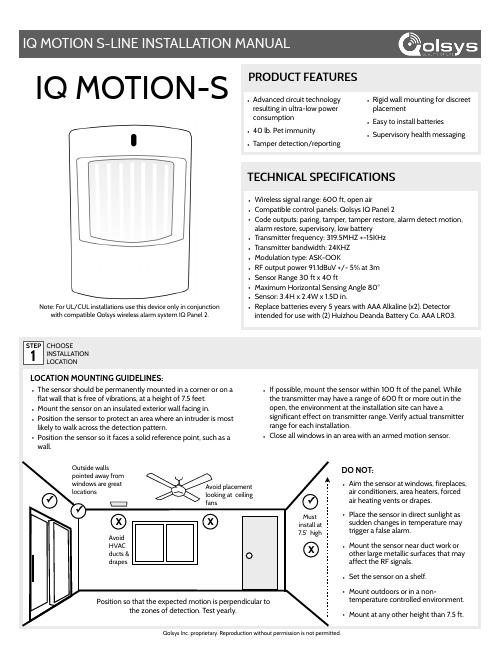
•Advanced circuit technologyresulting in ultra-low powerconsumption•40 lb. Pet immunity•Tamper detection/reporting•Rigid wall mounting for discreetplacement•Easy to install batteries•Supervisory health messagingPRODUCT FEATURESIQ MOTION-S•Wireless signal range: 600 ft, open air•Compatible control panels: Qolsys IQ Panel 2•Code outputs: paring, tamper, tamper restore, alarm detect motion,alarm restore, supervisory, low battery•Transmitter frequency: 319.5MHZ +-15KHz•Transmitter bandwidth: 24KHZ•Modulation type: ASK-OOK•RF output power 91.1dBuV +/- 5% at 3m•Sensor Range 30 ft x 40 ft•Maximum Horizontal Sensing Angle 80°•Sensor: 3.4H x 2.4W x 1.5D in.•Replace batteries every 5 years with AAA Alkaline (x2). Detectorintended for use with (2) Huizhou Deanda Battery Co. AAA LR03.TECHNICAL SPECIFICATIONS•The sensor should be permanently mounted in a corner or on aflat wall that is free of vibrations, at a height of 7.5 feet.•Mount the sensor on an insulated exterior wall facing in.•Position the sensor to protect an area where an intruder is mostlikely to walk across the detection pattern.•Position the sensor so it faces a solid reference point, such as awall.•If possible, mount the sensor within 100 ft of the panel. Whilethe transmitter may have a range of 600 ft or more out in theopen, the environment at the installation site can have asignificant effect on transmitter range. Verify actual transmitterrange for each installation.•Close all windows in an area with an armed motion sensor. STEP1CHOOSEINSTALLATIONLOCATION•Aim the sensor at windows, fireplaces,air conditioners, area heaters, forcedair heating vents or drapes.•Place the sensor in direct sunlight assudden changes in temperature maytrigger a false alarm.•Mount the sensor near duct work orother large metallic surfaces that mayaffect the RF signals.•Set the sensor on a shelf.•Mount outdoors or in a non-temperature controlled environment.•Mount at any other height than 7.5 ft.Qolsys Inc. proprietary. Reproduction without permission is not permitted.LOCATION MOUNTING GUIDELINES:DO NOT:XAvoid placementlooking at ceilingfans✓Outside wallspointed away fromwindows are greatlocationsXAvoidHVACducts &drapesX✓Mustinstall at7.5’ high✓Position so that the expected motion is perpendicular tothe zones of detection. Test yearly.Note: For UL/CUL installations use this device only in conjunctionwith compatible Qolsys wireless alarm system IQ Panel 2.STEP 2REMOVEBATTERY TABSSTEP 4CHOOSEMOUNTING TYPESECUREALLHARDWARELEARNINTO PANELSTEP 5OPENDEVICE CASINGSTEP 3STEP 6Place your panel in “Auto Learn" modeOpen and close the case to “tamper” the deviceCustomize name and settings as desired and and touch “ADD”ADDWalk test mode is activated by opening the motion detector back plate enough to release the tamper switch, then closing it again. During walk test mode the red LED on the front of the detector will light up every time motion is detected. Use this feature to test the coverage pattern of the protected area. The motion detector will remain in walk test mode until there is a period of one minute of inactivity, meaning that no motion is detected for one minute, at which time it will return to normal mode.MODES & BEHAVIORSNORMAL MODE:Normal mode defines the motion detector’s behavior set in which it can detect motion. It is the default state of the sensor, given no motion has been detected. While in normal mode, a motion detector sensor can go into both sleep mode and walk test mode, as is described below. During any given time in normal mode, the motion detector can transmit up to TWO active events. Once the first active event is sent, the motion detector has a 4 second timeout delay before a second active event can be transmitted. After the first active event is sent, a 5 minute timer starts; if a second active event is sent during this 5 minute period, the motion detector will go into sleep mode for the remainder of the 5 minute period. Once this 5 minute period times out, the motion detector returns to its normal behavior where it can transmit two active events. During normal mode, a motion detector will send a supervisory heartbeat to the panel 70 minutes after the last event transmission. If the device has been idle for 70 minutes consecutively, it will send out a heartbeat supervisory transmission.Qolsys Inc. proprietary.Reproduction without permission is not permitted.SLEEP MODE:WALK TEST MODE:Sleep mode defines a limited period when the motion detector does not transmit any active or idle events to the panel in order to conserve battery life. The sleep mode timer last five minutes and starts once the first active event is sent. During this period, if a second active event is transmitted, the motion detector will go into sleep mode until the timer finishes counting down.PET IMMUNITY:The IQ Motion Detector is pet immune up to 40 lbs when mounted at 7.5 feet high and angled downward. Pets must not be allowed to climb on objects such as furniture, shelves, boxes, etc. within the field of coverage (see detection pattern on page 3 of this manual). The detector should not be looking directly at stairs that would allow a pet to walk up them when the panel is armed.Must replace casting screw for UL listed installationFLATCORNERMOUNT AT 7.5 FEET HIGHAAA Alkaline (2 per sensor)Battery life expectancy: 5 years. (Lifetime may varydepending on number of activations, environmentalconditions, etc.)To replace batteries:•Push button on bottom of sensor and remove frombackplate.•Remove old batteries and replace with new ones.•Re-install in reverse order.Operating Temperature: 0˚C~49˚CRelative Humidity: 93% MaxStorage Temperature: -40-80˚CENVIRONMENTALDETECTION PATTERN BATTERY REPLACEMENTTOP VIEW:SIDE VIEW:EquipmentBP21056Document#: IQM-SIM-04-18Revision#: 4/20/18Issue Date: APR 2018Qolsys Part #: QS1231-840**********************Qolsys Inc. proprietary.Reproduction without permission is not permitted.FCC ID: 2AAJXQS1200IC: 11205A-QS1200This device complies with part 15 of the FCC Rules. Operation is subject to the following two conditions: (1) This device may not cause harmful interference, and (2) this device must accept any interference received, including interference that may cause undesired operation. Changes or modifications not expressly approved by the party responsible for compliance could void the user's authority to operate the equipment.This device complies with Industry Canada licence-exempt RSS standard(s). Operation is subject to the following two conditions: (1) this device may not cause interference, and(2) this device must accept any interference, including interference that may cause undesired operation of the device.Cet appareil est conforme avec Industrie Canada exempts de licence standard RSS (s). Son fonctionnement est soumis aux deux conditions suivantes: (1) cet appareil ne doit pas provoquer d'interférences et(2) cet appareil doit accepter toute interférence, y compris celles pouvant causer un mauvais fonctionnement de l'appareil.CONTACT TECH SUPPORTGOT QUESTIONS?SECURECONNECTSUSING319.5 MHz7.5 Feet3.75 Feet15°。
智能家居系统安装与调试手册

智能家居系统安装与调试手册第1章智能家居系统概述 (4)1.1 系统简介 (4)1.2 系统架构 (4)1.3 技术优势 (4)第2章系统安装前期准备 (4)2.1 工具与材料 (5)2.2 环境检查 (5)2.3 设备清点 (5)第3章硬件设备安装 (5)3.1 传感器设备安装 (5)3.2 控制器设备安装 (5)3.3 网络设备安装 (5)第4章软件系统部署 (5)4.1 系统软件安装 (5)4.2 配置网络连接 (5)4.3 系统初始化 (5)第5章传感器调试 (5)5.1 传感器检测 (5)5.2 传感器参数配置 (5)5.3 传感器联动测试 (5)第6章控制器调试 (5)6.1 控制器功能测试 (5)6.2 控制器编程 (5)6.3 控制器联动调试 (5)第7章智能家居APP配置 (5)7.1 APP与安装 (5)7.2 账户注册与登录 (5)7.3 设备添加与绑定 (5)第8章系统功能测试 (5)8.1 照明控制功能测试 (5)8.2 家电控制功能测试 (5)8.3 安全防护功能测试 (5)第9章系统优化与升级 (5)9.1 系统功能优化 (5)9.2 系统功能升级 (6)9.3 系统兼容性测试 (6)第10章常见问题与解决方案 (6)10.1 硬件设备故障处理 (6)10.2 软件系统故障处理 (6)10.3 网络连接故障处理 (6)第11章系统维护与保养 (6)11.2 软件系统维护 (6)11.3 系统数据备份与恢复 (6)第12章用户培训与售后服务 (6)12.1 用户培训 (6)12.2 售后服务流程 (6)12.3 技术支持与咨询 (6)第1章智能家居系统概述 (6)1.1 系统简介 (6)1.2 系统架构 (6)1.3 技术优势 (7)第2章系统安装前期准备 (7)2.1 工具与材料 (7)2.2 环境检查 (7)2.3 设备清点 (8)第3章硬件设备安装 (8)3.1 传感器设备安装 (8)3.1.1 准备工作 (8)3.1.2 安装步骤 (8)3.2 控制器设备安装 (9)3.2.1 准备工作 (9)3.2.2 安装步骤 (9)3.3 网络设备安装 (9)3.3.1 准备工作 (9)3.3.2 安装步骤 (9)第4章软件系统部署 (10)4.1 系统软件安装 (10)4.1.1 准备工作 (10)4.1.2 安装步骤 (10)4.2 配置网络连接 (10)4.2.1 配置以太网连接 (10)4.2.2 配置无线网络连接 (11)4.3 系统初始化 (11)4.3.1 设置系统时间 (11)4.3.2 设置系统区域和语言 (11)4.3.3 配置系统更新 (11)第5章传感器调试 (12)5.1 传感器检测 (12)5.2 传感器参数配置 (12)5.3 传感器联动测试 (12)第6章控制器调试 (13)6.1 控制器功能测试 (13)6.1.1 输出信号测试 (13)6.1.2 电压输出测试 (13)6.1.4 控制装置启动方式检查 (13)6.2 控制器编程 (13)6.2.1 设定联动逻辑 (13)6.2.2 编写单点联动逻辑 (14)6.2.3 总线制与多线控制设置 (14)6.3 控制器联动调试 (14)6.3.1 联动启泵测试 (14)6.3.2 报警阀启动测试 (14)6.3.3 远程手动启泵测试 (14)6.3.4 现场手动启泵测试 (14)第7章智能家居APP配置 (14)7.1 APP与安装 (14)7.2 账户注册与登录 (15)7.3 设备添加与绑定 (15)第8章系统功能测试 (15)8.1 照明控制功能测试 (15)8.1.1 测试目的 (15)8.1.2 测试方法 (15)8.1.3 测试用例 (16)8.2 家电控制功能测试 (16)8.2.1 测试目的 (16)8.2.2 测试方法 (16)8.2.3 测试用例 (16)8.3 安全防护功能测试 (17)8.3.1 测试目的 (17)8.3.2 测试方法 (17)8.3.3 测试用例 (17)第9章系统优化与升级 (18)9.1 系统功能优化 (18)9.1.1 硬件功能优化 (18)9.1.2 软件功能优化 (18)9.2 系统功能升级 (18)9.2.1 操作系统升级 (18)9.2.2 应用软件升级 (18)9.3 系统兼容性测试 (19)第10章常见问题与解决方案 (19)10.1 硬件设备故障处理 (19)10.1.1 检测硬件故障 (19)10.1.2 更换硬件设备 (19)10.1.3 硬件驱动安装 (19)10.2 软件系统故障处理 (19)10.2.1 软件运行错误 (19)10.2.2 系统崩溃 (20)10.3 网络连接故障处理 (20)10.3.1 网络断开 (20)10.3.2 网络延迟 (20)10.3.3 无线网络信号弱 (20)第11章系统维护与保养 (21)11.1 硬件设备维护 (21)11.1.1 日常检查 (21)11.1.2 清洁保养 (21)11.1.3 更换耗材 (21)11.1.4 防止过载 (21)11.2 软件系统维护 (21)11.2.1 定期更新 (21)11.2.2 优化系统 (21)11.2.3 检查病毒 (21)11.2.4 管理软件 (21)11.3 系统数据备份与恢复 (21)11.3.1 备份策略 (21)11.3.2 备份介质 (21)11.3.3 定期备份 (22)11.3.4 恢复演练 (22)11.3.5 远程备份 (22)第12章用户培训与售后服务 (22)12.1 用户培训 (22)12.1.1 培训目标 (22)12.1.2 培训内容 (22)12.1.3 培训方式 (22)12.2 售后服务流程 (22)12.2.1 报修流程 (23)12.2.2 配件更换流程 (23)12.3 技术支持与咨询 (23)12.3.1 技术支持 (23)12.3.2 咨询服务 (23)第1章智能家居系统概述1.1 系统简介1.2 系统架构1.3 技术优势第2章系统安装前期准备2.1 工具与材料2.2 环境检查2.3 设备清点第3章硬件设备安装3.1 传感器设备安装3.2 控制器设备安装3.3 网络设备安装第4章软件系统部署4.1 系统软件安装4.2 配置网络连接4.3 系统初始化第5章传感器调试5.1 传感器检测5.2 传感器参数配置5.3 传感器联动测试第6章控制器调试6.1 控制器功能测试6.2 控制器编程6.3 控制器联动调试第7章智能家居APP配置7.1 APP与安装7.2 账户注册与登录7.3 设备添加与绑定第8章系统功能测试8.1 照明控制功能测试8.2 家电控制功能测试8.3 安全防护功能测试第9章系统优化与升级9.1 系统功能优化9.2 系统功能升级9.3 系统兼容性测试第10章常见问题与解决方案10.1 硬件设备故障处理10.2 软件系统故障处理10.3 网络连接故障处理第11章系统维护与保养11.1 硬件设备维护11.2 软件系统维护11.3 系统数据备份与恢复第12章用户培训与售后服务12.1 用户培训12.2 售后服务流程12.3 技术支持与咨询第1章智能家居系统概述1.1 系统简介智能家居系统,又称智能住宅系统,是一种集成了计算机技术、网络通信技术、自动控制技术、音视频技术等多种先进技术的综合性家居管理系统。
霍尼韦尔 Honeywell安防系统安装和设置指南

4 系统操作 ................................................................................................................................. 42
4.1 安全密码 .......................................................................................................................... 42 4.2 紧急键.............................................................................................................................. 42 4.3 键盘功能 .......................................................................................................................... 43 4.4 报警声音通知(双向语音功能)...................................................................................... 44 4.5 “Follow Me”提示功能..................................................................................................... 45 4.6 “Follow Me”系统语音播放功能 ...................................................................................... 46 4.7 退出错误警报显示 ........................................................................................................... 46 4.8 故障情形 .......................................................................................................................... 46 4.9 测试模式 .......................................................................................................................... 47
Honeywell对讲、智能家居调试安装指导-智能家居篇V1058
Public IP Address
APT Server
Private IP Address
W/G Switch
has
2 IP addresses
☞APT Server has 2 IP address; - One is Public IP address that is used for remote access and control
Honeywell Network
智能家居系统安装调试-网络系统
智能家居网络系统架构
Honeywell 智能家居网络系统: 1. 主干交换机、二级交换机; 2. 防火墙; 3. 公网出口,否则不支持远程控制; 4. GATEWAY 5. APT Server
注意: 防火墙需要对外网打开以下端口,供APT服务器和远程监视、控制使用: 80 (HTTP Port), 8020 (ActiveX), 21 and 20 (FTP Port), 5432 (DB Port), 22(SSH Port), (注意,如果需要做权限管理,需要专人配合管理22端口) 8008 (Port for Monitoring). 8080 and 8000(Port for debugging Web Server).
I P: 10.0.4.200/24 GW:
10.0.4.254/24
I P: 10.0.1.11/24 GW:
10.0.1.254/24
12
HONEYWELL -
智能家居系统安装调试-网络系统
* About IP Address
1) Public and Private IP Addresses Only public IP addresses can be accessed from the Internet. Public addresses are unique world wide. Private addresses are for use in private networks although these private addresses can be translated to public addresses.
霍尼韦尔智能家居系统解决方案

霍尼韦尔智能家居系统地区总经销商鸣迅智能科技有限公司目录一、公司背景┅┅┅┅┅┅┅┅┅┅┅┅┅┅┅┅2二、智能住宅┅┅┅┅┅┅┅┅┅┅┅┅┅┅┅┅3三、系统介绍┅┅┅┅┅┅┅┅┅┅┅┅┅┅┅┅5四、系统功能┅┅┅┅┅┅┅┅┅┅┅┅┅┅┅┅61.系统整体介绍‐‐‐‐‐‐‐‐‐‐‐‐‐‐‐‐62.防盗报警‐‐‐‐‐‐‐‐‐‐‐‐‐‐‐‐‐‐63.灯光窗帘控制‐‐‐‐‐‐‐‐‐‐‐‐‐‐‐‐94.地板采暖控制‐‐‐‐‐‐‐‐‐‐‐‐‐‐‐‐105.空调控制‐‐‐‐‐‐‐‐‐‐‐‐‐‐‐‐‐‐116.远程视频监控‐‐‐‐‐‐‐‐‐‐‐‐‐‐‐‐12五、主要产品说明┅┅┅┅┅┅┅┅┅┅┅┅┅┅131.控制面板‐‐‐‐‐‐‐‐‐‐‐‐‐‐‐‐‐‐142.智能家居主机‐‐‐‐‐‐‐‐‐‐‐‐‐‐‐‐153.智能控制模块‐‐‐‐‐‐‐‐‐‐‐‐‐‐‐‐16六、产品优势┅┅┅┅┅┅┅┅┅┅┅┅┅┅┅191.品牌的优势‐‐‐‐‐‐‐‐‐‐‐‐‐‐‐‐‐192.高度集成化的系统‐‐‐‐‐‐‐‐‐‐‐‐‐‐193.开放系统,国际标准的通讯协议‐‐‐‐‐‐‐‐204.稳定的产品质量‐‐‐‐‐‐‐‐‐‐‐‐‐‐‐20七、具体案┅┅┅┅┅┅┅┅┅┅┅┅┅┅┅20八、案例介绍┅┅┅┅┅┅┅┅┅┅┅┅┅┅┅20九、售后服务承诺┅┅┅┅┅┅┅┅┅┅┅┅┅241.售后服务主导思想坚持质量第一,用户至上的精神维护本公司的声誉,确保工程项目及产品售后服务发挥其应有的效能‐242.售后服务围‐‐‐‐‐‐‐‐‐‐‐‐‐‐‐‐243.实施办法‐‐‐‐‐‐‐‐‐‐‐‐‐‐‐‐‐‐24一、公司背景霍尼韦尔(Honeywell)公司是一家年销售额达300 亿美元,在多元化科技和制造业领域占据世界领导地位的跨国公司。
在全球,其业务涉及航空产品及服务、住宅及楼宇控制和工业控制技术、自动化产品、特种化学、纤维、塑料以及电子和先进材料等领域。
霍尼韦尔公司在全球95 个拥有10.8 万员工,总部设在美国新泽西州莫里斯镇。
Honeywell智能家居系统介绍
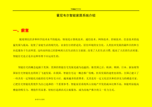
霍尼韦尔智能家居系统介绍一、前言随着国民经济和科学技术水平的提高,特别是计算机技术、通信技术、网络技术、控制技术、信息技术的迅猛发展与提高,促使了家庭生活的现代化,衣食住行的舒适化,居住环境的安全化。
人类技术发展的最终目的和方向是服务于生活所需,这些高科技已经影响到人们生活的方方面面,改变了人们生活习惯,提高了人们的生活质量,智能住宅也正是在这种形势下应运而生的。
智能住宅的概念起源于美国,美国的智能住宅发展是最为迅猛的。
继美国之后,欧洲、韩国、日本、新加坡等国家住宅智能化也得到了飞速发展。
在我国,智能住宅这一概念推广较晚,但其发展的速度也很快,全国已建立了一些具有一定智能化功能的住宅和住宅小区。
越来越多的消费者,尤其是有一定文化层次和经济实力的楼盘买家,已把住宅智能化程度作为自己选择的一个重要参考。
智能家居系统所占房地产开发的成本比例不高,却能明显提高楼盘的吸引力,增值作用显著,轻松打造酒店式公寓服务,成为房地产推介的又一有力方式。
智能住宅是将家庭中各种与信息相关的通讯设备、家用电器和家庭保安装置,通过家庭总线技术连接到一个家庭智能化系统上进行集中的或异地的监视、控制和家庭事务性管理,并保持这些家庭设施与住宅环境的和谐与协调。
如何构建一个智能网络化家庭?下面描述了一个网络化家庭的生活景象,也许这正是你我的梦想。
星期五上午6:50室外的灯自动关闭。
——上午7:15;主人出门上班,将安全程序设定为“离开”方式。
以家庭网关为核心的控制系统自动将不必要的灯以及危险设备关闭;恒温器自动进行调整以节省能源,窗帘自动关闭,安防系统进入监视状态;——下午:主人给家中控制系统打一个电话,控制系统通知主人,孩子在下午四点回到了家里,他们输入了正确的开门号码并打开了洗碗机,通过Internet,主人输入正确的用户名和密码,通过公寓服务器的身份验证后,启动安装在家中的网络摄像机,看到孩子们正在安全地做游戏。
——晚上:主人回到家中,汽车通道传感器自动进行100%的照明,车库门打开,车库中照明灯开启,车辆停泊好后,主人进入客厅,五分钟之后灯关闭。
Honeywell 对讲、智能家居调试安装指导-总线对讲篇V1.0
3
HONEYWELL -
总线级对讲系统安装调试
主机名称 描述 型号 图示
可视主机 (室内终端)
安装于各个用户室内,与其他室内主机、公共单元门口机进行通讯。 并且集成了安防功能。根据主机型号的不同,防区的数目也有不同。 主机的通讯状态和安防状态都可以通过HBUS系统上传到总线管理软件 HS-7500K Server MUI。
1号辅控器
2号辅控器
„ 去第五组
注意
7号辅控器
8号辅控器
7号辅控器
8号辅控器
6
HONEYWELL -
SCTR和HVP之间的接线图
GRD1 GRD2 总线1 SCTR配线板 红线 大厅电 话 1 绿线 绿线 3 3
D+/-
* 注:接线说明 1 - UTP:数据为1P 2 语音为2P,1P NC - UTP CAT5 4P:12V/GND为1P 音频/视频为1P 视频选择为1P - UTP:数据为1P,语音为1P - 同轴电缆:SYV75-5/75-7
辅控器 UTP,CAT5 Power AC220V RVV2*0.5开锁信号
视频放大器安装箱
从IF471切出的视频,由视频分配放大器 向室内主机处传输,形式灵活。可以用 若干个视频分配器进行树型的分配,也 可以以IF172来串接。 另外视频分配放大器也可以根据项目实 际情况找专业厂家订做。
16
HONEYWELL -
总控器端为422端口,监控电脑端为232串口,需要加422-232转换模块。
• • 住户终端信息(管理数据)可以通过HS-7500K Server MUI配置后下载到MCTR、S CTR内。 每个附控逻辑上限制不超过4个单元,每个实际物理单元不能超过四个附控支持。
- 1、下载文档前请自行甄别文档内容的完整性,平台不提供额外的编辑、内容补充、找答案等附加服务。
- 2、"仅部分预览"的文档,不可在线预览部分如存在完整性等问题,可反馈申请退款(可完整预览的文档不适用该条件!)。
- 3、如文档侵犯您的权益,请联系客服反馈,我们会尽快为您处理(人工客服工作时间:9:00-18:30)。
WAP Application
Home Server
• 通过移动设备WAP服务进行控制
WEB Application
• 通过网络浏览器进行远程控制
智能家居系统安装调试-网络系统
• APT Server软件介绍
智能家居系统安装调试-网络系统
• 配置网络服务器、内网所需基本设备
智能家居系统安装调试-室内部分HS-7000N接线
步骤 1. 内置 TB-7000于底盒内.
•前提是底盒已经预埋在墙体内 ,室内终端设备及探测器线缆已经接入底盒。 • 将TB7000放入底盒内,用两个螺丝在相应位置做固定。
置入后螺丝固定。
智能家居系统安装调试-室内部分HS-7000N接线
步骤2. 连接电源、感应探测器及设备
智能家居系统安装调试
智能家居系统的组成
Honeywell 智能家居系统可以对室内的灯光、窗帘、新风、空调以及 防区探头等进行监控。
Gateway网关是进行户内、户外的接口设备,室内通过触摸屏对室内设 备进行控制,系统级别通过Honeywell HBUS,局域网进行双网冗 余的联网。
• 智能社区内部局域网络 • 总线系统级设备 • 智能家居网关、触摸屏终端主机(HS7000N/HS7000VE/HS5000) • 网络型管理机HI-750W、网络型公共单元门口机HLP1000-W。 • 总线管理软件 HS-7500K Server MUI • 中央管理服务器APT Server
Router
Firewall
Switch
Router Firewall
W/G Switch
B/B Switch
Web (WAP) Server DB Server
Developer’s Portal Site
Monitoring System
Honeywell Network Server
Honeywell server : Main/Control Server + DB server for the complex
注意: 防火墙需要对外网打开以下端口,供APT服务器和远程监视、控制使用: 80 (HTTP Port), 8020 (ActiveX), 21 and 20 (FTP Port), 5432 (DB Port), 22(SSH Port), (注意,如果需要做权限管理,需要专人配合管理22端口) 8008 (Port for Monitoring). 8080 and 8000(Port for debugging Web Server).
Washing Dish
Air
Machine Washer Conditioner
Power Line Control
RS-485
Thermostats
RS-485
Light
Gas Valve
Security Sensors
HS-7000
Analog A/V
Door camera
TCP/IP
Internet
UT P C AT 5
排线描述
棕白 绿白
绿 蓝
+12V 接红线 GND 接黑线 AUD 接黄线 VID 接蓝线
MTU值设置最好大于1800 防火墙设置为透明模式 内网容量 100左右 两层交换机
Honeywell Network
智能家居系统安装调试-网络系统
APT Server 特性和功能
Main Server
• 监视、控制、提供远程服务。 • 用户授权和认证
Control server
• 与每一个室内网关联接 • 支持网关、服务器之间的数据
Hale Waihona Puke I P: 10.0.4.200/24 GW:
10.0.4.254/24
I P: 10.0.1.11/24 GW:
10.0.1.254/24
智能家居系统安装调试-网络系统
* About IP Address
1) Public and Private IP Addresses Only public IP addresses can be accessed from the Internet. Public addresses are unique world wide. Private addresses are for use in private networks although these private addresses can be translated to public addresses.
• .开关确认OFF位置。
连接AC220V电源至该端口
确认此时电源开关在 OFF位置。
智能家居系统安装调试-室内部分HS-7000N接线
室内网关设备接口
• 室内网关设备连接至接线板的8个RJ-45接口上
DCAM2 GRD
SUBP2 SUBP1
•接线头 •线缆
: RJ-45 : UTP CAT5e
DCAM1 SUBP2 SUBP2 SUBP1
Honeywell对讲智能家居调 试安装指导智能家居篇
V1058
智能家居系统安装调试
一. Honeywell智能家居系统的组成 二. 系统级搭建指导-网络、总线系统。 三. 室内产品介绍、具体施工搭建要点、施工规
范、图例 四. 调试指导 五. 常见故障及建议解决办法
智能家居系统安装调试
一. Honeywell智能家居系统的组成
[Legends]
Gigabit Ethernet 100Mbps Ethernet
Lobby Phone
Guard Phone
W/G Switch
House
Switch
Desktop Home Gateway
Honeywell Network
智能家居系统安装调试-网络系统
智能家居网络系统架构
Honeywell 智能家居网络系统: 1. 主干交换机、二级交换机; 2. 防火墙; 3. 公网出口,否则不支持远程控制; 4. GATEWAY 5. APT Server
(2) Private IP Address a. Static b. dynamic
智能家居系统安装调试-网络系统
Internet
对网络的设计和规划
Router
VLan1: 10.0.1.100/24 VLan2: 10.0.2.254/24 VLan3: 10.0.3.254/24 VLan4: 10.0.4.254/24
Often, the addresses that are assigned directly to your computer and server are not public addresses. If you obtain an IP address, check to make sure it is not a private address. Private addresses fall within the following ranges:
HOME CONTROL (WEB control)
Room 1
Room 2
Bathroom
Kitchen A/V
Honeywell Network Server
智能家居系统安装调试-网络系统
对WEB/WAP控制的要点确认
1. 是否需要 WEB/WAP 控制服务;
2. 能否为服务器提供外网静态IP?至少需要两个静态IP,分别供防火墙 和APT Server使用;
Firewall #1
B/B Switch
W/G Switch
[Legends]
COLOR LINE Gigabit Ethernet 100Mbps Ethernet
Server (VLan1)
APT Server
AMS
IP Range: 10.0.1.111 ~ 120/24, GW: 10.0.1.110/24
W/G Switch
W/G Switch
W/G Switch
W/G Switch
W/G Switch
W/G Switch
Budg- 101 ( VLAN2 )
IP Range: 10.0.2.1 ~ 240/24 Gateway: 10.0.2.254/24
Budg- 102 ( VLAN3 )
IP Range: 10.0.3.1 ~ 240/24 Gateway: 10.0.3.254/24
3. 需要域名吗?我们推荐使用;
1. 其他要点确认: 2. 3. 网络设备的维护和使用权责确定;实际项目中一般将网络搭建工程外包给
专业网络公司,集成商或者代理商提需求。
4. 社区局域网内除了要按照配置参数表部署APT Server 服务器,还需要配置 AMS软件用PC机。
5. 智能社区内网不做限制,可以划分VLAN;强烈推荐智能社区内网与小区上 网分别建立独立隔离网络。
Budg- 103 ( VLAN4 )
IP Range: 10.0.4.1 ~ 240/24 Gateway: 10.0.4.254/24
House
Switch
Desktop
Home Gateway I P: 10.0.4.11/24
GW: 10.0.4.254/24
智能家居系统安装调试-网络系统 HS-7000N 网络系统架构示意
Ex)
Public IP Address
Private IP Address
APT
Client
Server
W/G Switch
has
2 IP addresses
☞APT Server has 2 IP address; - One is Public IP address that is used for remote access and control