547-211日本三丰数显深度尺说明书
电子数显千分尺说明书

液晶显示屏:
按键功能及操作: 按键操作有两种方法:(1)按键(时间< 2 秒); (2)持续按键(时间>= 2 秒)
●ON/OFF•••SET:开关键、延时设置键 按键动作< 2 秒:开、关数显尺电源 按键动作>= 2 秒:设置数显尺的绝对测量初始值;显示“Set”。 公制模式下,不同测量范围的数显尺其初始值分别为 0, 25, 50 ••• 275mm; 英制模式下,不同测量范围的数显尺其初始值分别为 0, 1″, 2″••• 11″。 重新安装电池后,自动进行初始值设置。 微分头的默认初始值为 0。
电源:
●数显尺使用一粒 SR44 电池。当液晶屏显示的数字模糊不清或 “
”显示时,请更换电池。
●5 分钟内不使用数显尺,数显尺将会自动断电,当转动丝杆或按动“ON/OFF•••SET”键时,数显尺
恢复自动断电前显示的数值。不使用时,请按下“ON/OFF•••SET”键,关闭电源,以节省电池。
●用一枚硬币插入电池盖槽中,顺时针方向旋转,松开电池盖。取出废电池。
原因
计算数据溢出。
1. 周边有干扰,或者传感器间有异物进 入使得传感器出错。
2. 传感器故障。 1. 测量面是否有污物。 2. 设置值是否设置准确。 1. 电池安装是否正确。 2. 电池是否没电。 1. 电池电压是否小于 1.45V。 2. 电池电压是否小于 1.45V。 3. 电池安装是否正确。
电池电压是否小于 1.45V。
2
(线缆插头具有防水性能,不可拆下线缆插头的橡胶帽)
●数据输出口参数:
波特率
1200kB/S
停止位
2
启始位
1
奇偶位
无
●数据输出格式:
日本三丰精密测量仪器的小常识

消除误差的注意事项
可能产生 的误差
即使加以注 意也无法消 除的误差
■虎克定律
往具有某一长度与断面的物体上施加负荷时,在弹性限度内 引起伸缩位移量的定律。
螺距误差 (被测量物)
半角误差 (被测量物)
1. 进行螺距误差的补正δp =δE 2. 测量几个点,取平均值。 3. 减少单一螺距误差。(工作)
1. 使用最佳针径。 2. 无需补正
螺距误差为 0.02mm 时 ±18µm ±3µm
±0.3µm
±0.3µm
■赫兹公式
赫兹公式给出了在弹性范围内两个表面 (平坦表面、圆柱面或 球型) 在某种作用力相互挤压时表面的变形度,并且作为计算
1. 使用最佳针径。 三针径的误差 2. 在侧面使用接近平均直径的
测头。
±8µm
测力的影响
1 使用符合螺距的规定的测力。 2. 按照测量端面的面积规定。 -3µm 3. 应为稳定的测力。
三个槽 M=(3M1 - 2D) (1)
五个槽 M=(2.2360M1 - 1.23606D)
米制螺纹 (60˚) 时 E=M - 3d + 0.866025P (2)
惠式螺纹 (55˚) 时 E=M - 3.16567d + 0.96049P
螺纹的形式 米制螺纹 (60˚) 惠式螺纹 (55˚)
指针的最佳针径 0.557p 0.564p
(单位:mm)
安装方法
①螺母固定方式
②铣口固定方式
③螺丝固定方式
A面
注意点 测杆直径
安装孔 配合公差
注意事项
Ø9.5
Ø10
G7 +0.005~+0.020
Ø12
Ø18
G7 +0.006~+0.024
高度尺的使用方法及注意事项

对高度尺进行相对应的加减
数显高度尺的使用方法:
用途:用于测量零件的高度和精密划线
先把测量爪在要测量的零 件尺寸一端归零
正确测量方法
ห้องสมุดไป่ตู้再把测量爪移至要测量的零件尺 寸的另一端,显示屏上所显示的
数值即为零件的高度
错误测量方法
本内容仅供参考,如需使用,请根据自己实际情况更改后使用!
放映结束 感谢各位批评指导!
数显高度尺的使用方法
数显高度尺的结构型式 此数显高度尺的测量范围0-300mm 其最小表示量0.01mm
压板 尺身
保护膜
微动装置
ON/OFF/ZERO键
HOLD锁定键 测量爪/ 划线爪
锁紧框 尺框 尺座
显示屏 紧固螺钉
电池盖
一、校正
标准块
先把测量爪在干净的 水平台上归零
然后用标准块进行校正,如测量 值与标准值有偏差,测量时,则
精密测量工具指南 - 计尺、高度尺、深度尺等说明书

ABSOLUTEDigimatic CaliperABSOLUTECoolant-Proof CaliperSuper CaliperDigimatic HeightGage500-784Direction of the lengthDirection of the lengthRa: 0.126µmRa: 0.07µm• With thumb roller.• Supplied in fitted plastic case. 500-474Technical DataAccuracy: Refer to the list of specifications Resolution: .0005"/0.01mm or 0.01mm Repeatability: .0005” / 0.01mm Display: LCD• Supplied in fitted plastic case.500-763-20500-752-20Measurement data output function is available 05CZA624Technical DataAccuracy: Refer to the list of specifications Resolution: .0005”/0.01mm or 0.01mm Repeatability: .0005”/ Display: LCD Direction of the lengthDirection of the lengthwooden case.959143959149500-197-30500-151-30The new Mitutoyo ABS Digimatic Caliper line with500-502-10500-501-10500-500-10505-732505-745505-742-56.100” per revolution.200” per revolution1mm per revolution2mm per revolution505-7461. Outside measurement2. Inside measurement3. Step measurement4. Depth measurement530-101530-109Carbide-tippedCarbide-tipped jaw typeRound depth bar typeOD measurementID measurementStep measurementDepth measurement531-101Thumb clampStep measurementDepth measurementOD measurementID measurement532-101 OD measurementID measurementStep measurementDepth measurement160-101160-116160-131 550-311-10534-114552-314-10552-155-10FunctionOrigin-set, Zero-setting, Presetting, Offsetting, Data hold,Centerline Attachments Pointed ID MeasuringAttachment Clamps552-151-10 Ceramic jaws552-192-10 with optional interchangeable jaws573-117-10(Center-to-center type)573-119-10(Edge-to-center type) SPECIFICATIONS536-101 573-701-20573-705-20536-105 SPECIFICATIONSto obtain.573-721-20536-121573-734-20 536-134573-751-20536-151536-152Point jaw typeSPECIFICATIONSMetric Range Order No.Accuracy Resolution Mass(g)573-761-20536-161Digital model• Supplied in fitted plastic case.to allow quick and efficient go/no-goSPECIFICATIONSMetric Range Order No.Accuracy Resolution SPECIFICATIONSMetric Measurement procedures• Supplied in fitted plastic case.573-191-30573-282-30Technical DataAccuracy: Refer to the list of specifications Resolution*: .0005”/0.01mm / 0.01mm Graduation**: 0.05mm Display*: LCDLength standard*: ABSOLUTE electrostatic capacitance type linear encoderMax. response speed*: Unlimited 573-742-20536-142536-145536-146573-746-20573-745-20wooden case.Point-jaw type700-113-10 700-123-10050001Application for 4”, 6” and 8” Vernier,Dial and Digimatic Calipers, requiringdimensions over .375”.Depth baseattachmentD-34■ NomenclatureSliderBeam Reference surfaceMain scale Depth barDepth measuring facesThumb-rollerZERO Set/ABSOLUTE buttonOutput connectorLocking screwOutside measuring facesOutside jawsInside jaws Inside measuring faces Step measuring faces本尺目盛目盛板本尺目盛バーニヤ目盛■ How to Read the Scale●Dial Calipers●Vernier CalipersGraduation 0.01mmMain scale16 mm Vernier 0.15 mm Reading16.15 mmGraduation 0.05mm(1)(2)Main scale 16 mm Dial face 0.13 mm Reading16.13 mm(1)(2)Graduation 0.05mm(1)(2)Main scale reading 16 mmDial face reading 0.13 mmDial Caliper reading 16.13 mm (1)(2)0Main scale Dial faceMain scale Vernier scale501080307090406020010203040(1)(1)(1)(2)(2)(2)(2)Main scaleDial face501080307090406020②①001234567891010203040■ Special Purpose Caliper ApplicationsPoint jaw typeOffset jaw typeDepth typeBlade jaw typeFor uneven surface measurementFor stepped feature measurement For depth measurementFor diameter of narrow groove measurementVernier CaliperAbsolute Digimatic Caliper ■ Measurement applications1. Outside measurement2. Inside measurement4. Depth measurement3. Step measurementNote) Above left, 0.15 mm (2) is read at the position where a main scale graduation line corresponds with a verniergraduation line.CalipersQuick Guide to Precision Measuring InstrumentsStep measuring facesGib, sliderLocking screwScrew, gib pressingBeamStopper, sliderDepth measuring facesMain scale Reference surfaceThumbwheelVernier scale SliderInside measuring faces Inside jaws Outside jawsOutside measuring facesScrew, gib setting Depth barD-35■ About Long CalipersSteel rules are commonly used to roughly measure large workpieces, but if more accuracy is needed, then a long caliper is suitable for the job. A long caliper is convenient for its user friendliness but does require some care during use. In the first place it is important to realize there is no relationship between resolution and accuracy. For details, refer to the values in our catalog. Resolution is constant whereas the accuracy obtainable varies dramatically according to how the caliper is used.The measuring method with this instrument is a concern since distortion of the main beam causes a large amount of the measurement error, so accuracy will vary greatly depending on the method used for supporting the caliper at the time. Also, be careful not to use too much measuring force when using the outside measuring faces as they are furthest away from the main beam so potential errors will be at a maximum here. This precaution is also necessary when using the tips of the outside measuring faces of a long-jaw caliper.■ Vernier scaleThis is a short auxiliary scale that enables accurate interpolation between the divisions of a longer scale without using mechanical magnification. The principle of operation is that each vernier scale division is slightly smallerthan a main scale division, so that successive vernier graduations successivelycoincide with main scale graduations as one is moved relative to the other. Specifically, n divisions on a vernier scale are the same length as n-1 divisions on the main scale it works with, and n defines the division (or interpolation) ratio. Although n may be any number, in practice it is typically 10, 20, 25, etc., so that the division is a useful decimal fraction. The example below is for n = 10. The main scale is graduated in mm, and so the vernier scale is 9mm (10 divisions) long, the same as 9mm (9 divisions) on the main scale. This produces a difference in length of 0.1mm (1) as shown in figure A (the 1st vernier graduation is aligned with the first main scale graduation). If the vernier scale is slid 0.1mm to the right as shown in figure B, the 2nd graduation line on the vernier scale moves into alignment with the 2nd line on the main scale (2), and so enables easy reading of the 0.1mm displacement.Some early calipers divided 19 divisions on the main scale by 20 vernier divisions to provide 0.05mm resolution. However, the closely spaced lines proved difficult to read and so, since the 1970s, a long vernier scale that uses 39 main scale divisions to spread the lines is generally used instead, as shown below.1234567891024681010203040304050607039mm19mm 0.05mmScale reading 1.45mm Scale reading 30.35mm Calipers were made that gave an even finer resolution of 0.02mm. These required a 49-division vernier scale dividing 50 main scale divisions. However,they were difficult to read and are now hard to find since digital calipers with an easily read display and resolution of 0.01mm appeared.■ Inside Measurement with a CM-type CaliperBecause the inside measuring faces of a CM-type caliper are at the tips of the jaws, the measuring face parallelism is heavily affected by measuring force, and this becomes a large factor in the measurement accuracy attainable. In contrast to an M-type caliper, a CM-type caliper cannot measure a very small hole diameter because it is limited to the size of the stepped jaws,although normally this is not an inconvenience as it would be unusual to have to measure a very small hole with this type of caliper. Of course, the radius of curvature on the inside measuring faces is always small enough to allow correct hole diameter measurements right down to the lowest limit (jaw closure).Mitutoyo CM-type calipers are provided with an extra scale on the slider for inside measurements so they can be read directly without the need for calculation, just as for an outside measurement. This useful feature eliminates the possibility of error that occurs when having to add the inside-jaw-thickness correction on a single-scale caliper.■ Small hole measurement with an M-type caliperStructural error (d) occurs when you measure the internal diameter of a small hole.øD : True internal diameter ød : Measured diametert 1, t 2: Thickness of the inside jaw C: Distance between the inside jaws d: Measurement error (øD – ød)True internal diameter (øD: 5mm) Unit: mm t 1+t 2+C 0.30.50.7d 0.0090.0260.047For inside onlyFor outside only● 19mm Vernier scale● 39mm vernier scale (long vernier scale)ød t 2t 1C øDød øDveC-type Standard outside measurementInside measurement of a stepped hole Measurement of a stepped part CN-typeStandard outside measurement Measurement of a stepped hole Measurement of a stepped part1234567891024681010203040304050607039190.05mm9mm (9 graduation lines)(1) 0.1mm 0.1mmDivided into10 equal divisionsAB(2) Aligned518-351A-215.7” color LCD55inch type: ø3/8”mm type: ø8øA 957262(45)54ø85.3)ø4ø6ø19ø14ø1485ø8øø2 ruby ball probeTechnical DataMeasuring range*:Slider stroke:Resolution:Accuracy at 20°C:Guiding method:Drive method:Length standard:Measuring force:Display: LCDPower supply:Battery operation time: Refer to the list of specifications* Maximum values are obtained with the probe at thehighest position. Any change of the probe orientationrequires the coordinate system be re-zeroed. With the probein the highest position, minimum measurable height is4.53”/115mm.64PKA129AShown with optional touch-signal probeSPECIFICATIONSInch/MetricRange0-12”/0-300mm0-18”/0-450mm0-24”/0-600mm0-40”/0-1000mmMetricRange0-300mm0-600mm0-1000mm192-630-10192-150Comfortable grip baseEasy and secure clampingEasy and error-free readingSPECIFICATIONSMetricRange0 - 200mm0 - 1000mmInch/MetricRange0 - 8" /0 - 200mm0 - 40" /0 - 1000mm570-244570-312570-304Large, smooth slider-feed wheelLarge clamp leverComfortable grip base• Zero reference point can be adjusted.• Satin chrome-finished scales for glare-free• Optional magnifier for easier reading514-102514-103506-207506-208 SPECIFICATIONSCenter Master509-302Dial type:250mm192-140Digital type:12"192-141Digital type:18"192-142Digital type:24"192-143Digital type:40"192-616Digimatic type:12"/300mm192-617Digimatic type:18"/450mm 07GZA032 2.4" x 1.2" x .25" x .5"192-618Digimatic type:24"/600mm192-619Digimatic type:40"/1000mm570-233Digimatic type:12"/300mm570-234Digimatic type:18"/450mm570-235Digimatic type:24"/600mm574-212-1A Digimatic type:12"/300mm 901385817282Scribing stylusReference surface0182745Scribing stylus Reference surfaceMeasuring upwards from a reference surface ●Vernier Height gage■ How to read(1) Main scale 79mm (2) Vernier 0.36 mm Reading79.36 mmGraduation 0.02mmCounter 124 mm Dial 0.11 mm Reading124.11 mmMain scale Vernier scale 0(1)(2)817282Scribing stylusReference surface182745Scribing stylus Reference surface Measuring upwards from a reference surface ●Mechanical Digit Height gageGraduation 0.02mm Measuring downwards from a reference surface Counter122 mmDial 0.11 mm Reading122.11 mmCounter124 mmDial 0.11 mm Reading 124.11 mm Main scaleVernier scale0■ General notes on use of Height Gages1. Potential causes of errorLike the caliper, the error factors involved include parallax effects, error caused by excessive measuring force due to the fact that a height gage does not conform to Abbe's Principle, and differential thermal expansion due to a temperature difference between the height gage and workpiece.There are also other error factors caused by the structure of the height gage. In particular, the error factors related to a warped reference edge and scriber installation described below should be studied before use.2. Reference edge (column) warping and scriber installationLike the caliper, and as shown in the following figure, measurement errors result when using the height gage if the reference column, which guides the slider,becomes warped. This error can be represented by the same calculation formula for errors caused by nonconformance to Abbe's Principle.Installing the scriber (or a lever-type dial indicator) requires careful consideration because it affects the size of any error due to a warped reference column by increasing dimension h in the above formula. In other words, if an optional long scriber or lever-type dial indicator is used, the measurement error becomes larger.■ Notes on using the height gage1. Keep the column, which guides the slider, clean. If dust or dirt accumulates on it, sliding becomes difficult, leading to errors in setting and measuring.2. When scribing, securely lock the slider in position using the clampingarrangements provided. It is advisable to confirm the setting after clamping because the act of clamping on some height gages can alter the setting slightly. If this is so, allowance must be made when setting to allow for this effect.3. Parallelism between the scriber measuring face and the base reference surface should be 0.01 mm or better.Remove any dust or burrs on the mounting surface when installing the scriber or lever-type dial indicator before measurement. Keep the scriber and other parts securely fixed in place during measurement.4. If the main scale of the height gage can be moved, move it as required to set the zero point, and securely tighten the fixing nuts.5. Errors due to parallax error are not negligible. When reading a value, always look straight at the graduations.6. Handling after use: Completely wipe away any water and oil. Lightly apply a thin coating of anti-corrosion oil and let dry before storage.7. Notes on storage:Avoid direct sunlight, high temperatures, low temperatures, and high humidity during storage.If a digital height gage will not be used for more than three months, remove the battery before storage.If a protective cover is provided, use the cover during storage to prevent dust from adhering to the column.Example: Effect of measuring point positionWhen h is 150 mm, the error is 1.5 times larger than when h is 100 mm.4. Error due to inclination of the main scale (column)According to JIS standards, the perpendicularity of the column reference edge to thebase reference surface should be better than:This is not a very onerous specification. For example, the perpendicularity limitallowable is 0.61 mm when L is 600 mm. This is because this error factor has a small influence and does not change the inclination of the slider, unlike a warped column.5. Relationship between accuracy and temperatureHeight gages are made of several materials. Note that some combinations of workpiece material, room temperature, and workpiece temperature may affect measuring accuracy if this effect is not allowed for by performing a correction calculation.6. The tip of a height gage scriber is very sharp and must be handled carefully if personal injury is to be avoided.7. Do not damage a digital height gage scale by engraving an identification number or other information on it with an electric marker pen.8. Carefully handle a height gage so as not to drop it or bump it against anything.3. Lifting of the base from the reference surfaceWhen setting the scriber height from a gauge block stack, or from a workpiece feature, the base may lift from the surface plate if excessive downwards force is used on the slider, and this results in measurement error. For accurate setting, move the slider slowly downwards while moving the scriber tip to and fro over the gauge block surface (or feature). The correct setting is when the scriber is just felt to lightly touch as it moves over the edge of the surface. It is also necessary to make sure that the surface plate and height gage base reference surface are free of dust or burrs before use.f = h = h a0.01+ 1000L( )mm L indicates the measuring length (unit: mm)lfhahhfhahhHeight GagesQuick Guide to Precision Measuring Instruments• The CERA Caliper Checker also standsperpendicular to a surface for height515-555 Used for caliperUsed for height gage329-350-30 129-109。
卡尺操作手册

平和精工汽车配件有限公司一:目的为了指导使用人员正确使用及维护此测量仪器,避免因操作失误而影响测量数据的准确性,特制定本操作手册二:适用范围本手册只适用于三丰数显卡尺使用三:测量环境:温度:18~40℃/ 湿度: 55%以下四:卡尺介绍●数显卡尺,是一种测量长度、内外径、深度的量具。
主要由尺体、传感器、控制运算部分和数字显示部分组成。
●卡尺各部件介绍1:外量爪2:内量爪3:阶差测量面4:固定螺钉5:液晶显示屏6:深度测量杆7:尺身8:电池盖9: ZERO/ABS(切换相对测量与绝对测量)10:ON/OFF 按钮11:inch/mm切换按钮12:ORIGN开关13:微调螺旋钮●卡尺常用功能:测外径、内径、高度(深度)、台阶高度等。
●卡尺各部位功能与用途1:外量爪:测量待测件外侧两点间尺寸。
如外径、外长等。
2:内量爪:测量待测件的内侧两点间尺寸。
如内径、内宽等。
3:阶差测量面:测量待测件的台阶高度。
4:锁紧螺钉:需要固定游标滑块在某一位置时,顺时针旋紧螺钉。
5:数字显示屏:测量时,显示所测得的尺寸数据。
6:深度测量杆臂:测量待测件深度。
7:尺身:全尺的主体结构,测量时,通常用右手握住尺身。
9:ZERO/ABS(切换相对测量与绝对测量)★:进行相对测量(INC)时,按以下所述进行:打开卡尺到置零位置,短按ZERO/ABS开关1秒左右,进行显示值的零点设置。
会显示“INC”.此后可以以此为零点开始测量.★: 进行绝对测量(ABS)时,按以下所述进行 ▼ 打开电源时,卡尺总是处于绝对 测量状态,显示绝对数值,▼ 如果未显示“INC ”,可以按原有的状态进行绝对测量.▼ 如果显示屏的左上部显示“INC ”,请按ZERO/ABS 开关2秒以上。
“INC ”消失。
此后可以从绝对圆点进行测量.10:ON/OFF 按钮:进行开关控制 11:inch/mm 切换按钮:英寸和毫米的切换. 12:ORIGN 开关: 进行圆点的设定13: 微调螺旋钮:当需要移动游标滑块较小距离时,可滚动此螺旋钮 。
日本三丰MITUTOYO卡尺的使用方法.doc
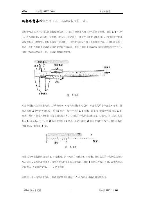
新杉本贸易教您使用日本三丰游标卡尺的方法:游标卡尺是工业上常用的测量长度的仪器,它由尺身及能在尺身上滑动的游标组成,如图2.3-1所示。
若从背面看,游标是一个整体。
游标与尺身之间有一弹簧片(图中未能画出),利用弹簧片的弹力使游标与尺身靠紧。
游标上部有一紧固螺钉,可将游标固定在尺身上的任意位置。
尺身和游标都有量爪,利用内测量爪可以测量槽的宽度和管的内径,利用外测量爪可以测量零件的厚度和管的外径。
深度尺与游标尺连在一起,可以测槽和筒的深度。
尺身和游标尺上面都有刻度。
以准确到0.1毫米的游标卡尺为例,尺身上的最小分度是1毫米,游标尺上有10个小的等分刻度,总长9毫米,每一分度为0.9毫米,比主尺上的最小分度相差0.1毫米。
量爪并拢时尺身和游标的零刻度线对齐,它们的第一条刻度线相差0.1毫米,第二条刻度线相差0.2毫米,……,第10条刻度线相差1毫米,即游标的第10条刻度线恰好与主尺的9毫米刻度线对齐,如图2.3-2。
当量爪间所量物体的线度为0.1毫米时,游标尺向右应移动0.1毫米。
这时它的第一条刻度线恰好与尺身的1毫米刻度线对齐。
同样当游标的第五条刻度线跟尺身的5毫米刻度线对齐时,说明两量爪之间有0.5毫米的宽度,……,依此类推。
在测量大于1毫米的长度时,整的毫米数要从游标“0”线与尺身相对的刻度线读出。
游标卡尺的使用用软布将量爪擦干净,使其并拢,查看游标和主尺身的零刻度线是否对齐。
如果对齐就可以进行测量:如没有对齐则要记取零误差:游标的零刻度线在尺身零刻度线右侧的叫正零误差,在尺身零刻度线左侧的叫负零误差(这件规定方法与数轴的规定一致,原点以右为正,原点以左为负)。
测量时,右手拿住尺身,大拇指移动游标,左手拿待测外径(或内径)的物体,使待测物位于外测量爪之间,当与量爪紧紧相贴时,即可读数,如图2.3-3所示。
游标卡尺的读数读数时首先以游标零刻度线为准在尺身上读取毫米整数,即以毫米为单位的整数部分。
然后看游标上第几条刻度线与尺身的刻度线对齐,如第6条刻度线与尺身刻度线对齐,则小数部分即为0.6毫米(若没有正好对齐的线,则取最接近对齐的线进行读数)。
三丰量具说明书

•
三丰卡尺需要校正吗? 三丰卡尺、三丰数显卡尺、三丰游标卡尺都需要校正。目的除了修正量具确保量测结果正确 之外,也在于避免使用不当的量具。通常卡尺超过校正标准之后,能够修复的机会不大,只 有降级使用或者报废一途。 三丰卡尺的一般用途最多有叁种,分别是外径 (外尺寸) 量测、内径(内尺寸)量测与深度量测。 可以校正者是前两项,因为深度量测部分原本就不是该量具设计的目的,只能做参考。 三丰卡尺校正的标准器是块规和阶规,但是使用块规有两大缺点。 第一、 过大尺寸没有现成块规可以使用。通常靠块规扭合,但是各个块规本身校正时有 不同的器差,使用时记录上还须加总纪录。而且要是技术不好,不但接不上多少还会伤及块 规。 第二、 块规只能作外尺寸 (大测爪) 校正,无法作内尺寸量测(小测爪)校正。 比较理想的方法是使用阶规。不过阶规很贵,六位数价格。市面上有售一种模仿阶规的 组合式校正器价格大需五万以下,看似合理方便。但其实并非正统合格的校正器。 其实,新买的三丰卡尺都需要校正。只不过一般的三丰代理商会在发货前由工程师先进行校 正工作。
三丰量表篇
• 日本三丰水平型杠杆百分表-0.01_杠杆百分表 • 日本三丰水平型杠杆百分表513系列 • 货号:513-424E,513-404E,513-404C,513-414E, 513-415E,513-464E,513-454E,513-117, 513-444E
三丰量表篇
• • • • • • • •
三丰量表篇
• • • • • 日本三丰Mitutoyo指针式百分表 2046S 0-10*0.01mm 指示表
指针式千分表 2 系列 — 标准型、0.01mm分辨率(参见第 VIII 页) 2 系列指针式千分表是三丰公司量具中最常见且应用最广泛的指针式千分表。
547-211日本三丰数显深度尺说明书

547-211日本三丰数显深度尺说明书本说明书是日本Mitutoyo三丰数字深度尺547系列其中一款,型号为547-211.这款数显深度尺是一款专门用于测试深度的数显尺,可以测量各种孔,槽,阶的深度。
其可以在电池用尽前保持原有的轨迹设置,方便下次测量,基座和测量面经过特殊处理,坚固耐用。
产品资料由“三丰计量”提供。
547-211 Mitutoyo三丰深度尺特点:• ABSOLUTE Digimatic 深度尺可在电池用尽前保持原有的原点轨迹设置。
• 安装延长杆可扩大测量范围。
• 基座底面经过硬化,研磨和抛光处理,具有很高的平面度。
• 背置活塞型指针式千分表可从正上方的垂直表盘进行读数(7231, 7237, 7238)。
• 带有SPC 数据输出(547 系列)。
Mitutoyo三丰深度尺技术参数:数显型技术参数精度: 参见性能参数(数显型号不包括量化偏差)分辨率: 0.001mm, 0.01mm, .00005"/0.001mm 或.0005"/0.01mm基座面平面度: 5μm 或2μm测头: 硬质合金球型测头或针型测头测力: 1.5N显示: LCD电池: SR44 (1 个), 938882电池寿命: 正常使用情况下约为5000 小时带表型技术参数:精度: 参见性能参数(数显型号不包括量化偏差)表盘读数值: 0.01mm 或 .001"基座面平面度: 5μm 或2μm测头: 硬质合金球型测头(测头: 7210, 7222)测力: 1.4N (2.5N: 7213, 7214, 7217, 7218)数显型功能:原点设置、调零、数据保持、数据输出、英制/公制转换(英制/公制型)警告: 低电压、计算错误数显型选件:905338: SPC 电缆(1m)905409: SPC 电缆(2m)Mitutoyo三丰深度尺性能参数:公制型:英制/公制型:。
- 1、下载文档前请自行甄别文档内容的完整性,平台不提供额外的编辑、内容补充、找答案等附加服务。
- 2、"仅部分预览"的文档,不可在线预览部分如存在完整性等问题,可反馈申请退款(可完整预览的文档不适用该条件!)。
- 3、如文档侵犯您的权益,请联系客服反馈,我们会尽快为您处理(人工客服工作时间:9:00-18:30)。
547-211日本三丰数显深度尺说明书
本说明书是日本Mitutoyo三丰数字深度尺547系列其中一款,型号为547-211.这款数显深度尺是一款专门用于测试深度的数显尺,可以测量各种孔,槽,阶的深度。
其可以在电池用尽前保持原有的轨迹设置,方便下次测量,基座和测量面经过特殊处理,坚固耐用。
产品资料由“三丰计量”提供。
547-211 Mitutoyo三丰深度尺特点:
• ABSOLUTE Digimatic 深度尺可在电池用尽前保持原有的原点轨迹设置。
• 安装延长杆可扩大测量范围。
• 基座底面经过硬化,研磨和抛光处理,具有很高的平面度。
• 背置活塞型指针式千分表可从正上方的垂直表盘进行读数(7231, 7237, 7238)。
• 带有SPC 数据输出(547 系列)。
Mitutoyo三丰深度尺技术参数:
数显型技术参数
精度: 参见性能参数(数显型号不包括量化偏差)
分辨率: 0.001mm, 0.01mm, .00005"/0.001mm 或.0005"/0.01mm
基座面平面度: 5μm 或2μm
测头: 硬质合金球型测头或针型测头
测力: 1.5N
显示: LCD
电池: SR44 (1 个), 938882
电池寿命: 正常使用情况下约为5000 小时
带表型技术参数:
精度: 参见性能参数(数显型号不包括量化偏差)
表盘读数值: 0.01mm 或 .001"
基座面平面度: 5μm 或2μm
测头: 硬质合金球型测头(测头: 7210, 7222)
测力: 1.4N (2.5N: 7213, 7214, 7217, 7218)
数显型功能:
原点设置、调零、数据保持、数据输出、英制/公制转换(英制/公制型)警告: 低电压、计算错误
数显型选件:
905338: SPC 电缆(1m)905409: SPC 电缆(2m)Mitutoyo三丰深度尺性能参数:公制型:
英制/公制型:。