宏基4736ZG拆机图解
宏基笔记本怎么拆机
宏基笔记本怎么拆机
宏基笔记本如何拆机吖?下面店铺整理了解决宏基笔记本拆机的方法,希望能帮到大家O(∩_∩)O哈哈~
宏基笔记本拆机方法
翻过来背面先取下电池
拆掉背面板螺丝,取下盖板
摘除取下内存、硬盘、光驱
将背面能看见的螺丝和排线都拆掉,螺丝基本都差不多大小,只需把不一样的做好位置标记即可
螺丝和排线拆掉以后,翻到正面取键盘,在ESC键、F4、F8、F12、TAB、PGUP位置有小卡子,用工具挨个往上顶,并在翻开键盘时注意下面的排线,不要硬拽,往上轻轻掰开卡子就出来了取掉键盘下面的螺丝和排线
不要用铁质的东西撬开C面,这样很容易撬裂,可以用是卡板或者指甲,慢慢打开,注意观察有没有线或者螺丝之类连着没有拔掉数据线、排线,拆下螺丝,取下主板
打开风扇,清理灰尘,最好不要拆铜管,会导致电脑工作异常的,高手可以尝试。
拆机原则先观察再动手,螺丝起对角
最后,按照拆机步骤仔细装机,注意不要落下零件,装好后检查一下,开机测试。
注意事项
千万不要使用非专业工具拆机。
笔记本Acer拆机记
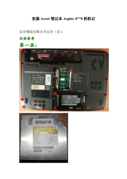
宏基Acert笔记本Aspire 4**0拆机记总步骤按层数分为五步(层):
仅供参考
第一层:
有三种螺丝,上方中间电池下方三个一组为一种,下面盖下两个坚排的为一种。
其余为一种。
第二层:
这一层首先扣下开关键面板,用手指就行。
再拿下键盘与主机相连的数据线就可取下。
第三层:
很长,要从后边开始拆起,慢慢拆。
沿左边沿用手指把可扣开的扣开,再把蓝色的数据线拆开(小心)。
右边和下边要用尖的工具搓一下(图上标为三角地方),它就弹开整个就拆开。
拆下来正反面:
第四层:
第五层:
读卡器:。
宏基4736ZG拆机现用图解
详细流程:1:先将本本周边所有外配件拆除,如电源插头、鼠标等,特别需要注意的是SD卡槽上的防尘片;2:拆下底盖下的所有配件,如电池、内存、硬盘、无线网卡,从无线网卡上拆下的是唯一的2 X 3螺丝3:将底盖所有螺丝拆下,记住各螺丝位置,仅两种类型的螺丝,深槽是长的,浅槽是中长的,电池座下的螺丝最短2.5 X 34:将光驱从侧边抠出;5:使用废信用卡或吉它弹片将喇叭盖拆下,方法是找到机器侧面的电源插头与电源显示灯处的边缝用弹片撬开,顺着键盘ESC键到DEL处的边缝将喇叭盖撬开,将喇叭盖拿出,拆时注意力度需要适中;6:拆下键盘,注意键盘的软PCB排线及插座,再将触摸板、功能键排线拔下;7:MIC、摄像头显示屏、喇叭连接线8:将喇叭条拆下,固定喇叭的是2.5 X 3 短螺丝2颗,顺便清理9:将无线网卡到显示面板的连接线拆出10:要将显示屏板及相连的主机上盖拆下来,必须先拆开以下两颗螺丝,然后使用废信用卡或吉它弹片将底盖与上盖边缝撬开分离,分离后轻轻将显示屏及主机上盖拿起,必须注意上盖塑料极薄,切不可蛮力将显示板与上盖合起,以防折断。
11:拿掉上盖后剩下的就是底盖及主板,此时必须先将主板与底盖的引线拆下,仅有猫跟右侧USB引线12:拆除主板上唯一的2.5 X 3 螺丝,顺着光驱出口方向将主板从底盖中分离出来13:从主板上先将风扇的导线拔下,再拧开两颗固定风扇的螺丝,再从风扇上把四颗小螺丝拆下便可完全的清理风扇14:拆下散热片后将散热片内的污物用水冲洗干净,并用风筒吹干,注意别被风筒吹导热管时传过来的高温烫到,清理散热片后别忘了给主板进行清扫,主板上的灰也不会少的,最后还要给CPU及GPU添加优质导热硅脂。
15:清扫底盖的通风孔,以利于通风acer 4736ZG拆机清灰教程RT。
今天早起看到有活动,拆机神马的送螺丝刀,正好丢失了一套,那参加一下吧,哈哈。
我的4736ZG购于09年,虽然说帮同学们拆过很多次,但自己这本子这次却是第一次拆,下面上图先说明:图中画圆圈圈的就是要拆掉的螺丝,箭头就是表示向什么方向推下面是后面的图图上红圈里面的就是要拆掉的螺丝,当然电池下面也有(有一个可能会被一张条形码贴住),拿掉电池就可以看到了,全拆了光驱这样就可以拉出来(当然首先要完成上面的拆螺丝步骤)硬盘居然没有螺丝固定。
宏碁TM_4730_4630系列计算机拆解教程
TravelMate 4730/4732Series Extensa 4630 SeriesDisassembly Instruction elMachine Disassembly and ReplacementThis chapter contains step-by-step procedures on how to disassemble the notebook computer formaintenance and troubleshooting.Disassembly RequirementsTo disassemble the computer, you need the following tools:•Wrist grounding strap and conductive mat for preventing electrostatic discharge•Flat screwdriver•Philips screwdriver•Plastic flat screwdriver•Plastic tweezersNOTE: The screws for the different components vary in size. During the disassembly process, group the screws with the corresponding components to avoid mismatch when putting back the components.General InformationPre-disassembly InstructionsBefore proceeding with the disassembly procedure, make sure that you do the following:1.Turn off the power to the system and all peripherals.2.Unplug the AC adapter and all power and signal cables from the system.3.Place the system on a flat, stable surface.4.Remove the battery pack.Disassembly ProcessThe disassembly process is divided into the following stages:•External module disassembly•Main unit disassembly•LCD module disassemblyThe flowcharts provided in the succeeding disassembly sections illustrate the entire disassembly sequence.Observe the order of the sequence to avoid damage to any of the hardware components. For example, if you want to remove the main board, you must first remove the keyboard, then disassemble the inside assembly frame in that order.External Module Disassembly ProcessExternal Modules Disassembly FlowchartThe flowchart below gives you a graphic representation on the entire disassembly sequence and instructs you on the components that need to be removed during servicing. For example, if you want to remove the main board, you must first remove the keyboard, then disassemble the inside assembly frame in that order.Removing the Battery Pack1.Turn computer over.2.Slide the battery lock/unlock latch to the unlock position.3.Slide and hold the battery release latch to the release position (1), then slide out the battery pack from the mainunit (2).12Removing the SD dummy card1.Push the SD dummy card all the way in to eject it.2.Pull it out from the slot.Removing the NewCard dummy card1.Push the NewCard eject button to eject it, then push it all the way in to eject the NewCard dummy.2.Pull it out from the slot.Removing the Lower Covers1.See “Removing the Battery Pack”2.See “Removing the SD dummy card”3.See “Removing the NewCard dummy card” .4.Loosen the five captive screws in the Memory, HDD, and WLAN bays as shown.5.Carefully open the memory cover.6.Remove the HDD cover as shown. HDD Cover Memory CoverWLANCover7.Remove the WLAN cover as shown.Removing the DIMM Modules1.See “Removing the Battery Pack” .2.Remove the Memory Module cover See “Removing the Lower Covers” .3.Push out the release latches on both sides of the DIMM socket to release the DIMM module.4.Remove the DIMM module.5.Repeat steps for the second DIMM module.Removing the WLAN Module1.See “Removing the Battery Pack” .2.Remove the WLAN cover. See “Removing the Lower Covers”3.Remove the adhesive tape and disconnect the antenna cables from the WLAN board.4.Move the antenna cables away and remove the two screws on the WLAN board to release the WLAN board.Step Size Quantity Screw Type WLAN Module M2*3 (NL)25.Detach the WLAN board from the WLAN socket.NOTE: When re-attaching the antenna to the WLAN board, make sure the cables are arranged under the WLAN bracket.Removing the Hard Disk Drive Module1.See “Removing the Battery Pack”.2.Remove the HDD cover, See “Removing the Lower Covers”e the mylar tab to slide and lift up the hard disk drive module to remove.NOTE: To prevent damage to device, avoid pressing down on it or placing heavy objects on top of it.4.Remove the HDD holder by easing the sides outward to clear the carrier.5.Remove the four screws securing the hard disk to the carrier.6.Remove the HDD from the carrier.StepSize QuantityScrew TypeHDD Carrier M3*3.5 (NL)4Removing the Optical Drive Module1.See “Removing the Battery Pack” .2.Remove the Memory cover. See “Removing the Lower Covers”3.Remove the screw securing the ODD module.ing a screw driver, push the ODD module through the chassis and pull to remove it from the main unit.StepSize QuantityScrew TypeODD Module M2.5*5(NL)15.Remove the three screws securing the ODD bracket and remove the ODD bracket from the ODD module.6.Insert a pin in the eject hole of the ODD to eject the ODD tray.7.Press down on the locking catch to release the ODD cover and remove.Step Size Quantity Screw Type ODD Bracket M2*3 (NL)3Main Unit Disassembly Process Main Unit Disassembly FlowchartRemoving the Switch CoverCAUTION: Using tools to remove the Switch Cover may cause damage to the outer casing. It isrecommended that only fingers are used to remove the Switch Cover.1.See “Removing the Battery Pack”2.Locate and remove the five securing screws as shown.3.Turn the computer over and open the LCD module fully to expose the Switch Cover.IMPORTANT:The LCD module must be fully open in the horizontal position to remove the switch cover.4.Lift the Switch Cover as shown, rightside first.5.Lift the Switch Cover clear of the chassis.StepSizeQuantity Screw Type Switch CoverM2.5*35Removing the Keyboard1.See “Removing the Battery Pack”2.See “Removing the Switch Cover”3.Remove the two screws securing the keyboard to the upper case.4.Lift the keyboard as shown to remove from the chassis.5.Turn the keyboard over and pull back the securing latch to release the FFC.StepSizeQuantity Screw TypeKeyboard M2*326.Remove the keyboard from the chassis.Removing the Power Board1.See “Removing the Battery Pack” .2.See “Removing the Keyboard” .3.Disconnect the Power Board cable from the mainboard.4.Remove the two securing screws from the Power Board.NOTE: The left hand securing screw is shared by the eKey Board.Removing the Launch Board1.See “Removing the Battery Pack” .2.See “Removing the Keyboard”3.Disconnect the Launch Board cable from the mainboard.4.Remove the two securing screws from the Launch Board.NOTE: The right hand securing screw is shared by the Power Board.StepSizeQuantityScrew TypePower BoardM2*32Removing the Antenna1.See “Removing the WLAN Module”2.Remove the Antenna Cables from the securing guides as shown.3.Turn the computer over, remove the adhesive tape and disconnect the FCC cables to expose the antennacables underneath.Step SizeQuantity Screw TypeLaunch BoardM2*324.Secure the FFC cable out of the way using the adhesive tape.5.Turn the computer over and push the cables through the underside of the chassis.6.Turn the computer over, and remove the cable from the mainboard as shown.7.Remove the Antenna Cables from the housing well as shown.NOTE: Place the cables to one side to avoid damage.Removing the LCD Module1.Remove the Battery Pack. See “Removing the Battery Pack”2.Remove the Lower Covers. See “Removing the Lower Covers”.3.Remove the WLAN Module. See “Removing the WLAN Module”4.Remove the Antenna. See “Removing the Antenna”5.Remove the two securing screws from the bottom of the chassis.6.Turn the computer over. Disconnect the LCD cable from the top panel.StepSizeQuantityScrew TypeLCD ModuleM2.5*8(NL)27.Remove the four securing screws (two on each side) connecting the LCD module.8.Carefully remove the LCD module from the chassis.StepSizeQuantity Screw TypeLCD Module (Red callout)M2.5*92LCD Module (Blue callout)M2.5*52Removing the Upper Cover1.See “Removing the Battery Pack” .2.See “Removing the LCD Module” .3.Turn the computer over. Remove the sixteen screws on the bottom panel.Step Size Quantity Screw Type Upper Cover M2.5x9164.Turn the computer over and disconnect the seven cables from the mainboard as shown.Disconnect A as shown. If necessary, remove FFC Gbefore beginning.Pull back the securing strip and disconnect B and C as shown.Remove the antenna cables from the housing andpull back away from the upper cover.Release the securing latches and disconnect E asshown.BE FG ADCBC5.Remove the single screw on the top panel.Disconnect the Power Board FFC (E) first beforeremoving FFC D. Pull back the locking latches torelease D.Release the securing latches and disconnect F asshown.Release the securing latches and disconnect G as shown.Step Size Quantity Screw TypeUpper Cover M2.5*9 (NL)16.Grasp the top left corner first and pry the cover off.7.Continue moving from left to the right corner and pry it off the lower cover.8.Move to the bottom right corner and pry it up.9.The Upper Cover can now be removed from the lower base.Removing the Finger Print Reader1.See “Removing the Upper Cover”2.Remove the securing screw from the Finger Print Reader board, and ensure the FFC is free of the upper cover.Step Size Quantity Screw Type finger print reader M2.5*3 (NL)13.Remove the board bracket from the Upper Cover.IMPORTANT:Do not throw away the Bracket Pad. Remove and replace on new bracket.Bracket Pading your fingers, gently lift the Finger Print Reader board from the Upper Cover.5.Pull the Finger Print Reader FFC through the touchpad bracket taking care not to fray the cable.Removing the Touch Pad Bracket1.See “Removing the Upper Cover”2.Peel back the Finger Print Reader FFC to expose the Touch Pad connector.3.Disconnect the Touch Pad FFC from the Touch Pad board.4.Lift up the covering and remove the securing screw.Step Size Quantity Screw Type Touch Pad Bracket M2.5*3 (NL)25.Remove the Touch Pad bracket.IMPORTANT:The Touch Pad cannot be removed individually. To replace the Touch Pad, replace the entire Upper Cover.Removing the Left Speaker Module1.See “Removing the Upper Cover”2.Peel back the adhesive strip to expose the speaker cabling.3.Remove the two securing screws.4.Grasp both ends of the mylar cover and carefully pull back to expose the speaker cable.StepSizeQuantity Screw TypeLeft SpeakerModule M2.5*3 (NL)2Removing the Right Speaker Module1.See “Removing the Upper Cover”2.Remove the two securing screws from the speaker module.3.Grip the Speaker Module and remove.StepSizeQuantity Screw TypeRight SpeakerModule M2.5*3 (NL)22.Remove the adhesive strip to expose the Bluetooth cable.3.Disconnect the bluetooth cable as shown.4.Lift the corner of the module up, then grasp to remove.2.Disconnect the RJ-11 cable as shown.3.Remove the two (2) securing screws.4.Lift the module and remove from the lower cover as shown.StepSize QuantityScrew TypeModem Module M2*3 (NL)2Removing the Mainboard1.See “Removing the LCD Module” .2.See “Removing the Upper Cover” .3.See “Removing the Modem Module”4.Turn the lower base over on a clean surface, and disconnect the DC-IN cable as shown.IMPORTANT:Ensure the cable can easily pass through the lower cover during mainboard disassembly.5.Turn the base rightside up, and disconnect the bluetooth cable from the bottom right of the mainboard asshown.6.Remove the two securing screws from the Mainboard.7.Lift the mainboard to expose the DC-IN jack and USB cable.8.Remove the DC-IN jack and USB cable as shown.StepSize Quantity Screw TypeMainboard M2.5*9 (NL)Green Call out 1Mainboard M2.5*3 (NL)Red Call out 19.Grasp the mainboard by both sides and pivot upwards to remove.CAUTION: Ensure the I/O ports at the bottom of the mainboard are clear of the bottom base to prevent damage to the mainboard.1.Remove the mainboard. See “Removing the Mainboard” .2.Remove cable from the USB board.3.Remove the two securing screws from the USB board and lift clear of the chassis.1.See “Removing the Mainboard”2.Disconnect the RJ-11 cable from the modem module.3.Grasp the cable and gently lift it out of the housing well.4.If necessary insert tweezers in the RJ-11 jack, lift the RJ-11 jack from the base.Removing the Thermal Module1.See “Removing the Battery Pack” .2.See “Removing the LCD Module”3.See “Removing the Upper Cover”4.See “Removing the Mainboard”5.6.Disconnect the fan module cable from mainboard.Step Size Quantity Screw Type CPU ThermalModule(red call out)M2*6.54VGA ThermalModule(blue call out)M2*347.Lift the Thermal Module clear of the Mainboard.Removing the CPU1.See “Removing the Battery Pack”2.See “Removing the Upper Cover” .3.See “Removing the Mainboard” .4.See “Removing the Thermal Module”.ing a flat screwdriver, turn the CPU socket latch counter-clockwise 180° to release the CPU.6.Lift the CPU clear of the Mainboard.Removing the VGA Module1.Remove the mainboard. See “Removing the Mainboard” .2.Remove the two securing screws from the VGA Module.3.The VGA module lifts automatically from the mainboard. Remove the VGA Module as shown.StepSizeQuantity Screw TypeVGA Module M2*4-NI (NL)2LCD Module Disassembly Process LCD Module Disassembly FlowchartRemoving the LCD Bezel1.Remove the LCD module. See “Removing the LCD Module” .2.Remove the two upper and two lower bezel screw caps. Remove the four securing screws from the LCDmodule.3.Lift up the bezel, topside first, and remove it from the LCD Module.Step SizeQuantity Screw TypeLCD Bezel M2.5*5 (NL)42.Remove the securing tapes from the left and right sides of the Inverter board as shown.3. Remove the two securing screws from the Inverter board and lift the board clear of the LCD Module.4.Remove the Inverter Board from the LCD Module.StepSize Quantity Screw TypeInverter Board M2.5*6 (NL)22.Disconnect the Camera Module cable as shown.3.Remove the two securing screws from the Camera Module bracket.Step Size Quantity Screw Type Camera ModuleM2*3 (NL)2。
宏基4736ZG拆机图解
详细流程:1:先将本本周边所有外配件拆除,如电源插头、鼠标等,特别需要注意的是SD卡槽上的防尘片;2:拆下底盖下的所有配件,如电池、内存、硬盘、无线网卡,从无线网卡上拆下的是唯一的2 X 3螺丝3:将底盖所有螺丝拆下,记住各螺丝位置,仅两种类型的螺丝,深槽是长的,浅槽是中长的,电池座下的螺丝最短2.5 X 34:将光驱从侧边抠出;5:使用废信用卡或吉它弹片将喇叭盖拆下,方法是找到机器侧面的电源插头与电源显示灯处的边缝用弹片撬开,顺着键盘ESC键到DEL处的边缝将喇叭盖撬开,将喇叭盖拿出,拆时注意力度需要适中;6:拆下键盘,注意键盘的软PCB排线及插座,再将触摸板、功能键排线拔下;7:MIC、摄像头显示屏、喇叭连接线8:将喇叭条拆下,固定喇叭的是2.5 X 3 短螺丝2颗,顺便清理9:将无线网卡到显示面板的连接线拆出10:要将显示屏板及相连的主机上盖拆下来,必须先拆开以下两颗螺丝,然后使用废信用卡或吉它弹片将底盖与上盖边缝撬开分离,分离后轻轻将显示屏及主机上盖拿起,必须注意上盖塑料极薄,切不可蛮力将显示板与上盖合起,以防折断。
11:拿掉上盖后剩下的就是底盖及主板,此时必须先将主板与底盖的引线拆下,仅有猫跟右侧USB引线12:拆除主板上唯一的2.5 X 3 螺丝,顺着光驱出口方向将主板从底盖中分离出来13:从主板上先将风扇的导线拔下,再拧开两颗固定风扇的螺丝,再从风扇上把四颗小螺丝拆下便可完全的清理风扇14:拆下散热片后将散热片内的污物用水冲洗干净,并用风筒吹干,注意别被风筒吹导热管时传过来的高温烫到,清理散热片后别忘了给主板进行清扫,主板上的灰也不会少的,最后还要给CPU及GPU添加优质导热硅脂。
15:清扫底盖的通风孔,以利于通风acer 4736ZG拆机清灰教程RT。
今天早起看到有活动,拆机神马的送螺丝刀,正好丢失了一套,那参加一下吧,哈哈。
我的4736ZG购于09年,虽然说帮同学们拆过很多次,但自己这本子这次却是第一次拆,下面上图先说明:图中画圆圈圈的就是要拆掉的螺丝,箭头就是表示向什么方向推下面是后面的图图上红圈里面的就是要拆掉的螺丝,当然电池下面也有(有一个可能会被一张条形码贴住),拿掉电池就可以看到了,全拆了光驱这样就可以拉出来(当然首先要完成上面的拆螺丝步骤)硬盘居然没有螺丝固定。
宏基(acer)Aspire拆机
宏基(acer)Aspire拆机教程我的电脑是宏基Aspire系列的,到现在刚好用了一年,平时在学校用的时候都在下面放一个散热架,但是寒假回家之后发现不用散热架的电脑温度过高,鲁大师经常对CPU温度报警。
我只能用一会歇一会,就连游戏都不敢玩,今天下午跟朋友玩了会游戏电脑居然死机了,对于这个现象我有点忍无可忍了。
由于电脑已经过了保修期,去客服那清理灰尘已经不是免费的了,我于是就决定自己动手,上百度搜索了一下我这个型号电脑的拆机教程,上面只是给出了一些泛泛的指导,当时我还以为拆机不是很困难,就找了几个不同型号的螺丝刀开始了我的拆机尝试,但是不做不知道,一做下一跳,在拆机过程中出现的问题远比网上说得多。
有N个螺丝和N+1条排线,一不小心可能就能把电脑拆坏,还好在我小心翼翼的努力下经过了一个多小时的工作终于把电脑的所有零件都拆下来清理了一下,重新装起来之后电脑还能正常工作,说明我的这次很有风险的尝试还算成功。
下面就把我的拆机过程详细的介绍给大家。
1.这是拆机前的样子2.按照图中画圆圈标定的螺丝位置先拆下背面的所有螺丝和保护盖(注:背面一共6个较小的螺丝,13个较大的螺丝其中有几个是固定保护盖的,在这里没有画出)3.拆下硬盘和无线网卡(无线网卡上有两个固定的螺丝必须先拆下,并且一黑一白两根导线要轻轻地从上面摘下,这两根导线连接着屏幕)4.拆下键盘先找到键盘上两个卡扣,用小螺丝刀将卡扣压进卡槽,轻轻向上搬动最上排的按键就可以轻松地把键盘拆下但是不要太用力,因为键盘下边连着排线,如果用力太大会将排线扯坏,从此步之后会经常遇到排线拆卸。
拆卸排线时只要两手分别用一个螺丝刀同时轻轻地将压住排线的卡扣向外搬动,然后将排线向外轻轻抽出就可以了,以后对于的处理方法也一样。
接下来将标记处的排线都拆下5.拆下靠近屏幕的开机键以及多媒体键区域由于背面的螺丝已经全部拆除,所以现在这个区域已经没有螺丝固定所以只要沿着这个区域的外延用小螺丝刀轻轻撬动就可以轻松的将其拆下,不过值得注意的是这个键区仍有一个排线,应用上面介绍的方法就可以将其拆下6。
acer4745拆机图
拆解第一步:准备工作。
先要准备小号梅花起子一个,废弃银行卡1-2张,小刷子一把,硅脂若干,全开干净白纸一张。
把白纸铺在台面上,笔记本电脑就放在白纸上面。
使用白纸目的是干净,拆下的螺丝在白纸上更醒目,不会丢失。
拆解第二步:卸载电池。
要拆机先卸电池,这是拆机最关键的一步。
不拆电池,万一拆机过程中损坏硬件划不来:拆解第三步:拆后盖。
后盖拆卸是比较简单的,但是也要注意,后盖有5个塑料暗扣,扳坏一个都会造成很大的麻烦。
先卸下五颗后盖固定螺丝:再用银卡插入连接缝里,往右边轻轻的刷开暗扣:注意:后盖右边还有四格暗扣,硬扳一样会版坏。
要右手轻按右边,左手轻提左边往外拉出:打开后盖,硬盘、内存、无线网卡和显卡散热管就暴露无遗了。
注意,显卡左边的螺丝就是光驱固定螺丝,旁边是电源线插座。
左上角全拆卸底面全貌:拆解第四步:拆硬盘。
固定硬盘有两颗螺丝,拧下后即可拉出:一直把插头从固定的插座上拉出来。
这就是拆下来的硬盘,是日立的:拆解第五步:拆内存。
再来看看内存,把内存两边的固定扣往两边扳开,内存就会自动弹起,然后抽出即可。
安装时,插入内存,按下即可。
有两个内存插槽,安装的是单条2G,加一条2G就可以升级为双通道4G内存。
右下角是抽出的内存,三星的:拆解第六步:光驱拆卸。
光驱拆卸十分简单,在第三步最后一张图中,拧下光驱固定螺丝,即可抽出光驱。
拆解第七步:卸载无线网卡。
无线网卡只有一颗螺丝,卸下即可。
注意拔下两根连线,直接拔下来就行。
另外,要全拆,还要拔下光驱固定螺丝边上的电源插头。
拆解第八步:键盘拆卸。
底面拆完后,再要继续拆,就要把D面所有固定螺丝,包括电池仓和硬盘仓里的螺丝全部拧下来,再到C面拆键盘。
过去的笔记本电脑拆卸键盘十分麻烦,现在简单多了。
只要把键盘上部的几个固定栓用银卡顶进去,键盘就会弹起来。
扳起黑色卡扣,数据线自然滑出。
安装时也是插入数据线后再按下卡扣:拆下的键盘两面是这样的:拿掉键盘,就可以看到键盘基座。
左上角就是散热器的位置,从这里可以看出散热器积尘情况,需不需要清理灰尘:接下来,只要拧下基座固定螺丝,再用银卡刷开基座塑料扣,就可以拿下基座了。
笔记本屏幕拆机教程-acer
工欲善其事必先利其器。
螺丝刀绝对是电脑玩家必备,相信各位手中也不会少。
刀头各种各样,其实很多很少用到,但是万一需要的时候又真是没有不行。
比如任天堂专用的Y字形等等。
对于拆笔记本来说,其实必备的也就是几种尺寸的十字和一个一字(主要做撬棍用,选薄的,在保证强度前提下越薄越方便。
我用的专门的弯头)镊子在对付某些细小部件时候有很好的效果,但不是必须导热硅脂,用于CPU和散热器之间的导热。
如果不拆开CPU散热器则不需要。
我用的是北极银5,12克装。
Amazon价格20美金。
另外除了所有的工具之外,还需要一个至少一平方米的操作空间,因为会有很多零件需要摆放,千万不要乱丢,否则你会后悔的。
===============================正式开工,我这里就以我自己的ACER 4736z为例子进行。
首先拔出所有的连接线缆并退出读卡器内的卡片。
然后将笔记本翻到D面。
拆除电池。
在地毯房里操作,容易有静电,安全考虑最好先去洗个手,水流会带走电荷。
冬天尤其必要。
卸掉所有可以拆卸的盖板。
部分厂商可能会在这些上面贴上易碎贴,作为保修凭证。
如果不想失去保修的话,电吹风伺候吧。
手上一定要小心。
我自己是懒得做的,无所谓。
自觉RP还可以,从来不保修。
一般情况下,所有盖板的螺丝都是固定在盖板上的,避免丢失。
如果没有固定的,需要妥善保管。
最好和盖板放在一起。
无线网卡上,一般会连接有天线,有条件记得拍照记下接线位置,避免接错。
内存部分都是有下图圈中这样的卡扣卡住。
按照箭头方向推开卡扣就行了。
推开之后内存会自动弹起,顺势拔出即可。
硬盘部分则不尽相同,有各种的锁定方式,有的还需要再拆卸螺丝,不过大多提供塑料弹片便于拖拽。
按照指引拆卸吧。
对于我的笔记本,往箭头方向拖拽,使框中金手指部分脱离即可。
无线网卡,内存,硬盘拆下后妥善放置。
回来看拆下部件之后的D面,下一步的工作是拆除该面所有螺丝。
找来一张白纸,对应D面螺丝孔位,在纸上相应位置画下小圈,不需要十分精确。
笔记本拆解全程解读
笔记本拆解全程解读最近天气越来越热,笔记本的温度也越来越高,尤其是运行大型程序的时候,趁今天有空,把笔记本拆开清理了一下,顿时觉得清爽了不少。
顺便写个拆解笔记,给想要清理笔记本的朋友一个参考。
本次拆解的是宏碁Aspire 1551,不过其他机型也大同小异,尤其是拆解顺序,基本一致。
初次拆解,比较小心谨慎,先贴个大卸八块的图(这次主要是为了清理灰尘,所以没有把屏幕拆下来。
如果想拆也很简单,把几个螺丝拧下来就可以了):拆解用到的工具如下:从左到右依次是:洗耳球、万用螺丝刀(带磁性最好)、刷子、小螺丝刀、镊子。
前期准备:洗洗手、晾干、找个金属物体(如铁栏杆、楼梯扶手……)双手摸一摸(除去静电)。
拆解步骤:1、断开笔记本电源,卸下电池。
2、笔记本背面朝上,拆下中间的小盖子。
拆解后如图:此时可以看到笔记本的内存条、硬盘。
现在的笔记本一般有两个内存插槽,想扩展内存的话自己买个与原内存条同样规格的内存条,插在另外一个插槽,按下卡住即可,一般不会有问题,不用找个奸商花几十块钱装一下。
内存条特写3、拆下内存条和硬盘。
内存条:两边有两个卡扣,朝两边掰开,内存条会自动弹起,拔出即可。
安装的时候,先将内存条完全插入卡槽,再按下去让两个卡扣卡住即可。
硬盘:硬盘周围可能会有固定螺丝,先把螺丝拆下,然后硬盘一端会有专门拉出硬盘的塑料片,顺着硬盘方向小心拉出即可。
因为另外一端是金手指,所以拉出的时候角度越小越好。
内存条和硬盘要放好,这两个东西直接影响到电脑的运行。
拆解后:4、把后盖上所有的螺丝拆下,一定要是所有!!!还有网卡及其连接线。
(应该是无线网卡,不是很确定。
连接下直接连着屏幕,所以不用拆下,只要从线槽中拔出来即可)螺丝如图中黄色标记:5、翻转笔记本,把笔记本正面朝上,露出键盘。
6、拆下键盘,把键盘接口从插槽中拔出。
键盘周围会有很多卡扣,一般从上端(靠近屏幕一端)将卡扣一一推回,键盘即可弹起,然后慢慢拔出。
键盘容易弯曲,所以虽然卡扣很多,也不难拆下。
宏基4743G拆机图解
首先,要把背面的螺丝都拆掉。
一定要码好螺丝,别乱放。
不过这几颗螺丝,没啥区别,可以混用.. 有差异的,一定要记好位置。
摘开盖硬盘的那个盖子后,里边还有三颗螺丝,也要拆掉,那样我们就能把主板拿下来了。
器材:魅族MX(16GB)[魅族手机]时间:2012-01-14 14:02:55+08:00 快门:1/6 光圈:F/2.2 焦距:3毫米感光度:276画圈处是需要叉掉的小螺丝。
电池槽下边那两颗是键盘的螺丝,在下边单颗螺丝,是光驱的螺丝,拆掉后,光驱就可以拿下来了。
螺丝拆完后,需要把壳撬开,慢慢撬,别着急。
没指甲,可以借助工具。
然后翻到正面,拆键盘。
这张拍的有点模糊了..器材:魅族MX(16GB)[魅族手机]快门:1/7 光圈:F/2.2 焦距:3毫米感光度:227 我们需要把键盘上的卡扣,按下去,如图器材:魅族MX(16GB)[魅族手机]快门:1/7 光圈:F/2.2 焦距:3毫米感光度:186这种卡扣(可以前后推的,等键盘拆掉后,反过来自己看看就明白了),每种笔记本电脑键盘都会有。
我们拆机过程中,需要把ESC、F4、F8、F12、Del处的五个卡扣推掉。
当五个卡扣都推掉后,键盘上册就会微微翘起(背面的键盘螺丝一定要摘掉,否则翘不起来)。
另外还需要注意,在Tab和Pg Up键出,分别各有一个固定卡扣。
这时我们只需要稍微用力,倾斜一下,键盘就下来了。
注意动作幅度不要太大,键盘后边还连着排线,不要把排线弄断。
键盘的排线,是被扣住了,用指甲向上一扣,就像开洗发水的盖一样键盘的排线就出来了。
器材:魅族MX(16GB)[魅族手机]快门:1/16 光圈:F/2.2 焦距:3毫米感光度:138 然后我们就看到键盘下边的玄机了..器材:魅族MX(16GB)[魅族手机]时间:2012-01-14 14:20:51+08:00 快门:1/11 光圈:F/2.2 焦距:3毫米感光度:127另外,这里还有个螺丝需要摘掉,就是画圈那里,否则的话,上边这个壳可是拿不掉的。
- 1、下载文档前请自行甄别文档内容的完整性,平台不提供额外的编辑、内容补充、找答案等附加服务。
- 2、"仅部分预览"的文档,不可在线预览部分如存在完整性等问题,可反馈申请退款(可完整预览的文档不适用该条件!)。
- 3、如文档侵犯您的权益,请联系客服反馈,我们会尽快为您处理(人工客服工作时间:9:00-18:30)。
详细流程:
1:先将本本周边所有外配件拆除,如电源插头、鼠标等,特别需要注意的是SD卡槽上的防尘片;
2:拆下底盖下的所有配件,如电池、内存、硬盘、无线网卡,从无线网卡上拆下的是唯一的2 X 3螺丝
3:将底盖所有螺丝拆下,记住各螺丝位置,仅两种类型的螺丝,深槽是长的,浅槽是中长的,电池座下的螺丝最短2.5 X 3
4:将光驱从侧边抠出;
5:使用废信用卡或吉它弹片将喇叭盖拆下,方法是找到机器侧面的电源插头与电源显示灯处的边缝用弹片撬开,顺着键盘ESC键到DEL处的边缝将喇叭盖撬开,将喇叭盖拿出,拆时注意力度需要适中;
6:拆下键盘,注意键盘的软PCB排线及插座,再将触摸板、功能键排线拔下;
7:MIC、摄像头显示屏、喇叭连接线
8:将喇叭条拆下,固定喇叭的是2.5 X 3 短螺丝2颗,顺便清理
9:将无线网卡到显示面板的连接线拆出
10:要将显示屏板及相连的主机上盖拆下来,必须先拆开以下两颗螺丝,然后使用废信用卡或吉它弹片将底盖与上盖边缝撬开分离,分离后轻轻将显示屏及主机上盖拿起,必须注意上盖塑料极薄,切不可蛮力将显示板与上盖合起,以防折断。
11:拿掉上盖后剩下的就是底盖及主板,此时必须先将主板与底盖的引线拆下,仅有猫跟右侧USB引线
12:拆除主板上唯一的2.5 X 3 螺丝,顺着光驱出口方向将主板从底盖中分离出来
13:从主板上先将风扇的导线拔下,再拧开两颗固定风扇的螺丝,再从风扇上把四颗小螺丝拆下便可完全的清理风扇
14:拆下散热片后将散热片内的污物用水冲洗干净,并用风筒吹干,注意别被风筒吹导热管时传过来的高温烫到,清理散热片后别忘了给主板进行清扫,主板上的灰也不会少的,最后还要给CPU及GPU添加优质导热硅脂。
15:清扫底盖的通风孔,以利于通风
acer 4736ZG拆机清灰教程
RT。
今天早起看到有活动,拆机神马的送螺丝刀,正好丢失了一套,那参加一下吧,哈哈。
我的4736ZG购于09年,虽然说帮同学们拆过很多次,但自己这本子这次却是第一次拆,下面上图先说明:图中画圆圈圈的就是要拆掉的螺丝,箭头就是表示向什么方向推
下面是后面的图
图上红圈里面的就是要拆掉的螺丝,当然电池下面也有(有一个可能会被一张条形码贴住),拿掉电池就可以看到了,全拆了
光驱这样就可以拉出来(当然首先要完成上面的拆螺丝步骤)
硬盘居然没有螺丝固定。
按箭头方向推就可以把硬盘拿下来啦
内存条在这里,把上图红方框里的两个往外面掰就可以让内存条弹起来啦,然后就可以拿下来了。
装上去的话就是先斜着插上内存条再掰开两边的铁架子,按平内存条,松开手就可以啦(描述不好,实际拆了一次内存条之后就肯定会装上去了)
把笔记本正过来,如上图打开,用银行卡什么的方便点,当然有手指甲更好
这个也是,键盘是一块板,可以拿下来的,至于先拿下喇叭那个盖板还是先拿下键盘。
我试了一下貌似都可以,不过这里比较紧,要耐心
注意键盘现在还和主板连着,不能马上就扯下来。
具体看下图
如图,按图上把最大的那个排线拿下(这张图忘记画了,本帖最后有特写图),就可以把键盘完全拿下来了,另外两个排线是触控板的,当然现在也松开吧
拿下键盘之后如上图,再按图中拆掉螺丝,还有一个排线,(喇叭盖拿下来之后)每个喇叭旁边面也有一颗螺丝,也拿下来。