
Pspice使用指南
(三)、执行模拟(仿真计算) 当一切设置完之后,便可以启动分析程序[PSpice]对电路进行分析。选择 Analysis=>Simulate,或单击常用工具栏中相应的按钮,或按快捷键 F11,可以启动 (自动建立电路网络表(Analysis=>Create Netlist),自动进行电路检查 (Analysis=>Electrical Rule Check))。 在分析过程中,会显示其运行窗口,如图 16-9。如在电路中发现错误,会在运行中用 红色文字显示,如图 16-10。选择 Analysis=>Examine Output 可查看错误原因。
找到所需的电路符号后,单击该符号,则该符号的名称便显示在 Part Name 文本框中, 同时 Description 文本框中出现一行文字,说明该符号的含义。单击[Place]键可取出 元件但不关闭对话框;单击[Place&Close]键取出并关闭对话框;也可双击符号名列表 中某一符号将其取出。 在本例中不仅需要取出三个电阻、两个直流电压源和一个接地端,还要取出符号 PARAM 将电阻的阻值定义为全局变量,因本例是一个以电阻阻值为扫描变量的例子。
Probe 是 PSpice 对分析结果进行波形处理、显示和打印的有效工具,Probe 可以给出 波形各点的精确数据,可以迅速找到波形的极大、极小值点及其他特殊点,给波形加 标注,按所需添加坐标设置,还可以保存波形显示屏幕等。它有被称为“软件示波器”。
有两种方法启动 Probe 程序:
(1)在[Schematics]中,Analysis=>Probe Setup => Auto-run Option 设置为 Automatically…时,选择 Analysis=>Simulate 进行仿真分析后会自动调用 Probe 程 序;
图 16-2 图标工具栏 其功能分别为新建、打开、存盘、打印、剪切、复制、粘贴、撤消、恢复、重画、放 大、缩小、部分放大、部分缩小、画线、画总线、画框、选择元器件、属性编辑、元 件符号编辑(第一行为常用快捷按钮)。 屏幕中间主要区域为原理图编辑区,也就是原理图页面。它是一块均匀划分的网格区 域,用户可以选择 Options=>Display Options…显示方式设置,打开或关闭网格开关 (Grid On),也可重新设置网点之间间隔(Grid Size)。 窗口底部是辅助信息提示栏,显示当前光标位置、操作功能提示和操作命令。通过操 作功能提示栏,用户可得知每一菜单项的功能。 3.步骤: (一)、绘制电路原理图(所要绘制图如 16-3 所示)
图 16-5 电阻 R1 属性表
(2) 单击属性项 VALUE=1K,属性名 VALUE 和值 1K 分别出现在 Name 和 Value 文本框 中。
(3)将 Value 文本框中 1K 改为 100,并单击[Save Attr],保存新属性。单击[OK]确 认退出。
方法二:单独修改 R1 的各属性值。
在设置每一种分析类型 时,几乎都要在相应的分 析参数表中给出具体的分 析(输出)变量名。输出 变量的分析结果可以通过 四种形式表现出来:数值、 表格、图案和波形,其中 前三种保存在输出文件(*.out)中,在[Schematics]中选中 Analysis=>Examine Output 可查看分析结果。其波形则需要在 Probe 中看。
图 16-7 分析类型对话框
2. 点选你想要模拟的项目,然后进入个别设定视窗。常用的模拟内容有:
AC Sweep:交流扫描分析(包括躁声分析),要找频率响应用这项。 DC Sweep:直流扫描分析,一般的 I-V 特性用这项。 Bias Point Detail:直流工作点分析即可节点的偏压分析,通常一定选,是确省
图 16-4 符号提取对话框 2). 摆放元件 (1)摆放前 取出电路符号后,鼠标将自动指向符号的某一个端子,连成电路后,这个端子代表符 号的正节点,因此这个端子又称为符号的正端子。水平摆放时,通常使正端子在左侧; 垂直时,在上。因此,在摆放符号前通常需将符号旋转一个角度。在执行[Edit/Rotate] 菜单命令或[Ctrl+R]可以将符号逆时针旋转 90 度,执行[Edit/Flip]菜单命令或 [Ctrl+F]可将其沿垂直方向对折。 (2)摆放符号 取出符号后,单击绘图工作区中的某一点,按一下鼠标左键,符号将沿该点摆放一次。 可多次摆放,单击右键结束。
图 16-3 电路原理图 1). 从符号库中提取元器件符号或端口符号 先开启[Schematic],点选[Draw/Get New Part],或单击工具栏上的取元件图标,即可 打开如图 16-4 对话框。该对话框列出了全局符号库中的所有符号。可以在 Part Name 文本框中键入需要的元件符号,对于不熟悉的元件也可以通过符号名列表的滚动条浏 览。单击[<<Basic]按钮可以选择是否显示符号图形。
图 16-6 R1 符号参考编号对话框 定义各符号的参数后,最终的电路图如前所示。在电路中,电阻的阻值是变化的,注 意要将变量名 var 加大括号。 5. 根据电路分析需要,在图中加入特殊用途符号和注释文字。 6. 起名存盘。 (二)、设定要模拟的内容 1. 执行[Analysis/Setup]菜单命令,进入分析类型对话框,如图 16-7。
图 16-9 分析运行窗口
图 16-10 PSpice 分析电路出错显示 若在 Analysis=>Probe Setup...中选定 Automatically Run Probe After Simulation, 在分析无误后自动进入 Probe 图形后处理器,显示观察波形。
(四)、显示波形
(1)单击 R1 的编号 R1,打开图 16-6 所示符号参考编号对话框。
(2)将对话框中的 R1 改为修改的编号,并按[OK]。
(3)用同样的方法,双击电阻 R1 的阻值 1K,可以将阻值改为 100。
按上述方法修改其他符号。在修改 PARAM 的属性表中,代表 Rl 阻值的变量名 var 定义 为 PARAM 的一个参数名,即 NAME1=var,阻值定义为 1k 的相应参数值,即 VALUE1=1k。 一个 PARAM 符号最多可以定义三个全局变量。
(3)摆放后 摆好后,选中相应的符号(为红色)可对其进行各种操作,如拖动、删除、拷贝及旋 转等,也可同时选择多个符号(按住[Shift]键)。 3). 连线 PSpice 有两种连线方式:水平和垂直折线连接,斜线连接。采用哪种方式取决于直角 连线开关的设置情况。 (1)利用连线工具[Draw Wire]画导线。 (2)点选画线工具后,即可看到一个铅笔状的指示。将画笔移到起始端,按鼠标左键, 开始引线,要转弯时可按以下鼠标左键,画笔移到终点后在按以下鼠标左键,完成接 线。继续画线,直到全部完成后,按鼠标右键结束画线。 (3)你可和双击如何一段导线,即会出现 LABEL 的对话框,可以给这条线段一个名称。 在模拟后很有用。 (4)及时保存电路图。 4). 定义或修改元器件符号及导线属性 下面以 R1 为例,介绍两种修改符号属性值的方法。 方法一:利用电阻 R1 的属性表修改其值。 (1)双击 R1 符号,打开 R1 属性表,如图 16-5 所示。
图 16-1 绘制电路图窗口 窗口顶部第一行为窗口标题栏,显示当前程序项名称和所编辑的文件名称,新建电路 图必须以某个名称保存以后才有文件名。 第二行为主菜单栏,[Schematics]的所有操作都可通过选择菜单中相应的栏目来完成。 第三行为图标工具栏,每个图标代表菜单中一项最常用的操作,点中图标即可完成相 应的操作,提高了操作效率。各图标对应的菜单项如图 16-2 所示,
2. 根据任务 1 中测出的开路电压 Uoc、输入电阻 Req,组成等效有源一端口网络,测 量其对外电路的伏,组成等效有源一端口网络,测 量其对外电路的伏安特性。
目的:学习在 PSpice 仿真软件中绘制电路图,初步掌握符号参数、分析类型的设置和 Probe 窗口的简单设置。
步骤:1. 绘制电路原理图(所要绘制图如 16-12 所示)
图 16-12 电路原理图
首先在 Windows 界面下的 PSpice 程序组中双击[Schematics],进入电路原理图编辑。 用鼠标单击绘制[Draw]中的取新元件( Get New Part)项,再单击对话框中元件
库(Libraries)的浏览(Browse)。取出电阻 R,系统自动命名为 R1、R2…R8;直流电 压源 VDC,自动命名为 V1、V2、V3;直流电流源 IDC,自动命名为 I1;地线 EGND,自 动设置为 0 点;一个 PARAM 符号(为测量原网络的伏安特性,在原 a,b 端口加一个负载 电阻 Rl,测其伏安特性时为变量,因此在 PARAM 中定义一个全局变量 var,其参数值为 1k,并定义 Rl 的阻值为变量{var})。
可以做扫描的不是只有直流电压或交流电压,还有所列的其它参数, 图右必须键入电 源名称或全局参数名,扫描范围及间隔。假如要扫描的参数不只一个,则可使用 Nested Sweep 设定第二个扫描。
3. 进入 DC Sweep 设置窗口后,选 Global Parameter(全局参数)和 Linear(线性扫 描),在 Name 文本框后第一格内写入全局参数名 var,将 Start Value(扫描初长) 设为 1,End Value(扫描终值)设为 1k,Increment(扫描步长)设为 10。单击[OK] 结束操作。如图 16-8。
状态。 Parametric:参数扫描分析,你可以在电路中设定参数(可以是元件参数、温度等),
做改变此项参数的分析。 Transfer Function :直流小信号传输函数,你可以定义一个输入和输出,找它们
之间的关系(比值)。 Transient:瞬态分析(包括傅里叶分析),寻找信号时间的关系。
在本例中是一个以电阻的阻值为扫描变量的例子,所以我们要用到 DC Sweep。 在使用 DC Sweep 时应注意事项为:
PSpice80快速入门
目的:帮助初学者了解Pspice8.0的简单操作及使用方法,较深入的探讨还是好参考其他书籍及读者自行学习。
步骤:一、放置所需元件(包括电源)二、连接导线三、设定要执行的模拟内容四、设定Probe五、执行模拟六、利用Probe观察模拟结果七、将数据取出用其它软件画图八、补充说明开始模拟电路之前,必须先用[Schematic]将电路图画出来。
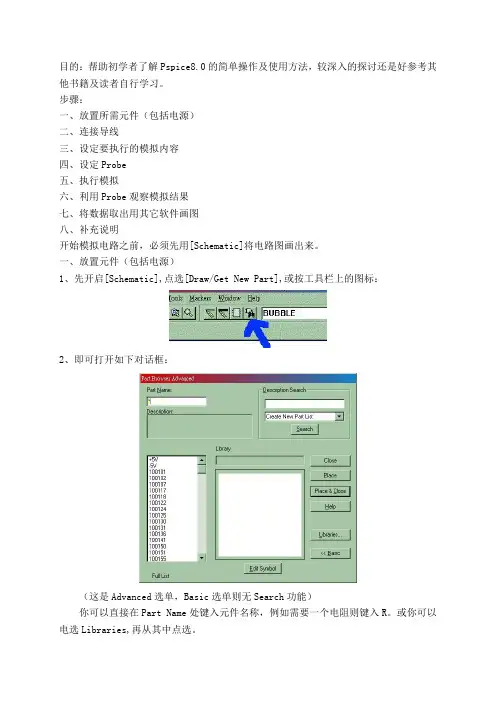
一、放置元件(包括电源)1、先开启[Schematic],点选[Draw/Get New Part],或按工具栏上的图标:2、即可打开如下对话框:(这是Advanced选单,Basic选单则无Search功能)你可以直接在Part Name处键入元件名称,例如需要一个电阻则键入R。
或你可以电选Libraries,再从其中点选。
你如果用的是 Pspice教学免费版,提供的Lebraries有限,但已能满足学习需求,不用担心。
常用的Librares内容如下:ANALOG.slb 常用的被动元件BREAKOUT.slb 可改变参数的基本元件SOURCE.slb 电源及信号源PORT.slb 接地及连接器ERAL.slb 常用的半导体元件(这是免费版专属元件库)3、确定元件后,按[Place]即可将元件拖放到电路图上,按一下鼠标左键,就可以将元件放在图面上,按右键则结束。
放完元件后,按的Close钮关闭对话框。
要改变元件的方向,可点选该元件,在执行[Edit/Rotate]菜单命令(快捷键Ctrl+R)或[Edit/Flip](快捷键Ctrl+F)。
4、要改变元件的参数(或称Attributes),可双击该元件,打开元件属性对话框。
如下图是一电阻,在1处点选VALUE,在2处键入需要的电阻值即可,然后按[Save Arrr],在按[OK]钮完成。
二、连接导线1、利用连线工具(Draw Wire)画导线。
2、点选画线工具后,即可看到一个铅笔状的指示。
将画笔移到起始端,按鼠标左键,开始引线,要转弯时可按以下鼠标左键,画笔移到终点后在按以下鼠标左键,完成接线。
pspice使用教程
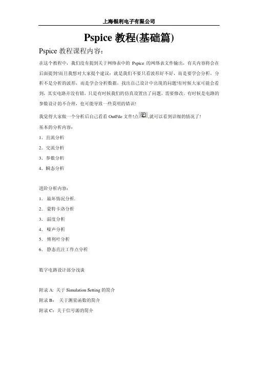
所用到的器件为: 器件 电源 电阻
(Fig.11)
模型 V1 R1
模型库 VAC/Source R/Analog_p
上海银利电子有限公司
电感
L1
电容
C1
地
0
现在我们来对 Simulation Setting 来进行设置!设置如下(Fig.12)
L/Analog_p C/ Analog_p
0/Source
上海银利电子有限公司
(Fig.13) 如果发现波形不是很好,我们可以修改一下,让显示的效果比较突出! 如何修改仿真波形参数呢?
点击 Edit Profile,就可以回到我们的仿真参数设置参数窗口!我们可以根据自己的需要来重 新来设置仿真参数!然后再来运行一下仿真结果。点 Run 命令或 ,再来一遍! *注意: 在 Fig.13 图中!我们测量显示的函数为 I(R1)! 以后文章中不会再提出一些关于调用哪些函数的信息!请读者从图纸上看! 在特定时候 我们会提示大家! 做出仿真波形,如何才能够测量出波形的具体的数据信息呢? 我们可以用 Toggle cursor 的工具来进行测量,点击小图标 ,我们可以看到后面的工具栏 由灰色锁定状态变为可用的状态!同时也会弹出一个小小的数据显示信息框。
将会显示出属性窗口,我们现在开始编辑属性窗口信息! 点击 New Row 将会弹出一个新的窗口,Add New Row 信息窗口! 我们按下图所示添写:
上海银利电子有限公司
点击 Apply 选项!ok! 这样我们就搞定了关于如何定义这个参数与 R1 之间的关系! 修改完成后的原理图:(Fig.14)
我觉得大家做一个分析后自己看看 OutFile 文件!点 基本的分析内容: 1.直流分析 2.交流分析 3.参数分析 4.瞬态分析
Pspice8.0快速入门手册

Pspice8.0快速入门手册目的:帮助初学者了解Pspice8.0的简单操作及使用方法,较深入的探讨还是好参考其他书籍及读者自行学习。
步骤:一、放置所需元件(包括电源)二、连接导线三、设定要执行的模拟内容四、设定Probe五、执行模拟六、利用Probe观察模拟结果七、将数据取出用其它软件画图八、补充说明开始模拟电路之前,必须先用[Schematic]将电路图画出来。
一、放置元件(包括电源)1、先开启[Schematic],点选[Draw/Get New Part],或按工具栏上的图标:2、即可打开如下对话框:(这是Advanced选单,Basic选单则无Search功能)你可以直接在Part Name处键入元件名称,例如需要一个电阻则键入R。
或你可以电选Libraries,再从其中点选。
你如果用的是 Pspice教学免费版,提供的Lebraries有限,但已能满足学习需求,不用担心。
常用的Librares内容如下:ANALOG.slb 常用的被动元件BREAKOUT.slb 可改变参数的基本元件SOURCE.slb 电源及信号源PORT.slb 接地及连接器ERAL.slb 常用的半导体元件(这是免费版专属元件库)3、确定元件后,按[Place]即可将元件拖放到电路图上,按一下鼠标左键,就可以将元件放在图面上,按右键则结束。
放完元件后,按的Close钮关闭对话框。
要改变元件的方向,可点选该元件,在执行[Edit/Rotate]菜单命令(快捷键Ctrl+R)或[Edit/Flip](快捷键Ctrl+F)。
4、要改变元件的参数(或称Attributes),可双击该元件,打开元件属性对话框。
如下图是一电阻,在1处点选VALUE,在2处键入需要的电阻值即可,然后按[Save Arrr],在按[OK]钮完成。
回到文件顶端二、连接导线1、利用连线工具(Draw Wire)画导线。
2、点选画线工具后,即可看到一个铅笔状的指示。
PSpice仿真软件使用指南说明书
April 2016© 2013Cadence Design Systems, Inc. All rights reserved.Portions © Apache Software Foundation, Sun Microsystems, Free Software Foundation, Inc., Regents of the University of California, Massachusetts Institute of T echnology, University of Florida. Used by permission. Printed in the United States of America.Cadence Design Systems, Inc. (Cadence), 2655 Seely Ave., San Jose, CA 95134, USA.Product PSpice contains technology licensed from, and copyrighted by: Apache Software Foundation, 1901 Munsey Drive Forest Hill, MD 21050, USA © 2000-2005,Apache Software Foundation. Sun Microsystems, 4150 Network Circle, Santa Clara, CA 95054 USA © 1994-2007, Sun Microsystems, Inc. Free Software Foundation, 59 Temple Place, Suite 330, Boston, MA 02111-1307 USA © 1989, 1991, Free Software Foundation, Inc. Regents of the University of California, Sun Microsystems, Inc., Scriptics Corporation, © 2001, Regents of the University of California. Daniel Stenberg, © 1996 - 2006, Daniel Stenberg. UMFPACK ©2005,TimothyA.Davis,UniversityofFlorida,(**************.edu).KenMartin,WillSchroeder,Bill Lorensen © 1993-2002, Ken Martin, Will Schroeder, Bill Lorensen. Massachusetts Institute of Technology, 77 Massachusetts Avenue, Cambridge, Massachusetts, USA © 2003, the Board of Trustees of Massachusetts Institute of Technology. All rights reserved.Trademarks: Trademarks and service marks of Cadence Design Systems, Inc. contained in this document are attributed to Cadence with the appropriate symbol. For queries regarding Cadence’s trademarks, contact the corporate legal department at the address shown above or call 800.862.4522.Open SystemC, Open SystemC Initiative, OSCI, SystemC, and SystemC Initiative are trademarks or registered trademarks of Open SystemC Initiative, Inc. in the United States and other countries and are used with permission.All other trademarks are the property of their respective holders.Restricted Permission: This publication is protected by copyright law and international treaties and contains trade secrets and proprietary information owned by Cadence. Unauthorized reproduction or distribution of this publication, or any portion of it, may result in civil and criminal penalties. Except as specified in this permission statement, this publication may not be copied, reproduced, modified, published, uploaded, posted, transmitted, or distributed in any way, without prior written permission from Cadence. Unless otherwise agreed to by Cadence in writing, this statement grants Cadence customers permission to print one (1) hard copy of this publication subject to the following conditions:1.The publication may be used only in accordance with a written agreement between Cadence and itscustomer.2.The publication may not be modified in any way.3.Any authorized copy of the publication or portion thereof must include all original copyright,trademark, and other proprietary notices and this permission statement.4.The information contained in this document cannot be used in the development of like products orsoftware, whether for internal or external use, and shall not be used for the benefit of any other party, whether or not for consideration.Disclaimer: Information in this publication is subject to change without notice and does not represent a commitment on the part of Cadence. Except as may be explicitly set forth in such agreement, Cadence does not make, and expressly disclaims, any representations or warranties as to the completeness, accuracy or usefulness of the information contained in this document. Cadence does not warrant that use of such information will not infringe any third party rights, nor does Cadence assume any liability for damages or costs of any kind that may result from use of such information.Restricted Rights: Use, duplication, or disclosure by the Government is subject to restrictions as set forth in FAR52.227-14 and DFAR252.227-7013 et seq. or its successor.ContentsBefore you begin. . . . . . . . . . . . . . . . . . . . . . . . . . . . . . . . . . . . . . . . . . . . . . . . . . 21 Welcome . . . . . . . . . . . . . . . . . . . . . . . . . . . . . . . . . . . . . . . . . . . . . . . . . . . . . . . . . . . . . 21 How to use this guide . . . . . . . . . . . . . . . . . . . . . . . . . . . . . . . . . . . . . . . . . . . . . . . . . . . 22 Symbols and conventions . . . . . . . . . . . . . . . . . . . . . . . . . . . . . . . . . . . . . . . . . . . . . . 22 Related documentation . . . . . . . . . . . . . . . . . . . . . . . . . . . . . . . . . . . . . . . . . . . . . . . 23 What this user’s guide covers . . . . . . . . . . . . . . . . . . . . . . . . . . . . . . . . . . . . . . . . . . . . . 26 PSpice overview . . . . . . . . . . . . . . . . . . . . . . . . . . . . . . . . . . . . . . . . . . . . . . . . . . . . 26 Add-on options . . . . . . . . . . . . . . . . . . . . . . . . . . . . . . . . . . . . . . . . . . . . . . . . . . . . . . . . . 27 PSpice Smoke Option . . . . . . . . . . . . . . . . . . . . . . . . . . . . . . . . . . . . . . . . . . . . . . . . 27 PSpice Advanced Optimizer Option . . . . . . . . . . . . . . . . . . . . . . . . . . . . . . . . . . . . . . 27 PSpice Advanced Analysis . . . . . . . . . . . . . . . . . . . . . . . . . . . . . . . . . . . . . . . . . . . . . 27 SLPS . . . . . . . . . . . . . . . . . . . . . . . . . . . . . . . . . . . . . . . . . . . . . . . . . . . . . . . . . . . . . 28 If you don’t have the standard PSpice A/D package . . . . . . . . . . . . . . . . . . . . . . . . . . . . 28 Comparison of the different versions of PSpice . . . . . . . . . . . . . . . . . . . . . . . . . . . . . 28 If you have PSpice Lite . . . . . . . . . . . . . . . . . . . . . . . . . . . . . . . . . . . . . . . . . . . . . . . . 31 Minimum hardware requirements for running PSpice: . . . . . . . . . . . . . . . . . . . . . . . . 32 PSpice Samples and T utorials . . . . . . . . . . . . . . . . . . . . . . . . . . . . . . . . . . . . . . . . . . . . . 32 Part one: Simulation primer . . . . . . . . . . . . . . . . . . . . . . . . . . . . . . . . . . . . . 33 1Things you need to know . . . . . . . . . . . . . . . . . . . . . . . . . . . . . . . . . . . . . . . . 35 Chapter overview . . . . . . . . . . . . . . . . . . . . . . . . . . . . . . . . . . . . . . . . . . . . . . . . . . . . . . . 35 What is PSpice? . . . . . . . . . . . . . . . . . . . . . . . . . . . . . . . . . . . . . . . . . . . . . . . . . . . . . . . 36 Analyses you can run with PSpice . . . . . . . . . . . . . . . . . . . . . . . . . . . . . . . . . . . . . . . . . . 40 Basic analyses . . . . . . . . . . . . . . . . . . . . . . . . . . . . . . . . . . . . . . . . . . . . . . . . . . . . . . 40 Advanced multi-run analyses . . . . . . . . . . . . . . . . . . . . . . . . . . . . . . . . . . . . . . . . . . . 43 Analyzing waveforms with PSpice . . . . . . . . . . . . . . . . . . . . . . . . . . . . . . . . . . . . . . . . . . 45 What is waveform analysis? . . . . . . . . . . . . . . . . . . . . . . . . . . . . . . . . . . . . . . . . . . . 45 Using PSpice with other programs . . . . . . . . . . . . . . . . . . . . . . . . . . . . . . . . . . . . . . . . . . 47 Using design entry tools to prepare for simulation . . . . . . . . . . . . . . . . . . . . . . . . . . 47What is the PSpice Stimulus Editor? . . . . . . . . . . . . . . . . . . . . . . . . . . . . . . . . . . . . . 48 What is the PSpice Model Editor? . . . . . . . . . . . . . . . . . . . . . . . . . . . . . . . . . . . . . . . 49 Files needed for simulation . . . . . . . . . . . . . . . . . . . . . . . . . . . . . . . . . . . . . . . . . . . . . . . 49 Files that design entry tool generates . . . . . . . . . . . . . . . . . . . . . . . . . . . . . . . . . . . . 50 Other files that you can configure for simulation . . . . . . . . . . . . . . . . . . . . . . . . . . . . 53 Files that PSpice generates . . . . . . . . . . . . . . . . . . . . . . . . . . . . . . . . . . . . . . . . . . . . . . . 55 Directory structure for analog projects in Capture . . . . . . . . . . . . . . . . . . . . . . . . . . . . . 58 How are files configured at the design level maintained in the directory structure for analog projects? . . . . . . . . . . . . . . . . . . . . . . . . . . . . . . . . . . . . . . . . . . . . . . . . . . . . . . . . . . . 59 How are files configured at the profile level maintained in the new directory structure for analog projects? . . . . . . . . . . . . . . . . . . . . . . . . . . . . . . . . . . . . . . . . . . . . . . . . . . . . . 61 What happens when I convert an analog project that uses a design from another project or from another location? . . . . . . . . . . . . . . . . . . . . . . . . . . . . . . . . . . . . . . . . . . . . . . 63 What should I do if the schematic for a converted analog project uses FILESTIM n parts from the SOURCE library? . . . . . . . . . . . . . . . . . . . . . . . . . . . . . . . . . . . . . . . . . . . . . 63 Design Entry HDL libraries . . . . . . . . . . . . . . . . . . . . . . . . . . . . . . . . . . . . . . . . . . . . . . . 64 Reference Libraries . . . . . . . . . . . . . . . . . . . . . . . . . . . . . . . . . . . . . . . . . . . . . . . . . . 66 Local libraries . . . . . . . . . . . . . . . . . . . . . . . . . . . . . . . . . . . . . . . . . . . . . . . . . . . . . . . 68 PSpice model libraries . . . . . . . . . . . . . . . . . . . . . . . . . . . . . . . . . . . . . . . . . . . . . . . . 69 The cds.lib file . . . . . . . . . . . . . . . . . . . . . . . . . . . . . . . . . . . . . . . . . . . . . . . . . . . . . . 69 Encrypting PSpice Models . . . . . . . . . . . . . . . . . . . . . . . . . . . . . . . . . . . . . . . . . . . . . . . 71 Using PSpiceEnc . . . . . . . . . . . . . . . . . . . . . . . . . . . . . . . . . . . . . . . . . . . . . . . . . . . . 72 Using Model Editor . . . . . . . . . . . . . . . . . . . . . . . . . . . . . . . . . . . . . . . . . . . . . . . . . . . 722Simulation examples . . . . . . . . . . . . . . . . . . . . . . . . . . . . . . . . . . . . . . . . . . . . . 75 Chapter overview . . . . . . . . . . . . . . . . . . . . . . . . . . . . . . . . . . . . . . . . . . . . . . . . . . . . . . . 75 Example circuit creation . . . . . . . . . . . . . . . . . . . . . . . . . . . . . . . . . . . . . . . . . . . . . . . . . . 76 Using Capture . . . . . . . . . . . . . . . . . . . . . . . . . . . . . . . . . . . . . . . . . . . . . . . . . . . . . . 76 Using Design Entry HDL . . . . . . . . . . . . . . . . . . . . . . . . . . . . . . . . . . . . . . . . . . . . . . 85 Using Design T emplates . . . . . . . . . . . . . . . . . . . . . . . . . . . . . . . . . . . . . . . . . . . . . . . 93 Finding out more about setting up your design . . . . . . . . . . . . . . . . . . . . . . . . . . . . . 95 Running PSpice . . . . . . . . . . . . . . . . . . . . . . . . . . . . . . . . . . . . . . . . . . . . . . . . . . . . . . . . 95 Performing a bias point analysis . . . . . . . . . . . . . . . . . . . . . . . . . . . . . . . . . . . . . . . . . 96 Using the simulation output file . . . . . . . . . . . . . . . . . . . . . . . . . . . . . . . . . . . . . . . . . 98 Finding out more about bias point calculations . . . . . . . . . . . . . . . . . . . . . . . . . . . . . 99DC sweep analysis . . . . . . . . . . . . . . . . . . . . . . . . . . . . . . . . . . . . . . . . . . . . . . . . . . . . . 99 Setting up and running a DC sweep analysis . . . . . . . . . . . . . . . . . . . . . . . . . . . . . . . 99 Displaying DC analysis results . . . . . . . . . . . . . . . . . . . . . . . . . . . . . . . . . . . . . . . . . 101 Finding out more about DC sweep analysis . . . . . . . . . . . . . . . . . . . . . . . . . . . . . . . 107 T ransient analysis . . . . . . . . . . . . . . . . . . . . . . . . . . . . . . . . . . . . . . . . . . . . . . . . . . . . . 108 Finding out more about transient analysis . . . . . . . . . . . . . . . . . . . . . . . . . . . . . . . . 115 AC sweep analysis . . . . . . . . . . . . . . . . . . . . . . . . . . . . . . . . . . . . . . . . . . . . . . . . . . . . . 116 Setting up and running an AC sweep analysis . . . . . . . . . . . . . . . . . . . . . . . . . . . . . 116 AC sweep analysis results . . . . . . . . . . . . . . . . . . . . . . . . . . . . . . . . . . . . . . . . . . . . 120 Finding out more about AC sweep and noise analysis . . . . . . . . . . . . . . . . . . . . . . . 122 Parametric analysis . . . . . . . . . . . . . . . . . . . . . . . . . . . . . . . . . . . . . . . . . . . . . . . . . . . . 123 Setting up and running the parametric analysis . . . . . . . . . . . . . . . . . . . . . . . . . . . . 126 Analyzing waveform families . . . . . . . . . . . . . . . . . . . . . . . . . . . . . . . . . . . . . . . . . . 130 Finding out more about parametric analysis . . . . . . . . . . . . . . . . . . . . . . . . . . . . . . 133 Performance analysis . . . . . . . . . . . . . . . . . . . . . . . . . . . . . . . . . . . . . . . . . . . . . . . . . . 134 Finding out more about performance analysis . . . . . . . . . . . . . . . . . . . . . . . . . . . . . 136Part two: Design entry . . . . . . . . . . . . . . . . . . . . . . . . . . . . . . . . . . . . . . . . . . 1383Preparing a design for simulation. . . . . . . . . . . . . . . . . . . . . . . . . . . . . . 139 Chapter overview . . . . . . . . . . . . . . . . . . . . . . . . . . . . . . . . . . . . . . . . . . . . . . . . . . . . . . 139 Checklist for simulation setup . . . . . . . . . . . . . . . . . . . . . . . . . . . . . . . . . . . . . . . . . . . . 140 T ypical simulation setup steps . . . . . . . . . . . . . . . . . . . . . . . . . . . . . . . . . . . . . . . . . 140 Advanced design entry and simulation setup steps . . . . . . . . . . . . . . . . . . . . . . . . . 141 When netlisting fails or the simulation does not start . . . . . . . . . . . . . . . . . . . . . . . . 142 Using parts that you can simulate . . . . . . . . . . . . . . . . . . . . . . . . . . . . . . . . . . . . . . . . . 143 Vendor-supplied parts . . . . . . . . . . . . . . . . . . . . . . . . . . . . . . . . . . . . . . . . . . . . . . . 144 Passive parts . . . . . . . . . . . . . . . . . . . . . . . . . . . . . . . . . . . . . . . . . . . . . . . . . . . . . . 152 Breakout parts . . . . . . . . . . . . . . . . . . . . . . . . . . . . . . . . . . . . . . . . . . . . . . . . . . . . . 153 Behavioral parts . . . . . . . . . . . . . . . . . . . . . . . . . . . . . . . . . . . . . . . . . . . . . . . . . . . . 154 Simulating asymmetric parts in PSpice . . . . . . . . . . . . . . . . . . . . . . . . . . . . . . . . . . 155 Simulating homogenous parts in PSpice . . . . . . . . . . . . . . . . . . . . . . . . . . . . . . . . . 156 Specifying values for part properties . . . . . . . . . . . . . . . . . . . . . . . . . . . . . . . . . . . . . . . 157 Using global parameters and expressions for values . . . . . . . . . . . . . . . . . . . . . . . . . . 158Global parameters . . . . . . . . . . . . . . . . . . . . . . . . . . . . . . . . . . . . . . . . . . . . . . . . . . 158 Expressions . . . . . . . . . . . . . . . . . . . . . . . . . . . . . . . . . . . . . . . . . . . . . . . . . . . . . . . 162 Defining power supplies . . . . . . . . . . . . . . . . . . . . . . . . . . . . . . . . . . . . . . . . . . . . . . . . . 170 For the analog portion of your circuit . . . . . . . . . . . . . . . . . . . . . . . . . . . . . . . . . . . . 170 For A/D interfaces in mixed-signal circuits . . . . . . . . . . . . . . . . . . . . . . . . . . . . . . . . 170 Defining stimuli . . . . . . . . . . . . . . . . . . . . . . . . . . . . . . . . . . . . . . . . . . . . . . . . . . . . . . . 172 Analog stimuli . . . . . . . . . . . . . . . . . . . . . . . . . . . . . . . . . . . . . . . . . . . . . . . . . . . . . . 172 Digital stimuli . . . . . . . . . . . . . . . . . . . . . . . . . . . . . . . . . . . . . . . . . . . . . . . . . . . . . . 176 Things to watch for . . . . . . . . . . . . . . . . . . . . . . . . . . . . . . . . . . . . . . . . . . . . . . . . . . . . . 178 Unmodeled parts . . . . . . . . . . . . . . . . . . . . . . . . . . . . . . . . . . . . . . . . . . . . . . . . . . . 178 Unconfigured model, stimulus, or include files . . . . . . . . . . . . . . . . . . . . . . . . . . . . . 182 Unmodeled pins . . . . . . . . . . . . . . . . . . . . . . . . . . . . . . . . . . . . . . . . . . . . . . . . . . . . 184 Missing ground . . . . . . . . . . . . . . . . . . . . . . . . . . . . . . . . . . . . . . . . . . . . . . . . . . . . . 184 Missing DC path to ground . . . . . . . . . . . . . . . . . . . . . . . . . . . . . . . . . . . . . . . . . . . . 1854Creating and editing models . . . . . . . . . . . . . . . . . . . . . . . . . . . . . . . . . . . 187 Chapter overview . . . . . . . . . . . . . . . . . . . . . . . . . . . . . . . . . . . . . . . . . . . . . . . . . . . . . . 187 What are models? . . . . . . . . . . . . . . . . . . . . . . . . . . . . . . . . . . . . . . . . . . . . . . . . . . . . . 189 How are models organized? . . . . . . . . . . . . . . . . . . . . . . . . . . . . . . . . . . . . . . . . . . . . . 190 Model libraries . . . . . . . . . . . . . . . . . . . . . . . . . . . . . . . . . . . . . . . . . . . . . . . . . . . . . 190 Model library configuration . . . . . . . . . . . . . . . . . . . . . . . . . . . . . . . . . . . . . . . . . . . . 191 Global vs. design vs. profile models and libraries . . . . . . . . . . . . . . . . . . . . . . . . . . 191 Nested model libraries . . . . . . . . . . . . . . . . . . . . . . . . . . . . . . . . . . . . . . . . . . . . . . . 192 PSpice-provided models . . . . . . . . . . . . . . . . . . . . . . . . . . . . . . . . . . . . . . . . . . . . . 193 Model library data . . . . . . . . . . . . . . . . . . . . . . . . . . . . . . . . . . . . . . . . . . . . . . . . . . . 193 Device characteristic curves-based models vs. Template-based models . . . . . . . . 195 T ools to create and edit models . . . . . . . . . . . . . . . . . . . . . . . . . . . . . . . . . . . . . . . . . . . 197 Ways to create and edit models . . . . . . . . . . . . . . . . . . . . . . . . . . . . . . . . . . . . . . . . . . . 198 Using the Model Editor . . . . . . . . . . . . . . . . . . . . . . . . . . . . . . . . . . . . . . . . . . . . . . . . . 200 Ways to use the Model Editor . . . . . . . . . . . . . . . . . . . . . . . . . . . . . . . . . . . . . . . . . . 201 Running the Model Editor alone . . . . . . . . . . . . . . . . . . . . . . . . . . . . . . . . . . . . . . . . . . 202 Starting the Model Editor . . . . . . . . . . . . . . . . . . . . . . . . . . . . . . . . . . . . . . . . . . . . . 203 Creating models using the Model Editor . . . . . . . . . . . . . . . . . . . . . . . . . . . . . . . . . . . . 203 Creating models based on device characteristic curves . . . . . . . . . . . . . . . . . . . . . 203Creating models based on PSpice templates . . . . . . . . . . . . . . . . . . . . . . . . . . . . . 209 Importing an existing model . . . . . . . . . . . . . . . . . . . . . . . . . . . . . . . . . . . . . . . . . . . 212 Enabling and disabling automatic part creation . . . . . . . . . . . . . . . . . . . . . . . . . . . . 213 Running the Model Editor from the schematic editor . . . . . . . . . . . . . . . . . . . . . . . . 215 Model creation examples . . . . . . . . . . . . . . . . . . . . . . . . . . . . . . . . . . . . . . . . . . . . . . . . 218 Example: Creating a PSpice model based on device characteristic curves . . . . . . . 219 Example: Creating template-based PSpice model . . . . . . . . . . . . . . . . . . . . . . . . . . 228 Editing model text . . . . . . . . . . . . . . . . . . . . . . . . . . . . . . . . . . . . . . . . . . . . . . . . . . . . . 234 Example: editing a Q2N2222 instance model . . . . . . . . . . . . . . . . . . . . . . . . . . . . . 236 Using the Create Subcircuit Format Netlist command (Capture only) . . . . . . . . . . . . . . 237 Changing the model reference to an existing model definition . . . . . . . . . . . . . . . . . . . 239 Reusing instance models . . . . . . . . . . . . . . . . . . . . . . . . . . . . . . . . . . . . . . . . . . . . . . . . 240 Reusing instance models in the same schematic . . . . . . . . . . . . . . . . . . . . . . . . . . 241 Making instance models available to all designs . . . . . . . . . . . . . . . . . . . . . . . . . . . 241 Configuring model libraries . . . . . . . . . . . . . . . . . . . . . . . . . . . . . . . . . . . . . . . . . . . . . . 243 The Configuration Files tab . . . . . . . . . . . . . . . . . . . . . . . . . . . . . . . . . . . . . . . . . . . 244 How PSpice uses model libraries . . . . . . . . . . . . . . . . . . . . . . . . . . . . . . . . . . . . . . . 245 Adding model libraries to the configuration . . . . . . . . . . . . . . . . . . . . . . . . . . . . . . . 248 Changing the model library scope from profile to design, profile to global, design to global and vice versa . . . . . . . . . . . . . . . . . . . . . . . . . . . . . . . . . . . . . . . . . . . . . . . . . . . . . 249 Changing model library search order . . . . . . . . . . . . . . . . . . . . . . . . . . . . . . . . . . . . 250 Changing the library search path . . . . . . . . . . . . . . . . . . . . . . . . . . . . . . . . . . . . . . . 252 Handling smoke information using the Model Editor . . . . . . . . . . . . . . . . . . . . . . . . . . . 254 Adding smoke information to PSpice models . . . . . . . . . . . . . . . . . . . . . . . . . . . . . . 254 Creating template-based PSpice models with smoke information . . . . . . . . . . . . . . 256 Using the Model Editor to edit smoke information . . . . . . . . . . . . . . . . . . . . . . . . . . 256 Examples: Smoke . . . . . . . . . . . . . . . . . . . . . . . . . . . . . . . . . . . . . . . . . . . . . . . . . . . . . 257 Adding smoke information to the D1 diode model . . . . . . . . . . . . . . . . . . . . . . . . . . 257 Adding smoke information to the OPA_LOCAL operational amplifier model . . . . . . 259 Smoke parameters . . . . . . . . . . . . . . . . . . . . . . . . . . . . . . . . . . . . . . . . . . . . . . . . . . . . . 260 Diode . . . . . . . . . . . . . . . . . . . . . . . . . . . . . . . . . . . . . . . . . . . . . . . . . . . . . . . . . . . . 261 Bipolar Junction Transistors . . . . . . . . . . . . . . . . . . . . . . . . . . . . . . . . . . . . . . . . . . . 262 Magnetic Core . . . . . . . . . . . . . . . . . . . . . . . . . . . . . . . . . . . . . . . . . . . . . . . . . . . . . 264 Ins Gate Bipolar T ransistor (IGBT) . . . . . . . . . . . . . . . . . . . . . . . . . . . . . . . . . . . . . . 264 Junction FET . . . . . . . . . . . . . . . . . . . . . . . . . . . . . . . . . . . . . . . . . . . . . . . . . . . . . . 266 Operational Amplifier . . . . . . . . . . . . . . . . . . . . . . . . . . . . . . . . . . . . . . . . . . . . . . . . 268MOSFET . . . . . . . . . . . . . . . . . . . . . . . . . . . . . . . . . . . . . . . . . . . . . . . . . . . . . . . . . 270 Voltage Regulator . . . . . . . . . . . . . . . . . . . . . . . . . . . . . . . . . . . . . . . . . . . . . . . . . . . 271 Darlington T ransistor . . . . . . . . . . . . . . . . . . . . . . . . . . . . . . . . . . . . . . . . . . . . . . . . 2735Creating parts for models. . . . . . . . . . . . . . . . . . . . . . . . . . . . . . . . . . . . . . . 275 Chapter overview . . . . . . . . . . . . . . . . . . . . . . . . . . . . . . . . . . . . . . . . . . . . . . . . . . . . . . 275 What’s different about parts used for simulation? . . . . . . . . . . . . . . . . . . . . . . . . . . . . . 276 Ways to create parts for models . . . . . . . . . . . . . . . . . . . . . . . . . . . . . . . . . . . . . . . . . . 277 Preparing your models for part creation . . . . . . . . . . . . . . . . . . . . . . . . . . . . . . . . . . . . 279 Starting the Model Editor . . . . . . . . . . . . . . . . . . . . . . . . . . . . . . . . . . . . . . . . . . . . . . . . 280 Using the Model Editor to create parts . . . . . . . . . . . . . . . . . . . . . . . . . . . . . . . . . . . . . 281 Batch mode of part creation . . . . . . . . . . . . . . . . . . . . . . . . . . . . . . . . . . . . . . . . . . . 281 Interactive mode of part creation . . . . . . . . . . . . . . . . . . . . . . . . . . . . . . . . . . . . . . . 281 Creating Design Entry T ool parts for all models in a library . . . . . . . . . . . . . . . . . . . . . . 282 Using batch mode . . . . . . . . . . . . . . . . . . . . . . . . . . . . . . . . . . . . . . . . . . . . . . . . . . 282 Using interactive mode . . . . . . . . . . . . . . . . . . . . . . . . . . . . . . . . . . . . . . . . . . . . . . . 284 Setting up automatic part creation . . . . . . . . . . . . . . . . . . . . . . . . . . . . . . . . . . . . . . . . . 289 Example . . . . . . . . . . . . . . . . . . . . . . . . . . . . . . . . . . . . . . . . . . . . . . . . . . . . . . . . . . . . . 290 Creating parts in the batch mode . . . . . . . . . . . . . . . . . . . . . . . . . . . . . . . . . . . . . . . 290 Creating parts using interactive mode . . . . . . . . . . . . . . . . . . . . . . . . . . . . . . . . . . . 296 Basing new parts on a custom set of parts . . . . . . . . . . . . . . . . . . . . . . . . . . . . . . . . . . 300 Editing part graphics (Capture only) . . . . . . . . . . . . . . . . . . . . . . . . . . . . . . . . . . . . . . . 303 How Capture places parts . . . . . . . . . . . . . . . . . . . . . . . . . . . . . . . . . . . . . . . . . . . . 303 Defining grid spacing . . . . . . . . . . . . . . . . . . . . . . . . . . . . . . . . . . . . . . . . . . . . . . . . 304 Attaching models to parts . . . . . . . . . . . . . . . . . . . . . . . . . . . . . . . . . . . . . . . . . . . . . . . 306 MODEL . . . . . . . . . . . . . . . . . . . . . . . . . . . . . . . . . . . . . . . . . . . . . . . . . . . . . . . . . . . 306 Defining part properties needed for simulation . . . . . . . . . . . . . . . . . . . . . . . . . . . . . . . 308 PSPICETEMPLATE . . . . . . . . . . . . . . . . . . . . . . . . . . . . . . . . . . . . . . . . . . . . . . . . . 310 IO_LEVEL . . . . . . . . . . . . . . . . . . . . . . . . . . . . . . . . . . . . . . . . . . . . . . . . . . . . . . . . 319 MNTYMXDL Y . . . . . . . . . . . . . . . . . . . . . . . . . . . . . . . . . . . . . . . . . . . . . . . . . . . . . . 320 PSPICEDEFAULTNET . . . . . . . . . . . . . . . . . . . . . . . . . . . . . . . . . . . . . . . . . . . . . . . 3216Analog behavioral modeling. . . . . . . . . . . . . . . . . . . . . . . . . . . . . . . . . . . . 323 Chapter overview . . . . . . . . . . . . . . . . . . . . . . . . . . . . . . . . . . . . . . . . . . . . . . . . . . . . . . 323 Overview of analog behavioral modeling . . . . . . . . . . . . . . . . . . . . . . . . . . . . . . . . . . . . 324 The ABM part library file . . . . . . . . . . . . . . . . . . . . . . . . . . . . . . . . . . . . . . . . . . . . . . . . 325 Placing and specifying ABM parts . . . . . . . . . . . . . . . . . . . . . . . . . . . . . . . . . . . . . . . . . 326 Net names and device names in ABM expressions . . . . . . . . . . . . . . . . . . . . . . . . . 326 Forcing the use of a global definition . . . . . . . . . . . . . . . . . . . . . . . . . . . . . . . . . . . . 327 ABM part templates . . . . . . . . . . . . . . . . . . . . . . . . . . . . . . . . . . . . . . . . . . . . . . . . . . . . 328 Control system parts . . . . . . . . . . . . . . . . . . . . . . . . . . . . . . . . . . . . . . . . . . . . . . . . . . . 329 Basic components . . . . . . . . . . . . . . . . . . . . . . . . . . . . . . . . . . . . . . . . . . . . . . . . . . 332 Limiters . . . . . . . . . . . . . . . . . . . . . . . . . . . . . . . . . . . . . . . . . . . . . . . . . . . . . . . . . . . 333 Chebyshev filters . . . . . . . . . . . . . . . . . . . . . . . . . . . . . . . . . . . . . . . . . . . . . . . . . . . 334 Integrator and differentiator . . . . . . . . . . . . . . . . . . . . . . . . . . . . . . . . . . . . . . . . . . . 338 T able look-up parts . . . . . . . . . . . . . . . . . . . . . . . . . . . . . . . . . . . . . . . . . . . . . . . . . . 339 Laplace transform part . . . . . . . . . . . . . . . . . . . . . . . . . . . . . . . . . . . . . . . . . . . . . . . 344 Math functions . . . . . . . . . . . . . . . . . . . . . . . . . . . . . . . . . . . . . . . . . . . . . . . . . . . . . 348 ABM expression parts . . . . . . . . . . . . . . . . . . . . . . . . . . . . . . . . . . . . . . . . . . . . . . . 349 An instantaneous device example: modeling a triode . . . . . . . . . . . . . . . . . . . . . . . 353 PSpice-equivalent parts . . . . . . . . . . . . . . . . . . . . . . . . . . . . . . . . . . . . . . . . . . . . . . . . . 356 Implementation of PSpice-equivalent parts . . . . . . . . . . . . . . . . . . . . . . . . . . . . . . . 357 Modeling mathematical or instantaneous relationships . . . . . . . . . . . . . . . . . . . . . . 358 Lookup tables (ET ABLE and GT ABLE) . . . . . . . . . . . . . . . . . . . . . . . . . . . . . . . . . . . 362 Frequency-domain device models . . . . . . . . . . . . . . . . . . . . . . . . . . . . . . . . . . . . . . 364 Laplace transforms (LAPLACE) . . . . . . . . . . . . . . . . . . . . . . . . . . . . . . . . . . . . . . . . 364 Frequency response tables (EFREQ and GFREQ) . . . . . . . . . . . . . . . . . . . . . . . . . 366 Cautions and recommendations for simulation and analysis . . . . . . . . . . . . . . . . . . . . . 369 Instantaneous device modeling . . . . . . . . . . . . . . . . . . . . . . . . . . . . . . . . . . . . . . . . 369 Frequency-domain parts . . . . . . . . . . . . . . . . . . . . . . . . . . . . . . . . . . . . . . . . . . . . . 370 Laplace transforms . . . . . . . . . . . . . . . . . . . . . . . . . . . . . . . . . . . . . . . . . . . . . . . . . . 370 T rading off computer resources for accuracy . . . . . . . . . . . . . . . . . . . . . . . . . . . . . . 374 Basic controlled sources . . . . . . . . . . . . . . . . . . . . . . . . . . . . . . . . . . . . . . . . . . . . . . . . 375 Creating custom ABM parts . . . . . . . . . . . . . . . . . . . . . . . . . . . . . . . . . . . . . . . . . . . 375。
第三次课程 PSpice快速入门1

第三次课程PSpice快速入门第一节PSpice开发环境本节通过一个简单的实例,逐步介绍PSpice的开发环境和使用方法一、启动Capture CIS点击开始->程序->Orcad Family Release 9.2->Capture CIS,启动仿真界面。
二、建立新工程点击菜单命令File/New/Project,图1或直接用工具栏上的快捷按钮。
弹出图3所示的对话框。
图2三、设置新工程文件的名称、路径以及所使用的模板图3图3中各项的含义如下:Name:工程文件名,可键入新建的设计项目名称。
Analog or Mixed A/D Project:所创建的工程可以进行模拟量仿真或模数混合仿真,仿真通过后也可以进行印制电路板的自动和手动布局布线。
本课程之介绍所绘制的电路图如何进行PSpice电路模拟,因此应选此项。
PC Board Wizard:所创建的工程可以直接进行印制电路板的布局布线,也可以选择相关选项进行模数混合仿真。
Schematic:所创建的工程只能设计原理图。
Location:选择新建工程文件的存放路径。
必须是已有的路径,此处无法自己创建新路径。
设置好后,单击OK按钮,出现图4所示界面,其中各项的含义如下:图4Create based upon an existing project:所创建的工程是基于已有的工程,这样选择已有工程后,新建工程可以再原有基础上进行修改。
Create a blank project:创建一个空白工程,相当于要在一张空白图纸上画图。
图5创建的空白工程包括三个窗口“SCHEMATIC1:PAGE1”窗口显示了一张空白的图纸,可以再图纸上绘制自己的电路图。
若没有工具栏,可单击“SCHEMATIC1:PAGE1”窗口,使其成为活动窗口,就会出现工具栏。
左下方“Session Log”窗口显示软件执行任务中的有关信息,在仿真中出现的错误也在此窗口显示。
PSpice使用教程

用于分析电路的频率响应和交流性能参数。
模拟分析类型
03
参数扫描分析可以应用于直流分析、交流分析和瞬态分析等模拟类型。
01
参数扫描分析是一种用于研究电路性能对电路元件参数变化的敏感性的方法。
02
通过在一定范围内扫描参数值,可以观察电路性能的变化,从而优化电路设计。
参数扫描分析
1
2
3
噪声分析是一种用于研究电路中噪声源及其对电路性能影响的模拟方法。
PSPICE常见问题与解决方案
A
B
C
D
如何解决仿真错误
错误信息查看
首先需要仔细查看仿真错误信息,了解错误类型和原因。
参数设置检查
检查仿真参数设置是否合理,如仿真时间、步长等。
电路图检查
检查电路图的连接是否正确,元件值是否设置正确,以及元件的封装形式是否符合要求。
软件版本兼容性
确保使用的PSPICE软件版本与电路设计兼容。
在PSPICE界面右上角点击“关闭”按钮,或者选择“文件”菜单中的“退出”选项来退出PSPICE。
启动与退出PSPICE
包含文件、编辑、查看、项目等常用命令。
菜单栏
PSPICE界面介绍
提供常用命令的快捷方式。
工具栏
用于绘制和编辑电路图。
电路图编辑区
显示当前选中元件或电路的属性。
属性窗口
包含各种元件供选择。
通过噪声分析,可以确定电路中噪声的主要来源,并优化电路设计以减小噪声影响。
噪声分析可以应用于交流分析和瞬态分析等模拟类型。
噪声分析
温度分析
01
温度分析是一种用于研究电路性能随温度变化的模拟方法。
02
通过温度分析,可以了解电路在不同温度下的性能表现,并优化电路设计以适应不同的工作温度范围。
Pspice使用指南
图 16-7 分析类型对话框
2. 点选你想要模拟的项目,然后进入个别设定视窗。常用的模拟内容有:
AC Sweep:交流扫描分析(包括躁声分析),要找频率响应用这项。 DC Sweep:直流扫描分析,一般的 I-V 特性用这项。 Bias Point Detail:直流工作点分析即可节点的偏压分析,通常一定选,是确省
可以做扫描的不是只有直流电压或交流电压,还有所列的其它参数, 图右必须键入电 源名称或全局参数名,扫描范围及间隔。假如要扫描的参数不只一个,则可使用 Nested Sweep 设定第二个扫描。
3. 进入 DC Sweep 设置窗口后,选 Global Parameter(全局参数)和 Linear(线性扫 描),在 Name 文本框后第一格内写入全局参数名 var,将 Start Value(扫描初长) 设为 1,End Value(扫描终值)设为 1k,Increment(扫描步长)设为 10。单击[OK] 结束操作。如图 16-8。
步骤:1. 绘制电路原理图(所要绘制图如 16-12 所示)
图 16-12 电路原理图
2024版《PSpice使用教程》课件
《PSpice使用教程》课件•引言•PSpice基础操作•电路元件与模型库•仿真设置与运行分析目•高级功能应用•故障排查与问题解决录引言它能够对电路进行直流分析、交流分析、瞬态分析等,并输出相应的电压、电流等波形图。
PSpice 广泛应用于电子工程、通信工程、自动化控制等领域。
PSpice是一款电子电路仿真软件,全称为Personal Simulation Program with Integrated Circuit Emphasis。
PSpice简介模拟电路设计和分析数字电路设计和验证混合信号电路仿真电源电路设计和优化PSpice应用领域本课件旨在帮助学习者掌握PSpice软件的使用方法,提高电子电路设计和分析能力。
课件结构本课件包括引言、基础知识、电路仿真实践、高级应用和结论等部分,其中引言部分介绍PSpice软件的基本概念、应用领域和课件目的;基础知识部分介绍电路仿真所需的基本理论和PSpice软件的基本操作;电路仿真实践部分通过实例演示PSpice软件的使用方法;高级应用部分介绍PSpice 软件在复杂电路设计中的应用;结论部分总结本课件的主要内容和学习成果。
课件目的课件目的和结构VSPSpice基础操作软件安装与启动系统要求安装步骤启动方法属性栏显示选中对象的属性和参数设置等。
显示当前打开的项目文件和电路图等。
工具栏提供常用工具的快捷按钮,如画笔、选择、移动、旋转等。
主界面组成包括菜单栏、工具栏、项目栏、菜单栏提供文件、编辑、视图、插入、模拟、工具和帮助等菜单选项。
界面布局及功能介绍菜单栏和工具栏使用菜单栏操作01工具栏操作02自定义工具栏03通过菜单栏或工具栏中的新建选项来创建一个新的PSpice 项目。
新建项目保存项目另存为功能最近打开项目通过菜单栏或工具栏中的保存选项来保存当前项目文件和电路图等。
用户可以选择将当前项目另存为其他格式或版本的文件。
PSpice 软件会自动记录最近打开过的项目文件,方便用户快速打开。
PSPICE入门_
Pspice9.2入门一、建立工程文件新建一个文件夹(名称为英文或数字组成)用于存放PSPICE文件,例如:F:/PSPICE/xin/xin1。
进入Capture画面中,按" File/NEW/Project "命令,产生(NEW Project)对话框,如下图。
在"名称"栏中,输入工程名(英文)。
在Location栏中,输入本项目要储存的磁盘文件夹路径。
在Create a New Project Using栏内选择Analog or Mixed-Signal Circuit Wizar选项(如果我们只是要绘制一张单纯的电路图,不需要在作任何进一步的处理,可以选Schematic)单击OK按钮,调出选择Create a blank project,建立一个空白的工程文件。
二、编辑原理图1.放置所需元件。
用鼠标单击Place/part,出现以下对话框:单击Add Library,选择添加库文件路径C:\Program Files\Orcad\Capture\Library\PSpice添加编缉原理图需要的库文件,例如Analog.olb,Source.olb,zetex.olb库文件,添加后界面如下:添加好库文件后即可从相应的库文件中选择元件编辑原理图,也可从编辑界面右侧工具栏中拖放元件。
•基本元器件库:1)商品化的元器件符号库:大都是不同型号的半导体器件和集成电路。
其库文件名称分为两类:①已元器件的类型为文件名.有:以74开头的各种TTL74系列的数字电路;CD4000库文件中的CMOS4000系列电路;BIPOLAR库文件中的各种型号双极晶体管(三极管);OPAMP库文件中的各种运算放大器等。
②在库文件名中包含公司名称。
有:SIEMEN库文件中的西门子公司生产的半导体器件;MOTOR开头的库文件中是摩托罗拉公司生产的器件等。
2)常用非商品化元器件符号ANALOGY库:模拟电路中各种无源器件,如电阻、电容、电感等。
PSpice使用入门
类似,添加输入阻抗坐标系,如图20。
图20
输出阻抗分析:先修改原理图,短接输入电源,将RL改为Vw。如图21。
图21
输出阻抗的表达式为V(Vw:+)/I(Vw);结果如图22
图22
===end===
By yf.x
11/3/2010
图15
3)交流分析:在Trace表达式栏输入DB(V(VO)/V(VI)),确定。分析结果如图16
图16
4)显示游标和添加标签:Trace / Cursor / display或单击 ;结果如图17
图17
添加标签,Plot / Label / Mark或 ,结果如图18。
图18
添加坐标系,在表达式栏输入Vp(VO)-Vp(VI),如图19。
图10
2)单击 /输入Tran /设置时域分析的参数如图11。
图11
3)类似设置AC Sweep,如图12所成网表文件,PSpice / Create Netlist;若此步报错,根据log查错。
6
1)直流分析:右击左侧的SHCEMATIC1-Bias / Make Active,然后选择PSpice / Run或单击 。分析结果如图13。
图9
2)需要注意的地方:双击Vs的元件符号,在弹出窗口将AC项设为5mv,单击apply;选择三极管符号,Edit / PSpice Model,将Bf改为50,保存。
4
1)Pspice / New simulation profile /在name栏输入Bias / Create;如图10所示,选择分析类型、输出文件选项,然后确定。
图13
2)瞬态分析:右击SCHEMATIC1-Tran / Make Active / Run ,添加trace,Trace / Add Trace或单击 。选择V(VO)结果如图14。