CS压力开关
美国CCS压力开关
1.通用型差压开关 604D 674D
2.通用加强防爆型差压开关 646DZE
3.紧凑加强防爆型差压开关 6900DZE
4.通用加强防爆型差压开关 673DE
5.用防爆型差压开关 674DE
6.经济实用型微差压开关 1823
3.紧凑型温度开关 6900T 6900TU
4.紧凑防爆型温度开关 6900TE 6900TUE。美国CCS压力开关 压力开关 CCS压力开关
福州法拉第机电设备有限公司,联系人:许慧玲,电话:0591-87407126-8005,手机:18965047741,传真:0591-87143500
【CCS产品介绍】美国CCS压力开关 压力开关 CCS压力开关
CCS开关
一、 压力开关
1.通用型压力开关 604G 604P
2.通用加强型压力开关 604GZ 604GZ-7011
3.通用防爆型压力开关 646GZ 646PE
4.通用加强防爆型压力开关 646GZE 646GZE-7011 6401GZE
5.紧凑型及紧凑加强型压力开关 6900G 6901G 6900GZ 6901GZ 6900P 6901P
美国CCS压力开关 压力开关 CCS压力开关
美国CCS公司(Custom Control Sensors International)是美国最大的专业压力,温度开关的制造厂,该厂已有超过50年的历史,CCS压力开关以优异的性能,良好的服务而载誉全球。压力开关在设计上采用专利的双弹簧膜片结构(DUAL-SNAP),该膜片材质特殊,性能稳定,开关动作果断,无任何中间态,克服了老式压力保护元件如压力继电器,电接点压力计的固有缺点,从而保证了元件的高精度与高可靠性。该产品动作值准确,重复性高,微压区响应好,无飘移,耐冲击,防振动,抗抖动,基本上不受温度等因素的影响。CCS公司产品性能稳定可靠,并获得ISO9002认证。CCS压力开关系列齐全,有高、中、低、微压力动作范围,亦有通用型、加强型、紧凑型、微型等不同型式以适合不同用途之选择,CCS压力、温度开关已在石化、电力、机械等各个工业领域得到广泛的应用。
海卓公司 CS-110 系列自动切换系统操作维护手册说明书

CS-110CS-110 Rev. 4/22/15这份海卓公司文件以英文版Instruction pages(CS-110)为准。
本翻译版本仅是为用户提供方便所有海卓公司的产品说明书都能在海卓公司的网站www.instruments.com找到翻译免责声明操作维护手册自 动 切 换 系 统104、主屏幕布局......... (3)I. (3)II. (5)III. (7)IV............................................................................................................................................................................................................ 4 .. (6)............................................................................ 8 .. (9)海卓公司CS-110系列自动切换系统目录安全信息概述1、内容2、一般规格3、功能概述安装说明1、电气连接2、概述1、按键操作2、LED显示说明3、基本操作4、Modbus通讯操作说明维护图示1、典型的系统安装图2、CS-110内部接线图3、CS-110显示屏流程图显示屏将会显示日期、时间、每组氯瓶的工作时间(电动球阀的开启时间)及(可选的)将显示系统的操作情况。
2个4-20mA输入通道可接收电子秤的信号,此功能是可选功能。
控制器接收两个压力开关信号,并提供控制信号对电动球阀进行操作。
LED和LCD指示灯功能介绍:外形尺寸:板和电源的任何部分。
电气:电路板和电路线都可能引起电击或电路,在确认电源已经断开之前,请不要触摸电路总述:在操作此设备之前,确保遵循所有的安全警示。
SS-2不同压力开关操作手册说明书
“SS-2 DIFFERENTIAL PRESSURE SWITCH OPERATION MANUAL OMP# 4202XDX000The pressure switch “BLOCK AND BLEED” action is the same when the instrument pressure is connected to the “LO IN” port and “HI IN” port is left unused. For this mode of operation, the switch acts as a normally closed valve and is called a low switch. When normal differential pressure is acting on the piston, the center O-ring on the spool is between the “HI IN” port and the “OUT” port thus preventing the instrument pressure from passing to the “HI PORT” of the switch body, but allowing it to flow from the “LO IN” port to the “OUT” port of the switch body. When the differential pressure decreases to an abnormal level, the spring force shifts to the spool and the middle o-ring on the spool becomes positioned between the “LO IN” port and “OUT” port. Pressure at the “LO IN” port is “BLOCKED” from entering the “OUT” port and pressure at the “OUT” port “BLEEDS” to atmosphere from the “HI IN” port. The Ruelco “SS-2” pneumaticdifferential pressure switch is a threeway block and bleed valve that isoperated by pressure acting on a pistonopposing an adjustable spring force. Itfunctions as either a normally closed ornormally open valve depending onthrough which the two ports theinstrument pressure is supplied. Theseports are marked as “HI IN” or “LO IN”on the switch body. The output port,marked “OUT” on the switch body, isthe same for either mode of operation.The difference between the pressuresacting on the upstream and downstreamsensing ports is the differential pressurewhich causes the valve to operate.When the instrument supply pressure isconnected to the “HI IN” port, the switchoperates as a normally open valve and iscalled a high switch. If the differentialpressure acting on the piston is at normallevels, it is insufficient to overcome thespring force. The middle o-ring on thespool is positioned between the “LO IN”and the “OUT” port, thus preventing theinstrument pressure from passing to the“LO IN” port of the switch body, butallowing it to pass from the “HI IN” portto the “OUT” port. When the differentialpressure acting on the piston becomeslarge enough to overcome the springforce, the spool shifts and the center o-ring moves between the “HI IN” portand the “OUT” port. Instrument pressure at the “OUT” port and downstream “BLEEDS” to atmosphere thru the “LO IN” port while supply pressure at the “HI IN” port is blocked from entering the “OUT” port.Changing the differential pressure value when the switch is used as either a high or low is done by altering the force of the spring. Changing the spring force is accomplished by turning the spring cap to increase or decrease the spring compression.2.0 INSTALLATION: 2. Small pliers.3. High quality silicone base lubricant.The “SS-2” differential can be panel mounted (with optional panel mount nut) or supported by piping from the sense port in either vertical or horizontal positions. If the switch is mounted horizontally, it is recommended that the small vent hole in the side of the switch body be oriented in a downward position. This will prevent any debris from accumulating in the spring cavity or above the sense piston. 4. An appropriate safety solvent. 3.1 PARTIAL DISASSEMBLY A) Spring Removal3.1.1)If the switch is installed in an operating instrument system, it is not necessary to remove any instrument supply or sense pressure. If the unit is a high switch, it will trip when changing the spring; if it is a low switch, then it will not. So precautions should be taken to avoid any unwanted reactions in the instrumentation system.Proper pipe thread sealant should be used on any pipe fittings threaded into the pressure switch ports. If stainless steel fittings are used, a sealant that will prevent galling is required. The supply gas flowing through the switch body should be filtered and free of large particles. If compressed air is used, it does not have to be lubricated. If natural gas is used as the instrument pressure, then it should contain as little condensate or crude oil as possible. This will extend the life of the seals. When the switch is mounted using the 1/4” NPT base connection and the instrument pressure ports are not in the desired position after the base connection is adequately tightened, DO NOT loosen the body from the base to re-position the ports. Instead, remove the switch and re-make the 1/4” NPT connection.3.1.2) To obtain access to the spring(Item 2), rotate the lock ring (Item 4) clockwise to loosen it from the spring cap (Item 1).3.1.3) Rotate the spring cap (Item 1)counterclockwise until it is disengaged from the switch body (Item 8).3.1.4) Remove the spring from itscavity in the switch body.3.0 DISASSEMBLY (See Spec Sheet)3.1.5) Follow the procedures in repairand assembly section (Steps 4.1.4 and 4.14) of this manual to re-install the spring.Tools and materials required for proper disassembly, repair and assembly are as follows: 1. 7/8” and 1” open end wrenchesor two crescent wrenches of adequate size.B)Piston Removal3.1.6)If the switch is panel mounted, itis not necessary to remove itfrom the panel. It will benecessary to disconnect anypiping or tubing from the basethat would prevent the base frombeing removed. When the switchis supported by the ¼” NPTconnection on its base (Item 12),disconnect any piping or tubingfrom the switch body that wouldprevent its removal from theswitch base. CAUTION: Be surethat all instrument or sensepressures are completely bled tozero before disconnecting anypiping or tubing.3.1.7)Use the appropriate wrenches tohold and loosen the base from theswitch body. Unthread the basecompletely from the switch body. 3.1.8)Unthread the lower housing(Item 18) from the baseassembly. Use appropriatewrench to loosen the hex nutItem 19) from the shaft-pistonassembly.3.1.9)Remove the installed cup seal(Item 16) from the piston (Item17).3.1.10)Procedure for re-installing thepiston cup seal and the shaft sealis in the repair and assemblyprocedure of this manual.3.2FULL DISASSEMBLYNOTE: Use the following instructions to completely disassemble the pilot for repair and cleaning. CAUTION: Be sure that all instrument or sense pressures are completely bled to zero before disconnecting any piping or tubing.3.2.1)Follow the procedures statedunder partial disassembly toremove the spring and piston.3.2.2)Remove the spool (Item 8) fromthe switch body. If it isnecessary, use the small pliersand grip the large end of thespool.3.2.3)The seals on the spool, (Item 8)may now be replaced as perinstructions given in the repairand assembly section of thismanual.4.0REPAIR AND ASSEMBLY(See product data sheet forreplacement part numbers).4.1)Remove the seals from the spooland piston.4.2)Clean all parts using anappropriate safety solvent.4.3)Inspect the spool for any majordamage such as burrs or nicks onits outside diameter. Also inspectit for straightness. Replace thespool (Item 10) if damaged.4.4)Examine the polished bores ofthe switch body (Item 8) andbase (Item 12) for gouges andrough surfaces. Be sure that allheavy dirt deposits have beenremoved. Replace any damagedpieces.4.13) Install the lock ring onto theswitch body and place the spring plate into the body cavity. NOTE : If the switch is panel mounted, install it into the panel and secure with a panel mounting ring prior to installing the lock ring (Item 4) and spring plate (ITEM 6). 4.5)Replacement seals from an authentic RUELCO REPAIR KIT is recommended to ensure proper switch performance. 4.6)Install new seals on the spool and lightly lubricate the seals and spool. CAUTION: Do not leave excessive lubricant on the spool. Doing so may prevent the switch from operating.4.14) Install the spring into the switchbody. CAUTION : Verify that the spring is the proper color for the range required as shown on the Range Selection Chart on the Specification Sheet $XXXX-12-95. 4.7)Verify the required switch range from the Range Selection Chart on the specification sheet 4XXX-12-95.4.8) Install the required cup seal (Item 16) on the large piston and the o-ring on the shaft (Item 20).4.15) Thread the spring cap onto theswitch body. Adjust the switch operation as per user requirements and methods.4.9)Lightly lubricate the piston seal and piston. DO NOT over lubricate or the switch performance may be adversely affected.4.10) Install the spool completely intothe switch body. Move it in and out of the body approximately ¼” to check that it moves freely.4.11) Install the shaft in to the pistonand tighten the hex nut. Install the shaft-piston assembly into the lower housing (Item 18) and grip the shaft on the shaft-piston assembly with the small pliers and move the piston back and forth in the base to verify that it moves freely. Thread the upper housing onto the lower housing.4.12) Thread the switch base into theswitch body and firmly tighten.5.0RECOMMENDED MAINTENANCEPROCEDURE MAINTENANCE5.1) Test Switch Trip Pressure Every 30 days5.2) Disassembly, inspect and lubricateYearlyorasrequired 5.3)Replaceallseals Every two years or as required 6.0TROUBLESHOOTINGPROBLEM1)Switch does notoperate when high orlow trip pressures areexceeded duringtesting or normaloperation.2)Gas or liquid leakingfrom small holebelow spring cap.3)Gas or liquid leakingfrom small holeabove switch base.4)Deadband and setpoint repeatabilityare larger than switchspecifications. PROBABLE CAUSEA)Switch adjustmenttampered with.B)Debris plugging sensorbody (Item 8) ports.C)Spring (Item 2)malfunction.D)Debris plugging thebase sense port or thepiston (Item 17).E)Spool seals (Item 7)and/or piston seal(Item 16) swollen.A)Damaged spool o-ring (Item 7).A)Damaged spool o-ring or guide sleeveseal (Item 9).A)Switch o-rings dry.B)Cause E for problem#1.RECOMMENDED ACTIONRe-adjust switch peroperating requirements.Disassemble switch as perprocedure in Section 3.0 andclean switch body. Cleaninstrument system filters.Remove the spring cap (Item1) and inspect spring (Item 2)for damage. Replace ifnecessary.Remove base and piston asper procedure in Section 3.0and clean. Begin cleaning ona regular basis.Disassemble as per procedurein Section 3.0 and 4.0. Trybetter filtration to keepcondensate out of supply gas.Disassemble and repair as perprocedures in Section 3.0 and4.0.Disassemble and repair as perprocedure in Section 3.0 and4.0Follow procedures in Section3.0 and4.0 to disassemblethe switch, lubricate all sealsand re-assemble.Same as problem #1.。
PASCAL CS 多功能压力传感器 压力开关说明书

Pressure transmitter/Pressure switch PASCAL CSfor diaphragm seal operation, hygienic Type series CS2110LABOM Mess- und Regeltechnik GmbH Im Gewerbepark 13 27798 Hude Germanyata sheet D4-017-42_2019-04_10.00Application area■ Pharmaceutical industry ■ Food industry ■ BiotechnologyFeatures■ Multifunctional pressure transmitter/pressure switch ■ Hygienic case with no notches or indentations ■ Degree of protection IP 65■ 4 digit LED display, can be mirror-imaged by 180° ■ Indication module rotatable by 300° ■ Measuring ranges- 0…100 mbar up to 0…40 bar rel. - 0…1 bar up to 0…6 bar abs.■ Output signal 4...20 mA, 2-wire technology ■ Accuracy ≤ 0,2 %■ Easy to program locally (as per VDM standard)■ Galvanic isolation between transmitter and switchingoutputs■ Various process connections with flush mounted dia-phragm, selected connections with EHEDG certificateOptions■ Approvals/Certificates- Certificate of measuring equipment for RussianFederation- Material certificate as per EN 10204-3.1 - Calibration certificate as per EN 10204-3.1- Roughness height rating with inspection certificateacc. to EN 10204-3.1■ 2 floating contacts■ Switching contacts with high switching current (1A) ■ Wetted parts electropolished■ Electrical connection rotatable by 300° ■ Degree of protection IP 67 ■ Hygienic design■ EAC declaration (upon request) ApplicationThe pressure transmitter/pressure switch PASCAL CS is suited for measuring the relative and absolute pressures of gases, vapors and liquids. The multifunctional PASCAL CS displays the measurement; outputs a current signal propor-tional to the pressure. It has two optional contacts.Technical dataConstructional design / caseDesign: Hygienic case design, including gasket forseamless designFully encapsulated electronics unitMaterial: Stainless steel mat.-no. 1.4301 (304)Indication module: macrolonDegree of protection per EN 60529: ■ IP 65■Optional IP 67Pressure com-pensation:Aeration via sintered filterElectrical con-nection: ■circular connector M12, 4 pin■circular connector M12, 8 pin(necessary for devices with switchfunction)Incl. sealing ring to ensure case is com-pletely sealedClimatic cate-gory per EN60721 3-4:4K4HProcess connectionDesign: See order detailsHygienic designThe surface roughness of the wetted parts made of stain-less steel are executed according to EHEDG Doc.8 and ASME BPE SF3.In case of choosing the additional feature HY, we guarantee the following surface roughness values:Diaphragm foil: Ra ≤ 0.38 µmLaser welds: Ra ≤ 0.76 µmTurned parts: Ra ≤ 0.76 µmFurther versions of hygienic design upon request. Measuring systemSensor: Piezoresistivemeasuringelement System filling: Synthetic oil FD1, free of silicone,FDA compliantMeasuring ranges / overload limitsMeasuringrange / over-load limit:See order detailsVakuum tight-ness: Long term vacuum measurements atrelative measurement ranges can alter thedevice characteristics.(piezoresistive measuring system, only)Zero settingsZero point: Easy zero setting max. ± 20 %.AccuracyLimit point set-ting:per DIN 16086Accuracy(Lin./Hyst./Repr.):0.2 % v. of mr (mr ≥ 250 mbar)0.5 mbar (mr < 250 mbar)Long-term drift: ≤ 0.1 % / year per EN 61298-1Temperatureinfluence:Range: 0…50 °C:≤ 0.25 % of mr (mr ≥ 400 mbar)≤ 0.4 % of mr (mr < 400 mbar)≤ 0.5 % of mr (mr < 160 mbar)Range: -20…0 and 50…85 °C:≤ 0.4 % of mr (mr ≥ 400 mbar)≤ 0.6 % of mr (mr < 400 mbar)≤ 0.8 % of mr (mr < 160 mbar)mr = measuring rangeProcessconnection:(zero error)3/4" 10mbar/10KDN 25/1“ 4.8 mbar/10KDN 32/1 ½“ 2.3 mbar/10KDN 40 1.6 mbar/10KDN 50/2“ 0.6 mbar/10KIndicationType: 4 digit, red LED with 7 segmentsDigit high: 8.5 mmResolution: -9999 (9999)digitAccuracy: ± 0,2 % ± 1 digitTemperature-influence:± 0,1 %/10KAlignment: Can be rotated through 300°,Can be mirror-imaged by 180° when in-stalled upside downIndication: Visual confirmation for operator when abutton is pressedDecimal point: Automatic setting depending on measur-ing range/unit, max. 3 decimal placesOr manual setting 0...3 decimal placesIndication automatically changing from measurement valueto measurement unit or indication of unit or value per key-stroke.Measuringunit:bar, mbar, PSI, kPa, MPa, %, mAOutputSignal: 4…20 mA , 2-wire technology Sampling rate: 10 measurements / secondCurrent range: 3.8…20.8 mAResolution: 2µACurrent limita-tion:≤ 22 mAAlarm state: < 3.6 mALoad, R: R ≤ (U-14V)/0.02 A [Ω]U = supply voltageSwitching output (option)Type: 2 floating contacts with commonground (low side NPN) or commonpower supply (high side PNP)Switching capaci-ty: 200 mA, short-circuit-proof Optional 1 ASwitching status: breakers or makers, programmable,device off circuit: open contact Switching func-tion:window / hysteresis, programmable Setting range: within range limitsHysteresis: within range limitsSwitching delay: 0,0…999.9 sRepeat accuracy: 0.2 % of full-scale value Temperatureinfluence:± 0.1 % / 10KGalvanic isolation: between transmitter and outputs Switching cycles: > 10 millionsVoltage drop: < 1 V (< 1.5 V, if current is > 100 mA) Output state indi-cator:red LED per switching outputParamerterisation: 3-key parameterisationSupply voltageFunctionalrange:14…30 V DCTemperature rangesAmbient: -20 (85)°CMedium: -20…125° C, short term 140 °C,optional up to 160 °C for 1 h.Higher process temperatures upon re-questStorage: -40 (85)°CTests and certificatesEMC: EMC directives 2014/30/EU■EAC declaration upon request■Certificate of measuring equipment for Russian Federa-tionMounting informationMounting position: At choiceCalibration position: VerticalParameterisationThe following parameters can be assigned via 3 keys:Parameter Valuesunit Bar, mbar, PSI, kPa, MPa, %, mApressure trimming lower range value/upper range valuemin/max-value between upper range and lower range value, resettable display time for measurement 1.0…99.9 sdisplay time for unit 0.0…99.9 sdisplay rotation 0° / 180° (when installed upside down)decimal point automatic, manuel 0...3 decimal placesswitching function hysteresis function window functionbreakers makers breakers makersswitching point between upper range value and reset point reset point between lower range value and switching point ON delay 0.0…999.9 sOFF delay 0.0…999.9 sParameterisation see operating instruction BA_060.Hysteresis functionsHysteresis function Window function Connection diagram4-pin connector 8-pin connector (for switching out-puts) Explanations(+) plus-side of supply(-) minus-side of supplyn.c. not connectedS1/S2 common pin of switching outputs(see below)S1 switching output 1S2 switching output 2Pgm 1/2 programming pinsto in tto wo w (+)(-)(+) o. (-)S1S2( )DimensionsAll dimensions are in mmProcess connection All dimensions are in mmSanitary pipe connection with union nut per DIN 11851DN PN dM b G25 40 27 16 Rd.52x1/6“ 32 40 34 16 Rd.58x1/6“ 40 40 40 16 Rd.65x1/6“ 50 25 51 17 Rd.78x1/6“Aseptic screw joint collar connection with union nut perDIN 11864-1 type ADN PN dM G25 40 24 Rd.52x1/6“32 40 30 Rd.58x1/6“40 40 34 Rd.65x1/6“50 25 48 Rd.78x1/6“Clamp connection per DIN 32676 model A (metric) for pipes perEN 10357 (DIN 11850)DN PN dM b D25 25 22.6 14 50.532 25 27 12 50.540 25 34 12 50.550 16 46 14 64Clamp connection per DIN 32676 model B (OD, ISO) for pipes per DIN EN ISO 1127DN PN dM b D 26.9 25 22.6 14 50.533.7 25 27 12 50.542.4 25 34 12 6448.3 16 40 14 64 Clamp connection per DIN 32676 model C (Tri-Clamp) for pipes per ASME BPEDN PN dM b D3/4" 25 15.5 15 251“ 25 22.6 14 50.51 1/2“ 25 34 12 50.52“ 16 46 14 64Clamp connection per ISO 2852 for pipes per ISO 2037DN PN dM b D25 16 22.6 14 50.538 16 34 12 50.551 16 46 14 64VARIVENT® connection for VARINLINE® access unitConnection PN dM A D Form F 25 40 66 50Form N 25 58 84 68HYGIENIC screw-in thread, gasket without elastomerG PN (bar) dM h1 h2 SW G1 A 50 24 45 28.5 36Screw-in thread with O ring gasketG PN (bar) dM h1 h2 SW G1/2 A 200 15.5 33 20.5 27 G1 A 50 24 33 20.5 41Order detailsPressure transmitter PASCAL CS for diaphragm seal operation, hygienic Type series CS2110Order details PASCAL CS2110CS2110 Pressure transmitter PASCAL CS for diaphragm seal operation, hygienicmeasuring range overload limitA1008measuring ranges 0...100 mbar 1 barA1009 0...160 mbar 1 barA1010 0...250 mbar 3 barA1011 0...400 mbar 3 barA1012 0...600 mbar 3 barA1053 0...1 bar 10 bar A1054 0...1.6 bar 10 bar A1055 0...2.5 bar 10 bar A1056 0...4 bar 20 bar A1057 0...6 bar 20 bar A1058 0...10 bar 100 bar A1059 0...16 bar 100 bar A1060 0...25 bar 100 bar A1061 0...40 bar 100 bar A1025 -100...0 mbar 1 barA1026 -160...0 mbar 1 barA1027 -250...0 mbar 3 barA1028 -400...0 mbar 3 barA1552 -600...0 mbar 3 barA1086 -1...0 bar 10 bar A1087 -1...0.6 bar 10 bar A1088 -1...1.5 bar 10 bar A1089 -1...3 bar 20 bar A1090 -1...5 bar 20 bar A1091 -1...9 bar 100 bar A1092 -1...15 bar 100 bar A1093 -1...24 bar 100 bar B1053 0...1 bar abs 10 bar B1054 0...1.6 bar abs 10 bar B1055 0...2.5 bar abs 10 bar B1056 0...4 bar abs 20 bar B1057 0...6 bar abs 20 bar A9999 variant as in writingH11 output signal 4...20 mA, 2-wire technologyN10switching output withoutN702 floating contacts with common ground (NPN), switching capacity 30 V DC, 200 mAN70.1 with common ground (NPN), switching capacity 30 V DC, 1 AN71 with common power supply (PNP) switching capacity 30 V DC, 200 mA N71.1 with common power supply (PNP) switching capacity 30 V DC, 1 AT30electrical connection circular connector M12 4 pinT31 8 pin 1K1085design standardK2085 with temperature decoupler K102process connection 2 material: ASTM 316L Sanitary pipe connection with unionnut perDIN 11851 3,4DN 25K103 DN 32 K104 DN 40 K105 DN 50K162Aseptic screw joint collar connectionwith union nut perDIN 11864-1 Form A 3DN 25K163 DN 32 K165 DN 40 K166 DN 50K124Clamp connection per ISO 2852 forpipes per ISO 2037 3,4DN 25 (1“)K126 DN 38 (1 1/2“) K127 DN 51 (2“)K144Clamp connection per DIN 32676,model A (metric) for pipes perEN 10357 (DIN 11850) 3,4DN 25K146 DN 32 K147 DN 40 K148 DN 50K213Clamp connection per DIN 32676,model B (OD, ISO) for pipes perEN ISO 1127 3,4DN 26.9K214 DN 33.7 K215 DN 42.4 K216 DN 48.3K134Clamp connection per DIN 32676,model C (Tri-Clamp) for pipes perASME BPE 3,4DN 3/4" 5K136 DN 1“K137 DN 1 1/2“ K138 DN 2“K152VARIVENT® connection 3,4Form F (D=50) for VARINLINE® access unitK153 Form N (D=68) for VARINLINE® access unitK172 HYGIENIC Tubus Ø 43.3 mm with screwing DN 25/PN 40K185 DRD-connection nominal width DN 50 / nominal pressure PN 40K195Screw-in thread G1 A with O-ring gasket 6K80 G1 A hygienic sealing (no elastomer)surface roughness (wetted parts) standardHY Hygienic version as per EHEDG Doc.8 and ASME BPE SF3Additional features (to be indicated if required)F2 parameterization as in writingR88 electrical connection continuously rotatable by 300°T1 case degree of protection IP 67W1020 material certificate per EN 10204-3.1, wetted parts (stainless steel)W2673 certificate of measuring equipment for Russian FederationOrder code (example): CS2110 - A1086 - N70.1 - T30 - K136 - HY - ...1 necessary for devices with switching contact2 further process connections (pressure transmitter) upon request3 EHEDG certified only in connection with hygienic design (order code option HY)4 EHEDG certificate valid only if gaskets are used that are listed in the "EHEDG position paper"5 possible for measuring ranges ≥ 250 mbar. For a function calculation and optimim system design it is necessary to specify the operation temperature6 hygienic design not possible。
施耐德电气 CS 压力开关-手册说明书
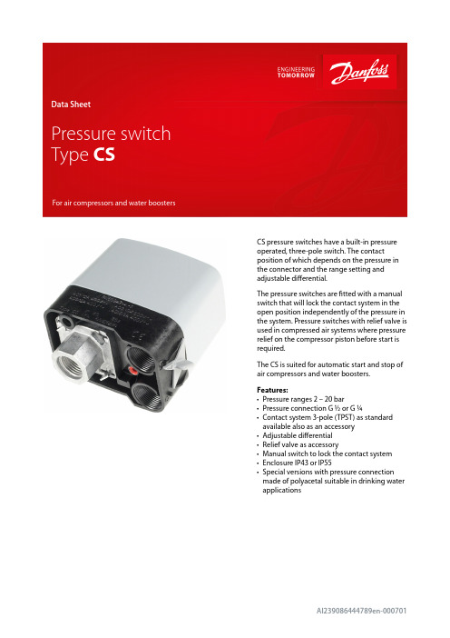
CS pressure switches have a built-in pressure operated, three-pole switch. The contact position of which depends on the pressure in the connector and the range setting and adjustable differential.The pressure switches are fitted with a manual switch that will lock the contact system in the open position independently of the pressure in the system. Pressure switches with relief valve is used in compressed air systems where pressure relief on the compressor piston before start is required.The CS is suited for automatic start and stop of air compressors and water boosters.Features:•Pressure ranges 2 – 20 bar•Pressure connection G ½ or G ¼•Contact system 3-pole (TPST) as standard available also as an accessory •Adjustable differential •Relief valve as accessory•Manual switch to lock the contact system •Enclosure IP43 or IP55•Special versions with pressure connection made of polyacetal suitable in drinking waterapplications1 2 3 4 5 6 7 8 910111213141516171819202122232425FunctionFigure 1: Design and function Danfoss31E58Slide ringEarth screw Cover screw CoverSpindleToggle armSnap springSnap armSwitch housing assy Self-tapping screwManual switchBaseGrubscrewStop pressure screwPressure padSpring retainerCompression springPressure shoeDiaphragmFlange, G ¼ or G ½CapDifferential armTension springDifferential pressure screwBracketThe pressure switch is built up of the following main elements: connector, diaphragm, snap system, main spring, differential spring and a 3-pole or one-pole contact system. The stop pressure must be set on the main spring and the difference between start and stop pressures on the differential spring.Pressure from the controlled system is led, via the connector, to the diaphragm. The diaphragm converts this pressure to a mechanical movement which is transferred by the snap system to the contact system. In this way, the contact system starts or stops a compressor/pump.Pressure switch, Type CSTechnical data(1)For water and seawater, max. 80 °C Figure 2: Resonance frequencySetting1.2.3.Figure 5: Installation Figure 6: Installationd > 8.5 mm – 1d ≤ 8.5 mm – 2031E0293turns, i.e. 4.5.InstallationRecommended orientationThe pressure switches will operate regardless of their orientation. However, to meet the enclosure requirements of IP43 and IP55, they must be mounted vertically with the connection downwards. The CS pressure switches are self-supporting (on the connection).Fitting a pressure relief valve:Remove the blanking plug Fit the pressure relief valve Fit the plastoform screwFitting screwed cable entriesThe accessory bag contains two sets of metal gaskets each with different internal diameters. These will give a sufficient cord relief if used correctly with the cable diameter concerned.Drain holeIf because of large temperature variations there is a risk of condensate forming in the pressure switch, a screwdriver can be used to make a drain hole in the enclosure.Figure 7: Drain holeDimensions [mm] and weights [kg]Figure 11: Dimensions [mm]Weight approx. 0.5 kgMains connectionFigure 12: 3-pole AC load Figure 13: 1-pole AC load Figure 14: 1-pole DC load(1)Preferred versionsAccessories and spare partsCertificates, declarations, and approvalsThe list contains all certificates, declarations, and approvals for this product type. Individual code number may have some or all of these approvals, and certain local approvals may not appear on the list.Some approvals may change over time. You can check the most current status at or contact your local Danfoss representative if you have any questions.Danfoss can accept no responsibility for possible errors in catalogues, brochures and other printed material. Danfoss reserves the right to alter its products without notice. This also applies to products already on order provided that such alterations can be made without subsequentialchanges being necessary in specifications already agreed. All trademarks in this material are property of the respective companies. Danfoss and the Danfoss logotype are trademarks of Danfoss A/S. All rights reserved.Online supportDanfoss offers a wide range of support along with our products, including digital product information, software,mobile apps, and expert guidance. See the possibilities below.The Danfoss Product StoreThe Danfoss Product Store is your one-stop shop for everything product related—no matter where you are in the world or what area of the cooling industry you work in. Get quick access to essential information like product specs, code numbers, technical documentation, certifications, accessories,and more.Start browsing at .Find technical documentationFind the technical documentation you need to get your project up and running. Get direct access to our official collection of data sheets, certificates and declarations, manuals and guides, 3D models and drawings, case stories, brochures, and much more.Start searching now at /en/service-and-support/documentation .Danfoss LearningDanfoss Learning is a free online learning platform. It features courses and materials specifically designed to help engineers, installers, service technicians, and wholesalers better understand the products, applications, industry topics, and trends that will help you do your job better.Create your Danfoss Learning account for free at /en/service-and-support/learning .Get local information and supportLocal Danfoss websites are the main sources for help and information about our company andproducts. Find product availability, get the latest regional news, or connect with a nearby expert—all in your own language.Find your local Danfoss website here: /en/choose-region .。
压力开关应用场景

压力开关应用场景压力开关是一种常见的电子元件,广泛应用于各个领域中。
它的作用是在受到一定压力或力量时,能够自动切换或控制电路的开关。
压力开关的应用场景非常丰富多样,下面将介绍几个常见的应用场景。
1. 工业自动化控制领域在工业自动化控制领域中,压力开关被广泛应用于各种机器设备和生产线中。
比如,在自动化生产线上,压力开关可以用来检测物体的压力变化,从而控制机器的运行状态。
当物体达到预设的压力值时,压力开关会自动切换电路,触发相应的动作,比如停止或启动某个机器设备。
2. 汽车制造领域在汽车制造领域中,压力开关被广泛应用于汽车的液压系统和空调系统中。
比如,在液压系统中,压力开关可以用来监测液压系统的压力变化,一旦压力超过安全范围,压力开关会自动切断电路,以防止液压系统发生故障。
在空调系统中,压力开关可以用来检测制冷剂的压力变化,一旦压力过高或过低,压力开关会自动切断电路,以保护空调系统的正常运行。
3. 家用电器领域在家用电器领域中,压力开关也有着广泛的应用。
比如,在洗衣机中,压力开关可以用来检测洗衣机内水位的变化,一旦水位达到预设的水位线,压力开关会自动切断电路,停止供水,以避免洗衣机溢水。
在空气净化器中,压力开关可以用来检测空气质量的变化,一旦空气质量下降,压力开关会自动切断电路,启动净化器工作,以净化室内空气。
4. 水利工程领域在水利工程领域中,压力开关被广泛应用于水泵系统和水位控制系统中。
比如,在水泵系统中,压力开关可以用来监测水泵的工作状态,一旦水泵出现异常,比如过载或缺水,压力开关会自动切断电路,以保护水泵的正常运行。
在水位控制系统中,压力开关可以用来检测水位的变化,一旦水位达到预设的上限或下限,压力开关会自动切断或接通电路,控制水位的稳定。
压力开关在各个领域中都有着广泛的应用。
它的作用是在受到一定压力或力量时,能够自动切换或控制电路的开关。
通过压力开关的应用,可以实现自动化控制、安全保护和节能减排等目标。
SMC ZISE80中文设定说明
ISE:Mpa,ZSE:Kpa P(可选):psi 迟滞模式,常开 迟滞模式,常开
2.5 ms 模拟
1/1000 0% 手动
OFF OFF
1) F0-单位选择功能
可选功能,部分型号无此功能。 单位不同,显示屏开显示的数值范围不同。 操作方法:按 和 键选择对应单位,按
键确认。
mmoorree::nn
设定值
模拟输出
按 键确认
自动移位输入
选择模拟输出将返回功能选择模 式
选择自动移位功能将进一步设定其功 能
mmoorree::nn
自动移位功能设定 按 和 选择自动移位功能
交替显示
自动移位显示
设定值
自动移位 按 键确认
归零移位选项 按 和 选择
mmoorree::nn
按键
设定输出类型-迟滞型/比较型 按 和 选择对应模式
进入 OUT1 规格设定 交替显示
输出类别
设定值
迟滞型
按键
设定输出模式-常开模式/常闭模式 按 和 选择常开/常闭
比较型 进入输出模式设定
交替显示
输出模式
设定值
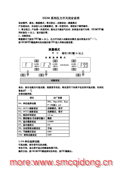
设定顺序:通电—测量模式—零点校正—功能设定—测量模式
产品通电后,自动进入压力测量模式,第一次使用时,请按如下顺序操作。
1、零点校正:产品第一次使用时,通电且不施加气压时,如果显示值不为零, 和 键
同时按住 1s 以上,显示值归零。
2、功能设定:
测量模式下按住 键 2s 以上,压力开关进入功能设定模式,显示屏显示为
果密码连续 3 次错误,屏幕显示“LoC”,按键锁定。
④ 密码修改方法:出厂时出示密码为“000”。
执行上述①②③步至密码输入正确,屏幕显示“UnL”时,
压力开关的工作原理

压力开关的工作原理压力开关是一种常用的工业自动化控制元件,广泛应用于各种机械设备和工艺过程中。
它能够根据被控制系统的压力变化来实现自动控制和保护功能。
下面将详细介绍压力开关的工作原理。
一、压力开关的结构组成压力开关通常由压力感应元件、弹簧机构、触点系统、外壳等组成。
1. 压力感应元件:压力感应元件是压力开关的核心部件,它能够将被测介质的压力转换成机械位移或电信号。
常见的压力感应元件有弹性膜片、弹簧管和差压传感器等。
2. 弹簧机构:弹簧机构主要用于提供压力开关的灵敏度和动作力。
根据不同的应用场景和要求,弹簧机构可以采用单弹簧、双弹簧或叶片弹簧等形式。
3. 触点系统:触点系统是压力开关的输出部分,它能够根据压力开关的动作状态进行开关控制。
触点系统通常由固定触点和动触点组成,其中固定触点固定在压力开关的外壳上,动触点则随着压力的变化而产生动作。
4. 外壳:外壳是压力开关的保护壳体,能够起到防尘、防水和防爆等作用。
外壳通常采用金属材料制成,具有良好的机械强度和耐腐蚀性能。
二、压力开关的工作原理压力开关的工作原理可以分为机械式和电子式两种。
1. 机械式压力开关的工作原理:机械式压力开关通过压力感应元件和弹簧机构实现对压力的感知和控制。
当被测介质的压力超过或低于设定的阈值时,压力感应元件会产生相应的机械位移,使得弹簧机构发生变形。
当弹簧机构的变形达到一定程度时,触点系统会发生动作,从而实现对被控制系统的开关控制。
以过压保护为例,当被测介质的压力超过设定的上限值时,压力感应元件会产生机械位移,使得弹簧机构变形。
当弹簧机构的变形达到一定程度时,触点系统会闭合,从而切断电源或触发报警信号,实现对被控制系统的保护。
2. 电子式压力开关的工作原理:电子式压力开关通过压力感应元件和电路系统实现对压力的感知和控制。
压力感应元件将被测介质的压力转换成电信号,经过放大、滤波和比较等处理后,驱动电路系统控制触点的开关状态。
电子式压力开关具有高精度、可调性好和抗干扰能力强等优点,广泛应用于精密仪器、自动化设备和工艺控制系统中。
- 1、下载文档前请自行甄别文档内容的完整性,平台不提供额外的编辑、内容补充、找答案等附加服务。
- 2、"仅部分预览"的文档,不可在线预览部分如存在完整性等问题,可反馈申请退款(可完整预览的文档不适用该条件!)。
- 3、如文档侵犯您的权益,请联系客服反馈,我们会尽快为您处理(人工客服工作时间:9:00-18:30)。
Pressure switch, type CS
Data sheet
Description
INDUSTRIAL CONTROLS IC.PD.P10.H 1.02 - 520B 2198
Pressure switch type CS is part of the Danfoss pressure control range. All CS pressure switches have a built-in pressure-operated, three-pole or one-pole switch, the contact position of which depends on
− the pressure in the connector − the range setting.
The pressure switches are fi tted with a manual switch that will lock the contact system in the open position independently of the pressure in the system.
CS product range
• Standard CS pressure switches − pressure connection: G ½ or G ¼
• CS pressure switches with special pressure connection made of polyacetal
− suitable in drinking water applications − pressure connection: G ½
Stop pressure range
Pressure switches are supplied in the following three versions:
− low-pressure, 2-6 bar
− intermediate pressure, 4-12 bar − high-pressure, 7-20 bar.
Contact system
Three-pole (TPST), contact system which opens on rising pressure. The contact system is touch-safe with open terminals, self-lifting terminal screws and star/slot screws.
Cable entry
The pressure switches have threads for two PG 16 screwed cable entries.
Screwed cable entries
Screwed cable entries are supplied with single pack CS pressure switches. Screwed cable entries for CS in industrial packs must be ordered separately under code no. 031E029366 containing seals and Pg 16 nuts.
Pressure relief valve
This valve relieves pressure on the compressor piston. It can be supplied as an accessory and must be ordered separately. The valve has an M10 x 1 external thread, union nut and cutting ring. The nut and cutting ring are both available in 6 mm and 1/4 inch sizes.
Manual switch
When the manual switch has been used to lock the contact system in its open position, the cover can be removed without the plant starting.
Enclosure
The enclosure is made of plastic (PA 6) and is obtain-able in IP 43 or IP 55 versions to IEC 529. A knockout in the base of the enclosure can be removed to provide a drain hole for condensate.
Application
The CS pressure switch is used for the auto-matic start and stop of − air compressors
− pumps for pressure water systems (pressure storage tanks).The CS with pressure relief valve is used in
compressed air systems where pressure relief on the compressor piston before start is required.
Approvals
EN 60 947-4,-5
D a n f o s s A /S 05-2005, I C -M C , m r
6
IC.PD.P10.H1.02-520B2198
Mains connection
3-pole
1-pole a.c.
1-pole d.c. load
Contact load
I e U e
AC-312 A 220 V ® 415 V
9 A 600 V DC-13/14
2 A
220 V
(3 contacts in series)
Dimensions
Weight approx. 0.5 kg。