压力开关规格书
QYK-02B(211NC)双接口单极常闭压力开关
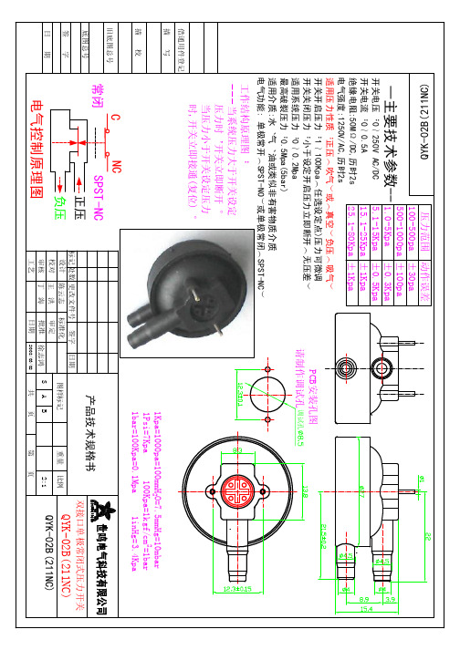
开关电压:0~250V AC/DC 5.1-15Kpa ±0.5Kpa 开关电流:0~0.5A 15.1-25Kpa ±1Kpa 绝缘电阻:50MΩ/DC,历时2s 25.1-80Kpa ±1Kpa 电气强度:1250V/AC,历时2s 适用压力性质:正压(吹气)或(真空)负压(吸气) 开关开启压力:1~100Kpa(任选设定点)压力可微调 开关关闭压力:小于设定开启压力立即断开(无压差) 适用系统压力:0~0.2Mpa 最高破裂压力:0.5Mpa(5bar) 适用介质:水、气、油或类似非有害物质介质 电气功能: 单极常开(SPST-NO)或单极常闭(SPST-NC)
双接口单极常闭式压力开关
重量
比例
QYK-02B(211NC)
电气控制原理图
审核 工艺
S
A 共
B 页 第
2:1
QYK-02B(211NC)
页
PCB安装孔图 请制作调试孔 调试孔
1Kpa=1000pa=100mmH2O=7.5mmHg=10mbar 1Psi=7Kpa 100Kpa=1kgf/cm2=1bar 1bar=100Kpa=0.1Mpa 1inHg=3.4Kpa
C 常闭
NC SPST-NC 正压 负压
产品技术规格书
标记 处数 更改文件号 签字 日期 设计 陈云志 标准化 审定 校对 王 洪 批准 徐志鸿 丁 海 日期 2008/03/02 图样标记
压力范围 动作误差 100-500pa ±30pa 500-1000pa ±100pa ±0.3Kpa
借通用件登记 描 写
描
校
旧底图总号
Hale Waihona Puke 底图总号 签 日 期 字QYK-02B(211NC)
压力开关规格书
工艺管 道材质
PIPE MAT'L
ITEM TAG No.
设定值 Setpoint 高 High 低 Low
℃
Mpa(G)
说明 NOTES:
编制
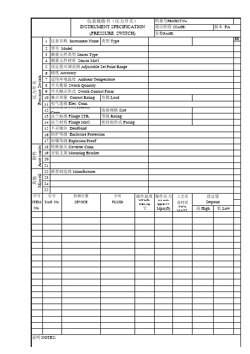
STRUMENT SPECIFICATION (PRESSURE SWITCH)
1 仪表名称 Instrument Name 类型 Type 2 3 4 5 6 7 8 9 10 11 12 13 14 15 16 17 18 19 20 21 22 23 24 25 型号 Model 测量元件类型 Senser Type 测量元件材质 Sensor Mat'l 设定值可调范围 Adjustable Set Point Range 精度 Accuracy 适用环境温度 Ambient Temperature 开关数量 Switch Quantity 开关触点形式 Switch Contact Form 触点容量 Contact Rating 负载 Load 电气连接 Elec. Conn. 过程连接形式 Process Conn. 连接规格 Size 法兰标准 Flange STR. 等级 Rating 法兰材质 Flange Mat'l 密封面形式 Facing 不灵敏区 Deadband 防护等级 Enclosure Protection 防爆等级 Explosion Proof 转换接头 Coverter Conn. 安装支架 Mounting Bracket
档案号PROJECT No: 设计阶段 STAGE: 页数PAGE:
版本 FA
REV
附件 Accessories 其他 Miscell
压力开关 Pressure Switch
推荐制造商 Manufacturer
压力开关说明7页

操作手册压力继电器(压力开关)YSJ-340系列一、概述YSJ-340系列压力继电器是一种超小型压力控制仪表,用于液压、气动系统的压力显示与控制,可替代德国贺德克HYDAC(贺德克)EDS300系列压力继电器。
该仪表采用了高精度压力传感器,电路部分以高性能单片机微处理器为核心,具有3位LED数字显示及轻触开关输入的人机界面、具有开关量(报警)输出及4~20mA模拟输出,是在机械继电器无法胜任的条件(如压力剧烈波动、强环境振动、高精度高速度控制、小体积等)下可靠工作的理想选择。
二、性能指标◇测量范围:0~1.6—0~60MPa◇电源电压:16~36VDC◇输出信号:(RL≤250Ω)◇接口螺纹:G1/4◇环境条件:环境温度:-20℃~60℃介质温度::-20℃~80℃存储温度:-40℃~125℃相对湿度:0~80%耐冲击:≤50g/ms耐振动:≤10g/(0~500HZ)◇输出信号精度:1.0◇过载压力:1.5%倍满量程压力◇最大功耗:≤3W触点容量:24VDC/1.2A(MAX)三、功能根据不同型号,装置可提供下列功能◇三位显示当前压力(正常工作)◇按压力、预设开关点输出开关量◇输出模拟量◇基本设定菜单◇提供四种不同输出模式:◇YSJ341带1路开关量输出(负载最大电流1.2A,无模拟量输出)◇YSJ342带2路开关量输出(负载最大电流1.2A,无模拟量输出)◇YSJ343带1路开关量输出(负载最大电流1.2A)和1路模拟量输出(4~20mA)◇YSJ344带2路开关量输出(负载最大电流1.2A)和1路模拟量输出(4~20mA)四、安装YSJ340可以通过压力管接头(DIN3852内螺纹G1/4),直接装在液压集成快上。
电气连接必须由国家认定合格的电工操作(参考中国电工国家标准规范)。
压力继电器的外壳必须同时良好的接地。
如安装在液压块里,块体通过液压系统接地时有保证的。
若用微型软管安装,客体必须单独接地。
高精度数字压力开关 56-ISE70 56-ISE75(H) 系列说明书
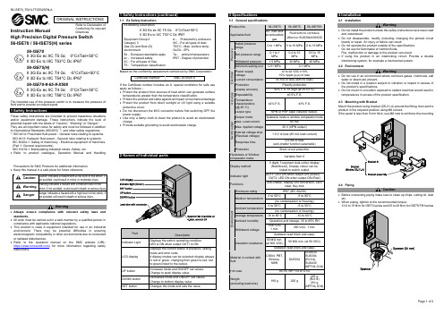
Instruction Manual56-ISE70 / 56-ISE75(H) series56-ISE70II 3G Ex ec IIC T5 Gc 0°C≤Ta≤+50°CII 3D Ex tc IIIC T53°C Dc IP6756-ISE75(H)II 3G Ex ec IIC T4 Gc -5°C≤Ta≤+50°C II 3D Ex tc IIIC T54°C Dc IP67 56-ISE70-#-65-#-X508II 3G Ex ec IIC T4 Gc 0°C≤Ta≤+50°C II 3D Ex tc IIIC T58°C Dc IP67The intended use of the pressure switch is to measure the pressure of fluid and to provide an output signal.These safety instructions are intended to prevent hazardous situations and/or equipment damage. These instructions indicate the level of potential hazard with the labels of “Caution,” “Warning” or “Danger.”They are all important notes for safety and must be followed in addition to International Standards (ISO/IEC) *1), and other safety regulations. *1)ISO 4414: Pneumatic fluid power - General rules relating to systems. ISO 4413: Hydraulic fluid power - General rules relating to systems.IEC 60204-1: Safety of machinery - Electrical equipment of machines. (Part 1: General requirements)ISO 10218-1: Manipulating industrial robots -Safety. etc.• Refer to product catalogue, Operation Manual and HandlingPrecautions for SMC Products for additional information. • Keep this manual in a safe place for future reference.CautionCaution indicates a hazard with a low level of risk which, ifnot avoided, could result in minor or moderate injury.WarningWarning indicates a hazard with a medium level of riskwhich, if not avoided, could result in death or serious injury.DangerDanger indicates a hazard with a high level of risk which, ifnot avoided, will result in death or serious injury.Warning• Always ensure compliance with relevant safety laws and standards.• All work must be carried out in a safe manner by a qualified person in compliance with applicable national regulations.• This product is class A equipment intended for use in an industrial environment. There may be potential difficulties in ensuring electromagnetic compatibility in other environments due to conducted or radiated disturbances.• Refer to the operation manual on the SMC website (URL: https:// ) for more information regarding safety instructions.1.1 Ex Safety Instruction Ex Marking DescriptionII 3G Ex ec IIC T5 Gc 0°C≤Ta≤+50°C II 3D Ex tc IIIC T53°C Dc IP67Equipment Group II Category 3Gas (G) and Dust (D) environmentEx - European standards apply ec - Increased safety IIC - For all types of GasT5 - Temperature classificationtc - Protected by enclosure IIIC - For all types of dust T53°C - Max. surface temp. Gc/Dc - EPLTa - ambient temperature IP67 - Degree of protectionBased on the conformity assessment carried out by SMC Corporation.Certificate Number:SMC 20.0029 XIf the Certificate number includes an X, special conditions for safe use apply as follows :-• Protect the product from sources of heat which can generate surface temperatures greater than the temperature classification.• Protect the product and cable against all impact or mechanical damage. • Protect the product from direct sunlight or UV light using a suitable protective cover.• Do not disconnect the M12 connector before first switching OFF the power supply.• Use only a damp cloth to clean the product to avoid an electrostatic charge.• Provide suitable grounding to avoid electrostatic charge.2 Names of Individual parts3 Specifications4 Installation4.1 InstallationWarning• Do not install the product unless the safety instructions have been read and understood.• Do not disassemble, modify (including changing the printed circuit board) or repair. An injury or failure can result.• Do not operate the product outside of the specifications. Do not use for flammable or harmful fluids.Fire, malfunction or damage to the product can result.• If using the product in an interlocking circuit: Provide a double interlocking system, for example a mechanical system. 4.2 EnvironmentWarning• Do not use in an environment where corrosive gases, chemicals, salt water or steam are present.• Do not install in a location subject to vibration or impact in excess of the product’s specifications.• Do not mount in a location exposed to radiant heat that would result in temperatures in excess of the product specification.4.3 Mounting with BracketMount the product using bracket (ZS-31-A) around the fitting, then set the product in the required position using M6 screws.If the panel is less than 5 mm thick, use M6 nuts to reinforce the mounting.4.4 PipingCaution• Before connecting piping make sure to clean up chips, cutting oil, dust etc.• When piping, tighten to the recommended torque:13.6 to 15 N•m for ISE70 series and 25 to 28 N•m for ISE75/75H series4.5 Wiring• Connections should be made with the power supply turned off.• Use a separate route for the product wiring and any power or high voltage wiring. Otherwise, malfunction may result due to noise.• If a commercially available switching power supply is used, be sure to ground the frame ground (FG) terminal. If the switching power supply is connected, switching noise will be superimposed and it will not be able to meet the product specifications. In that case, insert a noise filter such as a line noise filter/ferrite between the switching power supplies or change the switching power supply to the series power supply. • Connector mounting / removalAlign the cable connector key groove with the product connector key to insert and rotate the knurled part of the connector. M12 Connector Pin layout 56-ISE70/75(H)-##-43 No. Colour Function 1 Brown DC (+) 2 White OUT2 (PNP) 3 Blue DC (-) 4 Black OUT1 (NPN) 56-ISE70/75(H)-##-65 No. Colour Function 1 Brown DC (+) 2 White N.C. 3 Blue DC (-) 4 Black OUT1 (PNP) 56-ISE70/75(H)-##-27 / -67No. ColourFunction 1 Brown DC (+) 2 White OUT2 (NPN or PNP)3 BlueDC (-) 4 Black OUT1 (NPN or PNP)56-ISE70/75(H)-##-65-X508No. ColourFunction 1 Brown DC (+) 2 White OUT2 (4 to 20mA)3 BlueDC (-) 4 Black OUT1 (PNP)Power is supplied▼Measurement modeDetects pressure, displays values and performs switching. Other functions such as zero clear can also be set if necessary.▼ Initial settingSetting the output mode, LCD display colour, and response time.▼Pressure SettingInput of set value for pressure to perform switch output.▼Measurement mode5.1 Initial SettingPress and hold the SET button for 2 seconds or longer.The display shown right will appear to allow operating the initial setting mode.Finish initialization and return to measurement mode byno operation for 30 seconds or pressing the SET button for 2 seconds or longer.6 Pressure Setting• Pressure input mode for OUT1Press the SET button in measurement mode to display set values. [P_1] or [n_1] and the current set value will flash in turn. Press the SET button to display the next set value (Hysteresis: H_1). Press the UP or DOWN button to enter the value change mode.• When hysteresis mode is setIf the hysteresis mode is set, [H_1] and the set value of hysteresis will appear in turn after the setting for [P_1] or [n_1]. Press the SET button to return to normal measurement mode. Press the UP or DOWN button to enter the value change mode.If the hysteresis is set to 2 digits or less, the switch output may chatter if input pressure fluctuates near the set value.• When window comparator mode is setIf the Window comparator mode is set, [P_2] or [n_2] and the current set value will appear in turn after the setting for [P_1] or [n_1]. Press the SET button to display the next set value. (Hysteresis: H_1)Press the UP or DOWN button to enter the value change mode.Next, [H_1] and the set value of Hysteresis will appear in turn. Press the SET button to return to measurement mode. Press the UP or DOWN button to enter the value change mode.If the initialized value is normally open mode, [P_1] will appear, and [n_1] will appear if it is normally closed mode. The set pressure can be checked without holding or stopping switch output operation.7 Other Settings• Fine adjustment mode• Peak / Bottom value display • Key lock function • Zero Clear function .Refer to the operation manual on the SMC website (URL: https:// ) for further details of how to set these and other functions.8 Maintenance8.1 General MaintenanceCaution• Not following proper maintenance procedures could cause the product to malfunction and lead to equipment damage.• If handled improperly, compressed air can be dangerous.• Maintenance of pneumatic systems should be performed only by qualified personnel.• Before performing maintenance, turn off the power supply and be sure to cut off the supply pressure. Confirm that the air is released to atmosphere.• After installation and maintenance, apply operating pressure and power to the equipment and perform appropriate functional and leakage tests to make sure the equipment is installed correctly.• If any electrical connections are disturbed during maintenance, ensure they are reconnected correctly and safety checks are carried out as required to ensure continued compliance with applicable national regulations. How to reset the product after power cut or forcible de-energizing The setting of the product will be retained as it was before a power cut or de-energizing. The output condition is also basically recovered to that before a power cut or de-energizing, but may change depending on the operating environment.Therefore, check the safety of the whole installation before operating the product. If the installation is using accurate control, wait until the product has warmed up (approximately 20 to 30 minutes).9.1 Error Indication10 Limitations of Use10.1 Limited warranty and Disclaimer/Compliance Requirements Refer to Handling Precautions for SMC Products.11 Product DisposalThis product shall not be disposed of as municipal waste. Check your local regulations and guidelines to dispose of this product correctly, in order to reduce the impact on human health and the environment.12 ContactsRefer to or www.smc.eu for your local distributor / importer.URL : https:// (Global) https://www.smc.eu (Europe) SMC Corporation, Akihabara UDX15F, 4-14-1, Sotokanda, Chiyoda-ku, Tokyo 101 0021 Specifications are subject to change without prior notice from the manufacturer. © 2021-2022 SMC Corporation All Rights Reserved. Template DKP50047-F-085LError Error displayed Description Measures Overcurrent OUT1The load current applied to the switch output has exceeded 80 mA.Turn the power off and remove the cause of the over current. Then turn the power on. OvercurrentOUT2ResidualpressureerrorDuring zero clear operation, pressure over ±7%F.S. is applied. After 3 s, the mode will reset to the measurement mode. ±1 digit of the zeroclear range varies with individual product differences. Perform zero clear operation again after restoring the applied pressure to an atmospheric pressure condition.Pressure errorPressure has exceeded the upper limit of the set pressure range. Reset applied pressure to a levelwithin the set pressure range. Pressure has exceeded the lower limit of the set pressure range. SystemerrorDisplayed if an internal data error has occurred. Turn the power offand on again. If the failure cannot be solved, contact SMC. If the error cannot be reset after the above measures are taken, or errors other than the above are displayed, please contact SMC.。
消防用压力开关技术规格书
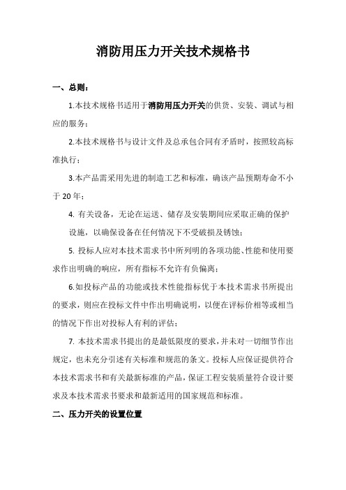
消防用压力开关技术规格书一、总则:1.本技术规格书适用于消防用压力开关的供货、安装、调试与相应的服务;2.本技术规格书与设计文件及总承包合同有矛盾时,按照较高标准执行;3.本产品需采用先进的制造工艺和标准,确该产品预期寿命不小于20年;4.有关设备,无论在运送、储存及安装期间应采取正确的保护设施,以确保设备在任何情况下不受破损及锈蚀;5.投标人应对本技术需求书中所列明的各项功能、性能和使用要求作出明确的响应,所有指标不允许有负偏离;6.如投标产品的功能或技术性能指标优于本技术需求书所提出的要求,则应在投标文件中作出明确说明,以便在评标价相等或相当的情况下作出对投标人有利的评估;7.本技术需求书提出的是最低限度的要求,并未对一切细节作出规定,也未充分引述有关标准和规范的条文。
投标人应保证提供符合本技术需求书和有关最新标准的产品,保证工程安装质量符合设计要求及本技术需求书要求和最新适用的国家规范和标准。
二、压力开关的设置位置1.在给水系统中的压力开关是用作启动/停止供水泵之用。
开关的运转范围和差幅应满足系统的控制要求;2.消火栓水泵可自动启动(由消防水泵出水干管上设置的压力开关、高位消防水箱出水管上的流量开关直接启动消防水泵),并同时将火警讯号送至消防控制室;3.临时高压系统的自动喷水灭火系统的开启由湿式报警阀的压力开关控制,其将信号接至消防控制中心并报警;三、压力开关的技术规格参数要求1.外观要求(1)压力开关表面不应有明显的锈蚀、涂层剥落、起泡、毛刺、结构松动等缺陷。
(2)压力开关上标示的文字符号和标志清晰、正确,标志内容应符合10.1.1要求。
2.额定工作压力压力开关的额定工作压力应不低于1.2 MPa.3.动作压力(1)普通型压力开关的动作压力为0.035 MPa-0.05 MPa.6.3.2 预作用装置压力开关动作压力为0.03 MPa~0.05 MPa.(2)特殊型系统压力开关的动作压力范围由厂家确定。
50dCE-50D.2-03压力开关规格书
第 1 页共 3 页 Page 1 of 3
6 5 4 3 2 1
修 改 Rev.
说 明 Description
编 制 PREP'D
校 对 CHK'D
审 核 APP'D
日期 DATE
格式编号:50D.2-03-2004
洛阳石油化工工程公司 中国石化集团 LUOYANG PETROCHE-
顾客要求clients仪表名称instrumentname类型type型号model测量元件类型sensertype测量元件材质sensormatl精度accuracy适用环境温度ambienttemperature开关数量switchquantity开关触点形式switchcontactform触点容量contactrating负载load电气连接elec
压力开关规格书
PRESSURE SWITCH SPECIFICATION 顾客要求 Client's 设计阶段 Phase
项目文件号 Proj.Doc.No.
专业文件号 Discipline Doc.No.
Rev.
LUOYANG PETROCHE洛阳石油化工工程公司 中国石化集团 工厂(公司)名称 Client: 项目名称 Project: 装置及(或)单元名称 Unit: LUOYANG PETROCHE洛阳石油化工工程公司 中国石化集团
压力开关规格书
16 防护等级 Enclosure Protection
17 防爆等级 Explosion Proof
18 转换接头 Coverter Conn.
19 安装支架 Mounting Bracket
Miscell Accessories
20
21 22 推荐制造商 Manufacturer
23
24
25 序号 位号
检测位置
介质
操作温度 操作压力 工艺管
设定值
ITEM TAG No. No.
SEVICE
FLUID
OPER. TEMP OPER. PRESS 道材质
Setpoint
℃
Mpa(G) PIPE MAT'L 高 High 低 Low
附件
其他
说明 NOTES:
编制
校对
审核
日期
3 测量元件类型 Senser Type
4 测量元件材质 Sensor Mat'l
5 设定值可调范围 Adjustable Set Point Range
6 精度 AccБайду номын сангаасracy
7 适用环境温度 Ambient Temperature
8 开关数量 Switch Quantity
9 开关触点形式 Switch Contact Form
压力开关 Pressure Switch
仪表规格书(压力开关) INSTRUMENT SPECIFICATION
(PRESSURE SWITCH)
1 仪表名称 Instrument Name 类型 Type
档案号PROJECT No: 设计阶段 STAGE: 页数PAGE:
压力开关规格书
1 仪表名称 Instrument Name 类型 Type 2 3 4 5 6 7 8 9 10 11 12 13 14 15 16 17 18 19 20 21 22 23 24 25 型号 Model 测量元件类型 Senser Type 测量元件材质 Sensor Mat'l 设定值可调范围 Adjustable Set Point Range 精度 Accuracy 适用环境温度 Ambient Temperature 开关数量 Switch Quantity 开关触点形式 Switch Contact Form 触点容量 Contact Rating 负载 Load 电气连接 Elec. Conn. 过程连接形式 Process Conn. 连接规格 Size 法兰标准 Flange STR. 等级 Rating 法兰材质 Flange Mat'l 密封面形式 Facing 不灵敏区 Deadband 防护等级 Enclosure Protection 防爆等级 Explosion Proof 转换接头 Coverter Conn. 安装支架 Mounting Bracket
档案号PROJECT No: 设计阶段 STAGE: 页数PAGE:
版本 FA
REV
附件 Accessories 其他 Miscell
压力开关 Pressure Switch
推荐制造商 Manufacturer
序号 No.
位号
检测位置 SEVICE
介质 FLUID
操作温度 操作压力
OPER. TEMP OPER. PRESS
工艺管 道材质
SS-1 压力开关产品说明书
Phone (504) 340-0055Fax(504) 340-0056SS-1 Pressure SwitchModel 4102Model 4102ItemQty.Qty DescriptionMaterial1Spring Spring Ca p 316L or ASTM-A-351 S.S.2A 1Spring (Blue)ASTM-4012B —Spring (Red)ASTM-4012C —Spring (Silver)ASTM-4012D —Spring (Gr een) optional Inconel X-7502E —Spring (Y ellow) ello (Y optional Inconel X-7502F —Spring (Purple) optional Inconel X-750Body For SS-1CF-8M St.Stl.Parts T ube T Acetate Butyrate Lock Ring AISI 316 St.Stl.Panel Mnt.Ring (Optional)AISI 316 St.Stl.Spring Plate AISI 316 St.Stl.8*4Spool O-ring Viton Spool For SS-117-4 PH St.Stl.10*2Shuttle Seal Viton 111Shuttle AISI 316 St.Stl.12*1Spool O-ring Viton 13*2Spool Sleeve Seal Viton 141Spool Spool Sleeve AISI 316 St.Stl.151 1.25”/.50” Piston AISI 316 St.Stl.16*1 1.25” Piston O-ring Viton 171 1.25”/.50”/.25” Base AISI 316 St.Stl.18*1.50” Piston O-ring Viton 191.25” Piston (Optional)AISI 316 St.Stl.20*1.25” Piston Backup eflon eflo T 21*1.25” Piston O-ring Viton 22—Repair Kit * Items Parts T ube ube T Not Supplied With Switches Using 3.0” or .187” Sensor Base.Parts List For Pressure Switch Model SS-11314151617191Repair GENERAL DESCRIPTION: The Ruelco ‘SS-1’ pneumatic pressure switch is a three way block and bleed valve that is operated by pressure acting on a piston opposing an adjustable spring force. It functions as either a normally closed or normally open valve, depending on through which of the two ports the instrument pressure is supplied. These ports are marked as ‘HI IN’ or ‘LO IN’ on the switch body. The output port, marked ‘OUT’ on the switch body, is the same for either mode of operation. Pressure applied to the sense port will cause the valve to operate. The Ruelco ‘SS-1’ pneumatic pressure switch can also be used as a two way bleed only valve in which case one of the ‘HI IN’ or ‘LO IN’ ports is plugged depending on whether the valve is to be used as a high or a low pilot.SS-1Pneumatic Pressure SwitchFEATURES• 316 stainless steel construction (models to N.A.C.E. MR0175 available).• Standard base range 10-10,000 p.s.i. (with 1/4" piston option).• Operating pressure range from .5 to 20,000 psi.• Block-and-bleed 3-way valve.• Holds constant and accurate set points.• Designed for 1% plus or minus repeatability on set points.• Minimum deadband between trip and reset pressure.• Spring may be replaced with instrument and sensing pressure present inthe sensor.• Vent above sensing piston prevents high pressure from entering instru-ment supply should a piston seal leak develop.• Optional tamper proof lock-out device available upon request.Valv V e T ypeT 3 or 2 Way Way Wa Set Point Deviation+1%Deadband 3 Way Way Wa 3% of Range 2 Way y Way Wa 5% of Range Range Max.Instr.Instr Press. 3 Way Way Wa 60 PSI 2 Wa y WayWa 150 PSI Cv Factor Factor Factor 0.160Ambient T emp em T .-20 to 250 deg.F Range -29 to 122 deg.CSwitch SpecificationsSensor T ype T PistonMax.P Oper.Oper ress.10,000 PSI (690 BAR)Burst Pressure 20,000 PSI (1380 BAR)emperatur em T e -20 to 250 Deg.F Range-29 to 122 Deg.C.25”/.50”/.25” 1.25”/.50”/.25” Switch Sensor Specifications * For Switch and 1.25/.50/.25 Sensor Base.A 2.12 (53.8)B (Max) 6.13 (155.7)C 1.32 (33.5)D 1.43 (36.3)E 1.22 (31.0)F 1.82 (46.2)G 1.23 (31.2)H 2.0 (50.8)(50.8)I 1/2” MNPT J1/4” MNPT Panel Mount Hole 1.875 (48.0)Valv V e Ports 1/4” FNPT Weight*Weig W 4.9 lbs.(2.3Kg)Dimensions Inch (MM)ITEM .QTY DESCRIPTION TERIAL TE M A 231Upper Housing 17-4 P .H.P St.Stl.241Piston Assembly17-4 P .H.P St.Stl.251SealViton 26Lower Housing 17-4 P .H.P St.Stl.27—Rep.Kit F/ 3.0” BaseItems 8,10,12,13,253.0" Sensor Base1LWhile this information is presented in good faith and believed to be accurate, Ruelco, Inc. does not guarantee satisfactory results from reliance upon such information. Nothing contained herein is to be construedas a warranty or guarantee, expressed or implied, regarding the performance, merchantability, and fitness with respect to the products. Ruelco, Inc. reserves the right, without notice, to alter or improve the designs or specifications of the products described herein.Ordering Code:4102 X X X X X X X X X 0 X 0 0 0 0BASE MODEL NUMBER Standard Corrosive Service - (-)N.A.C.E.Option - NSPRING CODE (see range chart)PISTON STON PIST CODE (see range chart)ITEM TY .QTY DESCRIPTION TERIAL TE M A 281Retainer Sleeve AISI 316 St.Stl.291.187” Sensor Base 17-4 P .H.P St.Stl.301.187” Piston 17-4 P .H.P St.Stl.311Back -Up RingGlass Filled T efloneflo T 321SealViton3319/16” Gland Nut AISI 316 St.Stl.3419/16” Gland Collar AISI 316 St.Stl.35—Rep.Kit F/ .187” BaseItems 8,10,12,13,31,32.187" Sensor BaseK 2.0 IN.(50.8 MM)L 3.75 IN.(95.2 MM)M 1/2” FNPT Weight*Weig W 8.5 lbs.(3.7 Kg.)* For Switch and 3.0” Sensor BaseSensor T ype T PistonMax.P Oper.Oper ress.20,000 PSI (1380 BAR)Burst Pressure 40,000 PSI (2760 BAR)emperatur em T e -20 to 250 Deg.F Range-29 to 122 Deg.C Sensor T ype T PistonMax.P Oper.Oper ress.5,000 PSI (345 BAR)Burst Pressure 10,000 PSI (690 BAR)emperatur em T e -20 to 250 Deg.F Range-29 to 122 Deg.C N 2.0 IN.(50.8 MM)P 2.57 IN.(65.3 MM)Q 9/16/ M/P Autoclave Weight*Weig W 5.0 lbs.(2.3 Kg.)* For Switch and .187” Sensor BaseSpring Codes (COLOR)ST AN DARD INCONEL SPRING SPRING B (Blue)G (Green)R (Red)Y (Y ello (Y w)S (Silver)P (Purple)Piston Diameter Piston CodeAvailab Avai A le Ranges - PSI (BAR)XXXXXXXXXXXXXXX3.0" 3.0" 3.0" 1.25"1.25"1.25".50".50".50".25".25".25".187".187".187"24.5-20(.03-1.4)4-40(.3-2.75)10-80(.7-5.5)10-115(.7-7.9)20-230(1.4 - 15.8)50-450(3.4 -31)200-750(13.8-51.8)500-1500(34.5-103.5)1000-3000(69-207)1000-3000(69-207)2000-5000(138-345)5000-10000(345-689)2000-5000(138-345)3500-9000(241-620)8500-20000(586-1380)1112233344OPTIONAL BASEOPTIONAL PISTONOPTIONAL BASESS SeriesPressure Switches SS-1 High Flow SS-2 Standard SS-2 High Flow(Pneumatic or Hydraulic)SS-1 Differential SS-2 Differential SS-4 Hydraulic BleedSS-E Electric SS-E Electric DifferentialSS-1 With Optional ScaleModel 4103SS-1 With Optional Scale Model 4103。
海尔-15A SPDT 银接触器压力开关规格说明书
5 to 30 psig
REPEATABILITY ±1.2 inHg ±0.15 psig
±1.0 psig
±5.0 psig
PROOF PRESSURE 29.9 inHg Vac 600 psig
600 psig
600 psig
PSW-584
100 to 500 psig
Enclosure: Switch actuator and bracket steel: irridite finish; adjusting cap and body: zinc alloy chromate finish; switch shield: Mylar®
Pressure Port: 1⁄4 MNPT
30 to 120 psig
±20 psig
600 psig
Comes complete with operator’s manual.
Ordering Examples: PSW-582, economical OEM pressure switch with adjustable range of 3 to 40 psig and 600 psig proof pressure.
To Order
MODEL NO. ADJUSTABLE RANGE
PSW-581
PSW-582
6 to 28 inHg Vac 1.5 to 3.5 psig
3 to 40 psig
PSW-583
30 to 150 psig
DEADBAND 3 to 14 inHg 0.5 to 1.7 psig
Electrical Connection: Screw terminals
- 1、下载文档前请自行甄别文档内容的完整性,平台不提供额外的编辑、内容补充、找答案等附加服务。
- 2、"仅部分预览"的文档,不可在线预览部分如存在完整性等问题,可反馈申请退款(可完整预览的文档不适用该条件!)。
- 3、如文档侵犯您的权益,请联系客服反馈,我们会尽快为您处理(人工客服工作时间:9:00-18:30)。
4 测量元件材质 Sensor Mat'l
5 设定值可调范围 Adjustable Set Point Range
6 精度 Accuracy
7 适用环境温度 Ambient Temperature
8 开关数量 Switch Quantity
9 开关触点形式 Switch Contact Form
10 触点容量 Contact Rating 负载 Load
介质 FLUID
操作温度 操作压力 OPER. OPER.
TEMP ℃
PRESS Mpa(G)
工艺管
道材质 PIPE MAT'L
版本 FA
RE
设定值 Setpoint 高 High 低 Low
附件
其他
说明 NOTES:Βιβλιοθήκη 编制校对审核
日期
11 12 13
电 过气 程连 连接 接形El式ec.PCroocnens.s C法o兰nn标. 准 Flange STR.
连接规格 Size 等级 Rating
14 法兰材质 Flange Mat'l
密封面形式 Facing
15 不灵敏区 Deadband
16 防护等级 Enclosure Protection
17 防爆等级 Explosion Proof
18 转换接头 Coverter Conn.
19 安装支架 Mounting Bracket
Miscell Accessories
20
21 22 推荐制造商 Manufacturer
23
24 25 序号 位号 ITEM TAG No. No.
检测位置 SEVICE
压力开关 Pressure Switch
仪表规格书(压力开关) INSTRUMENT SPECIFICATION
(PRESSURE SWITCH)
档案号PROJECT No: 设计阶段 STAGE: 页数PAGE:
1 仪表名称 Instrument Name 类型 Type
2 型号 Model
3 测量元件类型 Senser Type