S81S1001全彩接收卡说明书
中庆系统参数

产品名称产品型号中庆全彩发送卡 M81GCA01中庆全彩接收卡 S81S1001ZQ-V8-RV01 全彩接收卡ZQ-V8-TS01 全彩发送卡V8控制系统是提供一个开放的、全面的LED显示屏的基础系统平台。
V8控制系统面向通用屏市场的应用,它由功能强大的软件产品以及控制系统硬件产品组成。
V8最大特点在于,客户对于现在批量生产的产品不用作任何改动与调整的前提下,大幅度的提升产品性能,从而,获得突显产品的性能及成本优势。
特点:1. 超高刷新频率2. 输出分辨率:最大宽度2048,最大高度11523. V8系统在扫描屏应用时,扫描频率可显著高于普通通用屏,让扫描屏不再有扫描线4. 灰度等级可达655365. 支持接收卡级别的智能在线检测及故障报错6. 系统支持逐点亮度调整7. 功能升级8. Rohs认证,支持冗余结构,可靠性高9. 性价比高发送卡◆电气参数●工作电压:5±0.5V ●工作电流:2000mA●工作温度:摄氏0-60 度●工作湿度:5%-95%◆性能参数●控制接口支持USB2.0 ●数据接口支持DVI以及PC端 HDMI接口转接●支持参数固化●千兆输出接口●单卡帧频30Hz 时最大支持输出点数236 万点,单卡帧频60Hz 时最大支持输出点数131万点●支持最大宽度2048 像素,最大高度1152 像素●支持多种分辨率● 支持LED Manager 2010,LED Manager2012接收卡◆电气参数●工作电压:5±0.5V●工作电流:1500mA●工作温度:摄氏 0-60 度●工作湿度:5%-95%◆性能参数●控制最大高度256像素、最大宽度 512像素●支持宽度128以内的模组●支持1-16扫模组●支持100 级亮度调整以及红绿蓝 256 级色温调整、对比度调整、支持精确色温调整●支持在线升级固件,具有掉电再升功能。
●支持逐点亮度校正功能,每个接收卡最大支持 256*256 像素●时钟频率 18.8MHz 条件下, 静态屏 65536 级灰度等级,刷新频率最高达到 4200HzV8系统适用于所有通用显示屏应用,如户外广告屏、体育场馆屏、现场直播屏、舞台屏、演出租赁屏等。
清华永新卫星接收卡说明书

目录第一章清华永新卫星数据接收卡的介绍 (2)1.1产品简介 (2)1.2技术指标 (3)1.3系统配置要求 (4)1.4读出接收卡的卡号 (4)第二章卫星接收卡安装指南 (6)2.1硬件安装 (6)2.2软件安装 (6)第三章软件操作 (14)3.1I P接收 (14)3.2视频接收 (25)3.3视频功能应用 (30)第四章常用命令 (37)4.1查看网络配置 (37)4.2查看网络状态 (38)附录卫星卡常见故障 (39)第一章清华永新卫星数据接收卡的介绍1.1 产品简介清华永新卫星接收卡为北京清华永新电子有限公司自主研发并生产的产品。
北京清华永新电子有限公司通过了ISO9001质量体系认证,按照ISO9001标准的要求设计、生产了高标准、高质量的卫星接收卡,外观如下图所示:清华永新卫星数据广播接收卡安装于计算机的PCI槽上,与卫星天线的LNB相连,可以接收符合DVB-S标准的数据广播信号,并将数据恢复成IP包,传给操作系统。
该卡性能价格比高,操作简单且通用性强。
适用于各种基于IP的数据广播应用,如文件分发、远程教育、电子报刊、金融信息、视频点播以及高速因特网接入等等,是利用卫星通道的宽带特性实现宽带多媒体数据广播的最佳选择。
1.2 技术指标⏹产品符合DVB-S标准EN300 421规范⏹IP数据接收符合数据广播标准 ETSI/EN 301 192⏹符合DVB-S/MPEG-2标准⏹支持数据管道传送\数据流\多协议封装⏹符合PCI2.1总线规范⏹支持TCP/IP、UDP协议,可实现HTTP、FTP、SMTP高速下载⏹支持IP单播,多播接收及MAC过滤⏹同时解复用64路PID⏹自动搜索PID值⏹支持IP单目(Unicast)接收,多目(Multicast)接收⏹每路PID最大数据率为54Mbps⏹支持标清(SDTV)及高清(HDTV)数字电视节目播放⏹支持电视画面抓图⏹支持全流录制⏹支持定时录制,定时播放功能⏹支持童锁功能⏹支持22KHz及DiSEqC1.0,1.2标准开关⏹产品LNB电源支持13/18V<400mA⏹支持Windows 2000 sp4/ Windows 2003server/ Windowsxp sp2/vista(32)操作系统1.3 系统配置要求操作系统:⏹Windows 2000 SP4/Windows 2003server/Windows XPSP1 SP2/vista(32)(推荐使用WindowsXP系统)⏹Windows Direct X9.0推荐计算机配置:SDTV数字电视播放电脑配置要求:⏹Intel Pentium III 600 MHz CPU⏹128MB内存⏹32MB显存VGA显卡HDTV数字电视播放电脑配置要求:⏹Intel Pentium Ⅳ 2.0GHz CPU⏹256MB 系统内存⏹64MB显存以上高性能VGA卡1.4 读出接收卡的卡号在某些时候要确定DVB-S接收卡的卡号。
S81-M 背景抑制器带激光发射和飞行时间测量说明书
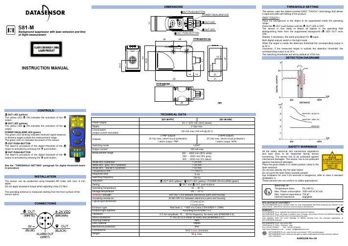
S81-MBackground suppressor with laser emission and timeof flight measurementThe yellow LEDThe yellow LED ON indicates the activation of theThe teach-in procedure of the digital threshold of theThe teach-in procedure of the digital threshold of theSee the “THRESHOLD SETTING” paragraph for digital threshold teach-The sensor can be positioned using threaded M5 holes with max. 6 mm.OUT push-button until theThe sensor is now ready to detect all objects in the operating fieldSAFETY WARNINGSAll the safety electrical and mechanical regulationsand laws have to be respected during sensorfunctioning. The sensor has to be protected againstmechanical damages. The sensor has to be protectedagainst mechanical damages.Place the given labels in a visible position close to thelaser emission.Do not look directly into the laser beam!Do not point the laser beam towards people!We DATASENSOR S.p.A. declare under our sole responsibility that these products are conform to theDATASENSOR S.p.A. will repair or replace, free of charge, any product found to be defective during the S81-M-PPC S81-M-NNCOUT LED (yellow) / OUT LED (yellow) / POWER ON-ALLARM (green)OUT and OUT push-buttons-10 … 50 °CS81-YDistance sensor with laser emission and time of flightmeasurementThe yellow LEDThe yellow LED ON indicates the activation of theThe teach-in procedure of the digital threshold of theThe teach-in procedure of the digital threshold of theSee the “THRESHOLD SETTING” paragraph for digital threshold teach-The sensor can be positioned using threaded M5 holes with max. 6 mmOUT push-button until theThe sensor is now ready to detect all objects in the operating fieldON). Repeat, if necessary, the same procedure for ouput.Both digital outputs switch in light mode: when the target detected is insideDETECTION DIAGRAMSSAFETY WARNINGSAll the safety electrical and mechanical regulationsand laws have to be respected during sensorfunctioning. The sensor has to be protected againstmechanical damages. The sensor has to be protectedagainst mechanical damages.Place the given labels in a visible position close to thelaser emission.Do not look directly into the laser beam!Do not point the laser beam towards people!Eye irradiation for over 0.25 seconds is dangerous; refer to class 2 standardWe DATASENSOR S.p.A. declare under our sole responsibility that these products are conform to theDATASENSOR S.p.A. will repair or replace, free of charge, any product found to be defective during the S81-Y-PPV S81-Y-NNVOUT LED (yellow) / OUT LED (yellow) / POWER ON-ALLARM (green)OUT and OUT push-buttons-10 … 50 °C。
SR8全向型双频有源RFID接收终端产品手册说明书

深圳市思卡乐科技有限公司Shenzhen RFscaler Technology Co., Ltd. SR8全向型双频有源RFID 接收终端——————————————产品概述 SR8系列全向型双频有源RFID 接收终端,是专门针对智慧城市RFID 定位管理、巡逻智能签到、学生校内外定位等应用而开发的高性能户外有源RFID 接收设备。
具有GPRS 或以太网(LAN )通讯接口、2.4G 和433M 双频RFID 、磷酸铁锂备用电池、IP65防护等级、远程固件升级等功能和特点,适合于户外安装使用。
SR8系列全向型双频有源RFID 接收终端,具有双频的有源RFID 读卡,2.4G 适合于人员和低速车辆的远距离RFID 定位,433M 适合于城市街道的高速车辆远距离RFID 定位,可以做到一个接收器,满足多种场合应用。
————————产品应用RFID 电动车管理系统 智慧城市物联网智能管控 巡警巡逻考勤系统 小区巡逻考勤系统 资产管理系统 集装箱管理系统 养老院定位管理系统 景区游客流量管理系统 高速公路二义路径收费系统——————————————产品特性—————————————————◆ 具有2.4GHz 和433MHz 双频的距离RFID 读卡功能; ◆ 双频的RFID 采用独立的高增益全向型天线设计;◆ 先进的防碰撞技术,同时可识别200张卡@2.4GHz ,50张@433MHz ;◆ 识别RFID 标签的距离(空旷可视直线距离):50米以上@2.4GHz ,130米以上@433MHz ; ◆ RFID 读卡的距离,可以通过云平台远程和PC 软件现场两种方式来设置和调节,满足不同场合的应用需求(仅针对带衰减器的型号有效); ◆ 连接数据中心的网络通信接口有GPRS 和以太网(LAN )两种方式可选; ◆ 网络协议采用稳定易用、省流量的TCP 协议,支持Socket 网络接口; ◆ 采用成熟可靠的应用层通信协议栈,保证设备与数据中心通信的稳定性; ◆ 通讯采用独有加密计算与认证方式,确保数据安全,防止链路窃听与数据破解; ◆ 读卡的数据上传数据中心,提供是否过滤的设置功能; ◆ 具有通过远程固件升级功能,方便设备维护; ◆ 具有设备异常或故障的实时在线报警监控功能;◆ 采用大容量磷酸铁锂备用电池,充电循环2000次,掉电可持续工作13小时以上(仅针对带备用电池的型号有效); ◆ 采用工业级的抗干扰和防雷能力设计,符合GBT 17626.5-2008浪涌(冲击)抗扰度试验; ◆ 外壳采用抗紫外线材料,通过YDT1537-2006通信系统户外机柜标准的检验测试; ◆ 外壳采用IP65的防护等级设计,适合户外环境使用; ◆ 整个产品设计轻便,安装简单,容易维护。
诺瓦科技LED全彩接收卡A4s参数设置说明书英文版

A4s Receiving CardDocument Version:V1.2.0Copyright © 2018 Xi’an NovaStar Tech Co., Ltd. All Rights Reserved.No part of this document may be copied, reproduced, extracted or transmitted in any form or by any means without the prior written consent of Xi ’an NovaStar Tech Co., Ltd.TrademarkSpecifications Change Historyis a registered trademark of Xi’an NovaStar Tech Co., Ltd.StatementYou are wele to use the product of Xi’an NovaStar Tech Co., Ltd. (hereinafter referred to as NovaStar). This document is intended to help you understand and use the product. For accuracy and reliability,NovaStar may make improvements and/or changes to this document at any time and without notice. Any problem in use or a n y good suggestion, please contact us through ways provided in the document. We will do our utmost to solve the problems and adopt the suggestions after evaluation as soon as possible.Change HistoryVersion Release Date DescriptionV1. 2 .0 201 8 - 0 8 - 10 O p timized the quick seam correction function. V1.1.02018 - 01 - 25Added the following functions:●LVDS transmission ( S upported by dedicatedfirmware program ) .●Image rotation in 90 ° increments .V1.0.1 2017 - 07 - 27 Optimized the data interface information. V1.0 .0201 6 - 10 - 25First release.Specifications ContentsContentsChangeHistory (ii)1 Safety ............................................................................................................................. .. 12 Overview ........................................................................................................................ .. 23Features ......................................................................................................................... .. 33.1 Improvement in Display Effect ..................................................................................................................... 33.2 Improvement in Maintainability .. (3)3.3 Improvement in HardwareReliability (4)3.4 Improvement in SoftwareReliability (5)4 Hardware ....................................................................................................................... .. 64.1 Appearance ..................................................................................................................................................64.2 Dimensions (6)4.3 Indicators (7)4.4 Definition of Data Interface( Top ) (8)4.1.1 24-Group ParallelData (8)4.1.2 64-Group SerialData (11)4.1.3 Extended FunctionsDesign (14)5 FirmwareUpdate (16)6 Applications (17)7 Specifications (18)A Abbreviation (19)B Terms (20)1 Safety1 Safety’s storage, transport, installation and use safety. Safety instructions areapplicable to all personnel who contact or use the product. First of all, payattention to following points.●Read through the instructions.●Retain all instructions.●ply with all instructions.Storage and Transport Safety●Pay attention to dust and water prevention.●Avoid long-term direct sunlight.●Do not place the product at a position near fire and heat.●Do not place the product in an area containing explosive materials.●Do not place the product in a strong electromagnetic environment.●Place the product at a stable position to prevent damage or personalinjury caused by dropping.●Save the packing box and materials which will e in handy if you ever haveto store and ship the product. For maximum protection during storageand shipping, repack the product as it was originally packed at the factory. Installation and Use Safety●Only trained professionals may install the product.●Plugging and unplugging operations are prohibited when the power is on.●Ensure safe grounding of the product.●Always wear a wrist band and insulating gloves.●Do not place the product in an area having frequent or strong shake.●Perform dust removing regularly.●Contact NovaStar for maintenance at any time, rather than have theproduct disassembled and maintained by non-professionals withoutauthorization.●Replace faulty parts only with the spare parts supplied by NovaStar.2 Overview2 OverviewA4s is a high-end receiving card developed by NovaStar, featuring small size and large loading capacity with a single card loading up to 256 x 256(PWM IC) pixels.A4s supports pixel level brightness and chroma calibration by working with NovaLCT and NovaCLB to realize calibration on each pixel. It can effectively remove color difference and greatly improve LED display image consistency, presenting smoother images to users. In addition, it also supports image rotation in 90° increments, creating richer images and improving visual experiences.Software and hardware designs of the A4s concern the user deployment aswell as operating and maintenance scenarios, enabling easier deployment, more stable operating and more efficient maintenance.Advanced hardware design:●The small-size hardware design is applicable to scenarios of small cabinetspace and small pixel pitch.●Use high-density connector which is resistant to dust and vibration andfeatures high stability and high reliability.●Assembly network transformer features simple design and improvedmagnetic patibility, helping user’s products to successfully pass the EMC authentication.Useful software design:●Support for LVDS transmission (Supported by dedicated firmwareprogram).●Support for smart module (Supported by dedicated firmware program).●Support for quick seam correction.●Support for 3D function.●Support for pre-stored image setting of the receiving card.Supporting quick seamcorrection●Support for module Flash management.●Supports monitoring voltage and temperature of itself without using otherperipherals.●Support for monitoring of Ethernet cable munication status (Supported bydedicated firmware program).●Support for 5-pin LCD module.●Support for image rotation in 90° increments.3.2Improvement in MaintainabilitySupporting the smart module(Supported by dedicated firmware program)The smart module is posed of Flash and MCU. Flash could store calibration coefficients and module information. MCU could municate withthe receiving card to realize monitoring over temperature, voltage and wiring munication status for the module. Working with the driver chip, A4s supports open circuit detection on LED.The smart module could make monitoring unit smaller, requiring no independent monitoring card3Features3.1 Improvement in Display EffectFeatures Descriptionand saving cabinet space.Supporting LVDS transmission (Supported by dedicated firmware program)The transmission mode of low-voltage differential signaling (LVDS) is used, which reduces the number of data cables that connect the receiving card's HUB board to the module, increases the transmission distance, improves the signal transmission quality, and better stabilizes the image output.Supporting setting of images pre-stored of the receiving card On NovaLCT, the specified images could be set as the screen startup image and images used when the Ethernet cable is disconnected or no video source signal is available.Supporting module Flash management On NovaLCT, lamp panel Flash could be managed.Supporting monitoring voltage and temperature of itself The voltage and temperature of the receiving card itself can be monitored without using other peripherals. The monitoring data can be checked on NovaLCT.Supporting LCD module Supports NovaStar's general 5-pin LCD module. The LCD module is connected to the HUB board to display temperature, voltage, single operating time and total operating time of the receiving card.Support one-click application of calibration coefficient in module Flash In the event of network outage, hold down the selftest button to read the calibration coefficient in module Flash back to the receiving card.3.4 Improvement in Software ReliabilityFeatures DescriptionSupp o rting readback of firmware version On NovaLCT, the firmware versions of the receiving card can be read back.Supporting readback of configuration file ●On NovaLCT, the receiving card configuration parameters can be backed up to the receiving card.●On Nova L CT, the receiving card configuration parameters can be read back.3.3Improvement in Hardware ReliabilityFeatures DescriptionSupporting d ual-p ower backup detection Two power supplies could be simultaneously connected, and operating status of the power supplies could be detected.Supporting loop backup HUB’s Ethernet port improves the reliability for the serial connection of the receiving c ard through main and standby redundant mechanism. Among the main and standby serial connection lines, if one fails, the other will begin to work to ensure the normal operation of the display.优选Board thickness is not greater than 2.0 mm, and the total thickness (board thickness + thickness of both front panel and back panel) is not greater than 7.5 mm.Unit of the dimension chart is “mm ”. Ground connection is enabled for location hole (GND).4Hardware4.1 AppearanceProduct images provided in this file are for reference only, and the actual productsshall prevail.Models of the high-density receptacle and plug used by A4s are shown in Table 4-1. Table 4-1 Model of high-density connectorType Brand Material Code Receptacle Amphenol FCI 10140609 - 121802 L F PLUGAmphenol FCI10140607 - LF 1218024.2 Dimensions4.3 Indicators4.4 Definition of Data Interface ( Top )Indicator StatusDescriptionStatusindicator (green)Flashing every other 1s.The receiving card works normally, Ethernet cable connection is normal, and video source input is available.Flashing every other 3s.The receiving card works normally, whilethe Ethernet cable connection is abnormal.The receiving card works normally, Ethernetcable connection is normal, while no video source input is available.Rapidly flashing every other 0.5s.Program loading fails in normal operating state, ing to the backup operating state.Rapidly flashing for 8 times every other 1s. The receiving card is in the Ethernet port backup status and the backup is effective.Powerindicator (red)Always on It is always on after the power is on.ash i ng f or 3 ery other 3s.4.4.1 24-Group Parallel DataNCNC68565557NC NC47 48 GNDOperating indicator DCLK4546 OE_BLUENC 113 114 NCNC 115 116 NCGND 117 118 GNDGND 119 120 GND 4.4.2 64-G roup Serial DataData61 Data6354565759NCNCNC bit netNC4041CExtended Functions DescriptionRemended Module Flash Reserved RFU5RFU7Remended SmartModule InterfaceRFU6select only one interface from either the Remended Smart Module Interface or the Remended Module Flash Interface at the same time.5 FirmwareUpdate5Firmware UpdateStep 1 Visit .novastar.tech to download the firmware update package and save it to PC. Step 2 Run NovaLCT and choose User > Advanced Synchronous System User Login to log in.Step 3 Type the secret code "admin " to enter the program loading page.Step 4 Click Browse to select the program (the firmware update package you saved on PC) path and then click U pdate.Step 5 Click Refresh to check current hardware version information.6 Applications优选6Applications A4s is applied to LED display synchronous system which is generally posed ofthe LED display, HUB board, receiving card, video controller and controller peripheral. The receiving card is connected to the display over a HUB board. Synchronous system requires connecting a puter to display the pute r’s images and texts on the LED screen. Structure of the synchronous system is as shown in the following figure.Input voltage DC 3.3 V–5.5 V优选7 Specificati ons A Abbre viatio nRated current0.5 ARated power consumption 2.5 W Operating temperature -20°C –70°C Storage temperatureOperating humidity 10%RH –90%RHDimensions 70.0 mm × 45.0 mm × 7.3 mm Net weight 17.3 g● RoHS● EMC Class BPackingAn antistatic bag and anti-collision foam are prepared for each receiving card.Dimensions of the packing box: 378 mm × 190 mm × 120 mm, each of 40 receiving cards.- 25 °C – 125 °CCertification s7SpecificationsA AbbreviationEEMC Electro m a gnetic patibilityFFPGA Field -P rogrammable Gate ArrayLLED Light Emitting DiodeMMCU Microcontroller UnitRRCFG Receiving Card ConfigurationB TermsB T ermsCalibration coefficientCalibration system generates a group of values for each LED lamp, including information about brightness and chroma. After display calibration, the calibration values of each lamp are just the calibration coefficient.Smart moduleThe smart module is posed of Flash and MCU.Flash could store calibration coefficients and lamp panel information. MCU could municate with the receiving card to realize monitoring over temperature, voltageand wiring munication status, Working with the driver chip, A4s supports opencircuit detection on LED.The smart module could make monitoring unit smaller, requiring no independent monitoring card and saving cabinet space.。
海星达iRTK系列产品使用说明书

2023年06月遥控接收模块CN1001安装使用手册说明书

2023年06月遥控接收模块——CN1001——安装使用手册Version:1.0深圳市丛文安全电子有限公司Shenzhen CONWIN Security Elec.Co.Ltd.·版权说明本手册版权归深圳市丛文安全电子有限公司所有。
深圳市丛文安全电子有限公司保留一切版权。
除了版权法允许的使用方法之外,未经事先许可,任何人不得复制、改编或翻译。
·保证说明本手册所含之内容如有改变,恕不另行通知。
深圳市丛文安全电子有限公司对由于本手册的错误而引起的损害不承担责任,对由于提供或使用本手册而随带发生的损害亦不承担责任。
·商标说明丛文®是深圳市丛文安全电子有限公司的注册商标。
CONWIN®是深圳市丛文安全电子有限公司的注册商标。
目录产品概述 (4)结构描述 (4)布撤防遥控器按键 (7)使用说明 (7)性能指标 (8)接不同报警主机安装要点 (9)1、科隆CP428/CP816主机 (9)2、博世CMS6/8/40主机 (9)3、DSC主机 (9)4、CK主机 (10)5、枫叶SP系列/7x8+系列主机 (10)6、Vista主机 (10)7、博世IP7400/DS7400主机 (10)8、EL-ST2008主机 (10)9、XR-303B主机 (10)10、Inanter-NT1/NT3主机 (10)11、Risco-LightSYS主机 (10)产品概述CN1001是专门配合报警主机的遥控接收模块,可实现对报警主机进行遥控布/撤防操作,还支持紧急报警和巡更功能。
最多支持16个遥控器,适用遥控器:CN0001、CN0002、CN0003、CN0004。
通过G/Y接口连接报警主机键盘总线。
支持的报警主机:丛文主机、科隆CP428/816主机、DSC系列主机、CK系列主机、博世CMS6/8/40/CC408/IP7400/DS7400主机、枫叶SP系列/SP7x8+系列主机、霍尼Vista系列、Omini主机、EL-ST2008主机、希锐XR-303B主机、Inanter-NT1/NT3主机等;独立使用:遥控器按键触发继电器(PAT、PAT)动作2秒,用以激活其它设备结构描述一、与主机接线模块R/B/G/Y端子连接兼容的报警主机键盘口,且必须与主机键盘并接在相同端子上(博世IP7400/DS7400主机也可以连接在辅助总线,使用11-15号键盘)二、拨码开关(拨向“ON”描述为ON,反之为OFF)1、拨码开关1-4:用于主机类型选择。
诺瓦科技Micro LED全彩接收卡A9s用户使用技术文档说明书
版权所有 © 西安诺瓦电子科技有限公司 2018 。
保留一切权利。
非经本公司书面许可,任何单位和个人不得擅自摘抄、复制本文档内容的部分或全部,并不得以任何形 式传播。
商标声明声明 欢迎您选用西安诺瓦电子科技有限公司(以下简称诺瓦科技)的产品,如果本文档为您了解和使用产品 带来帮助和便利,我们深感欣慰。
我们在编写文档时力求精确可靠,随时可能对内容进行修改或变更, 恕不另行通知。
如果您在使用中遇到任何问题,或者有好的建议,请按照文档提供的联系方式联系我 们。
对您在使用中遇到的问题,我们会尽力给予支持,对您提出的建议,我们衷心感谢并会尽快评估采 纳。
A9s 接收卡产品说明书 更新记录 更新记录产品说明书更新记录目录1安全说明 (1)1.1存储和运输安全 (1)1.2安装和使用安全 (1)2概述 (2)3产品特性 (3)3.1提升显示效果 (3)3.2提升可维护性 (3)3.3提升硬件可靠性 (4)3.4提升软件可靠性 (4)4硬件结构 (6)4.1外观 (6)4.2尺寸图 (6)4.3指示灯 (7)4.4数据接口定义(T op) (8)4.4.132组并行数据接口 (8)4.4.264组串行数据接口 (11)4.4.3扩展功能参考设计 (14)5软件结构 (15)6典型组网 (16)7产品规格 (17)A缩略语 (18)B术语 (19)产品说明书1安全说明1安全说明本章介绍A9s接收卡的安全说明,目的是保证产品的存储、运输、安装和使用安全。
安全说明适用于所有接触和使用产品的人员。
首先请注意以下几点:●请阅读所有说明。
●请保留所有说明。
●请遵循所有说明。
1.1存储和运输安全●请注意防尘防水。
●请避免阳光长时间直射。
●请勿靠近热源和火源。
●请勿放置在易爆气体环境中。
●请勿放置在强电磁环境中。
●请将产品放在稳固的位置,以防坠落造成产品损坏或人身伤害。
●请保存包装箱和包装材料。
存储和运输产品时可以使用。
- 1、下载文档前请自行甄别文档内容的完整性,平台不提供额外的编辑、内容补充、找答案等附加服务。
- 2、"仅部分预览"的文档,不可在线预览部分如存在完整性等问题,可反馈申请退款(可完整预览的文档不适用该条件!)。
- 3、如文档侵犯您的权益,请联系客服反馈,我们会尽快为您处理(人工客服工作时间:9:00-18:30)。
1.产品概述
1.1 产品应用
接收卡是LED屏控制系统中显示数据的接收设备。
S81S1001接收卡支持各种通用架构LED屏的控制。
1.2 功能特点
●千兆技术
●支持单双色、全彩实像素及虚拟显示屏
2.产品外观
2.1全彩接收卡S81S1001实物图
图2-1
3.接口信号定义
3.1接口说明
●PORT A:级联信号输入输出口,靠近电源端。
用于连接发送卡或下级接收卡。
●PORT B:级联信号输入输出口,与A功能相同,用于连接发送卡或下级接收卡。
●双排针接口1:用于本地控制输出,与通用转接卡相连。
●双排针接口2:用于本地控制输出,与通用转接卡相连。
●按键:用于测试显示屏。
系统正常连接上电后,拔掉接收卡的A/B端口,按此按键,
进入测试模式,模组将呈现斜线、亮度渐变、红、绿、蓝、白等测试图像。
电源输入接口:两种形式,单排插座和栅栏式电源座。
3.2 接口信号定义
全彩接收卡包含两种形式级联输入输出接口和两个本地输出接口。
级联输入输出有两种接口形式,分别为RJ45和双排孔,双排孔便于用户自行焊接连接器进行连接,如图3-1 JP_0所示;本地输出接口形式为两个对称的双排针,均为50PIN的排针,如图3-1 JP_1、图3-1 JP_2所示。
下面这些接口的信号定义进行详细说明。
图3-1 全彩接收卡接口示意图
3.2.1 JP_0信号定义
图3-2 JP_0信号定义
3.2.2 JP_1、JP_2信号定义
GND GND GND DA31VCC VCC NC DA30DA29DA27DA25DA23DA21DA19DA17DA15DA13DA11DA9DA7DA5DA3DA1DA28DA26DA24DA22DA20DA18DA16DA14DA12DA10DA8DA6DA4DA2DA0C_1A_1D_1B_1LD_1OE_1VCC VCC
CK_1GND GND GND
GND GND GND DA63DA61DA59DA57DA55DA53DA51DA49DA47DA45DA43DA41DA39DA37DA35DA33D_2B_2LD_2OE_2VCC VCC
VCC
VCC NC DA62DA60DA58DA56DA54DA52DA50DA48DA46DA44DA42DA40DA38DA36DA34DA32C_2A_2CK_2GND GND GND
图3-3 JP_1信号定义 图3-4 JP_2信号定义
3.3指示灯说明
全彩接收卡共有三个指示灯,两个绿色指示灯分别为电源(POWER )指示灯和状态(STATE )指示灯,一个红色指示灯错误(ERROR )指示灯。
● POWER :电源指示灯,绿色。
正确连接电源时,电源指示灯常亮,否则电源指示灯灭。
● STA TE :状态指示灯,绿色。
A 或B 有信号输入,则状态指示灯闪烁; A 和B 均无信
号输入,状态指示灯常亮;硬件故障,则状态指示灯灭。
● ERROR :错误指示灯,红色。
A 或B 两者之一输入的有误码,则错误指示灯闪烁;A
或B 均无误码,错误指示灯灭。
错误指示灯常亮,表示固件故障或特殊情况的指示。
4. 参数指标
4.1性能参数
● 超大带载量
● 高刷新频率
采用特殊处理算法,获得数倍于于普通方案的刷新率。
● 亮度校正功能
支持箱体内红、绿、蓝分别256级整体的亮度调整,同时支持最大256×256像素的逐点的256级亮度校正。
●安全可靠在线升级固件
升级过程中接收卡断电或通信中断,恢复正常后可以再次在线升级固件;完善的校验机制确保升级成功。
●支持在线检测功能
4.2电气参数
●工作电压:5±0.5VDC
●工作电流:1500mA
●工作温度:0~60ºC
●工作湿度:5%~85%RH
5.尺寸图
图5-1全彩接收卡正面尺寸图
图5-2全彩接收卡侧面尺寸图
6.注意事项
为了便于理解和引起您的注意,当涉及产品安全或需要关注的信息时我们会在本节中按下列等级和特别的警示用语向您提示,这些特别的警示用语表示方法如下:
【危险】--表示对高度危险要警惕
【警告】--表示对中度危险要警惕
【注意】--表示对轻度危险要关注
本节中为您提供的安全信息并不是全部的,为了您的安全和利益,我们会根据需要将部分安全信息编排到说明书的前面章节中,不论这些安全信息置于何处,为了您的安全,您均应仔细阅读。
同样,除了以特别的警示用语提出的注意事项外,对于说明书中的其他内容和介绍,您亦应予以同样的重视。
6.1工作环境
【危险】
●为了避免意外故障,控制器应在限定条件之内工作详见4.2电气参数。
●为防止起火或触电事故,请不要将系统暴露在雨(水)中或潮湿环境里。
●请将系统放置在通风良好之处,以防过热。
【警告】
●为防止触电,请使用三相插头电源,并保证接地的可靠性。
●为了防止短路造成烧毁,请不要将系统直接放置在导电的物品上。
如果需要放置,请使
用绝缘物质隔离。
●使用系统前,请检查当地电压、开关电源电压是否符合系统要求,电源正负极定义是否
和系统一致。
●如果发生问题,请您不要对系统板进行加焊、改焊、或者拆除板上组合部分,或者拆除
插在芯片座上的芯片。
【注意】
●两次开关控制器的间隔时间建议为至少为10秒。
●为了以后系统维修,请您不要撕毁或者涂改系统上的标签。
6.2运输
●运输时应放在包装箱内,并使用封闭式货箱搬运,人工搬运时注意轻拿轻放。
6.3贮存
●贮存时应放置在干燥的环境中,并避免强光直射。
●贮存时远离易燃易爆物品,避免一切不安全的情况发生。