泰克高压差分探头P52XXA
高压差分探头数据参考手册说明书

N2790A 100 MHz, N2791A25 MHz and N2891A 70 MHzHigh-voltage DifferentialProbesData SheetOscilloscope users often need to makefloating measurements where neitherpoint of the measurement is at earthground. Use the N2790A, N2791A orN2891A high-voltage differential probeto make safe and accurate floatingmeasurements with an oscilloscope.The N2790A, N2791A and N2891Ahigh-voltage differential probes allowconventional earth-grounded Agilentoscilloscopes to be used for floatingsignal measurements.2With a differential amplifier in the probe head, the N2790A is rated to measure differential voltage up to 1,400 VDC + peak AC with high CMRR (common mode rejection ratio) of >50 dB at 1 MHz. The N2791A and N2891A can measure differential voltage up to 700 V and 7 kV differential or common mode respectively. The N2790A, N2791A and N2891A differential probe offers sufficient dynamic range and bandwidth for your application to make the floating measurements found in power electronics circuits safely and accurately.The N2790A, N2791A and N2891A differential probe offers user selectable attenuation settings that make it highly versatile, allowing it to be used for a broad range of applications. The probe comes with probe tip accessories for use with both small or large components in tight places. The N2790A and N2891A also have an overrange indicator which alerts the user when the probe input exceeds the dynamic range of the probe.The N2791A and N2891A are compatible with any oscilloscope with 1 Mohm BNC input. The N2791A and N2891A probe’s power is supplied by included 4x AA batteries or USB host port of the scope or PC via a supplied USB power cable. The N2790A is compatible with the Agilent’s AutoProbe interface where the probe’s poweris supplied by the Agilent oscilloscope’s probe interface.Figure 1. N2790A high voltage differential probe with standardaccessoriesMHz), and 7000 Series with version 5.26.0001 softwareInfiniium 8000, 54830 Series with version 5.7 software4Infiniium 9000 Series with version 2.0 software4Figure 3. N2891A 70-MHz high-voltage differential probe withstandard accessories.Figure 2. N2791A 25-MHz high-voltage differential probe with standard accessories363-3-6-9dB 101010Frequency (Hz)Figure 4. Vout/Vin vs. frequency response of N2790AFigure 5. Frequency response (Vout/Vin) of N2790A when inputs are driven in common (common mode rejection)Figure 6. Input impedance vs. frequency of N2790A4Figure 8. Vout/Vin vs. frequency response of N2791AFigure 7. Voltage derating curve of N2790A (voltage between either input and ground)Figure 9. Frequency response (Vout/Vin) of N2791A when inputs are driven in common (common mode rejection)5Figure 11. Voltage derating curve of N2791A (voltage between either input andground)Figure 10. Input impedance vs. frequency of N2791A6Figure 12. Vout/Vin vs. Frequency response of N2891A at 1000:1 attenuation Figure 13. Frequency response (Vout/Vin) of N2891A when inputs are driven in common (common mode rejection)7Figure 15. Voltage derating curve of N2891A (voltage between either inputand ground)Figure 14. Input impedance vs. Frequency of N2891APerformance characteristics* denotes warranted specification after 20 minute warm-up, all others are typical 89N2790A 100 MHz high-voltage differential probeN2790-68700Probe tip accessory kit for N2790A including 2 each of browser tips, alligator plunger clips and pincer clips N2791A 25-MHz high-voltage differential probeN2791A-68700Probe tip accessory kit for N2791A including 2 alligator clips and 2 hook clipsN2891A 70-MHz high-voltage differential probeN2891A-68700Probe tip accessory kit for N2891A including 2 high-voltage alligator clips and 2 safety hook adapters0960-2926CAN/FlexRay DB9 probe head for N2790A/91A/92A differential probeOrdering informationFigure 15. Versatile probe tip accessories allow you toaccess small or large components in tight places.Agilent Technologies OscilloscopesMultiple form factors from 20 MHz to >90 GHz | Industry leading specs | Powerful applications/qualityRevised: October 14, 2010Product specifications and descriptions in this document subject to change without notice.© Agilent Technologies, Inc. 2010Printed in USA, November 25, 20105990-3780EN。
泰克 Pico Technology 100MHz x100 x1000 差分探头用户手册说明书

TA042100 MHz x100/x1000 Differential ProbeUser’s ManualThis probe complies with IEC-1010.1, IEC-1010.2–031 CAT III, Pollution Degree 2.1. Safety terms and symbolsWARNINGWarning statements identify conditions or practices that could result in injury or death.CAUTIONCaution statements identify conditions or practices that could result in damage to this product or other property.Danger High VoltageProtective (Earth) Terminal2.General safety summaryPlease review the following safety precautions to avoid injury and prevent damage to this probe or any products that are connected to it.Observe maximum working voltageTo avoid any injury, do not use the probe above 1000 V rms CAT III between each input lead and earth or between the two input leads. This voltage rating applies to both the 1/100 and the 1/1000 settings.Must be groundedconnector and an auxiliaryWARNING Before making connections to the input leads of thisprobe, ensure that its output lead is grounded.You may do this either by connecting the BNC shellto a grounded measurement instrument, or byconnecting the auxiliary grounding terminal to areliable ground point. Read the next paragraph forfurther advice.You must verify that the probe is securely grounded before connecting the probe input leads. Some types of measuring instrument, such as a USB oscilloscope connected to a laptop, are unlikely to be grounded even if the laptop is powered from the mains. Bench-top oscilloscopes are usually grounded, but in some cases may have been isolated from ground. A USB oscilloscope connected to a desktop computer is usually grounded. In any case, do not assume that the measurement instrument is grounded. Always verify the ground connection for yourself before connecting the probe input leads.Use fused test prods if necessaryIf this probe is intended to use for measurements in circuits of INSTALLATION CATEGORY III, it should incorporate with fused test prods.Do not operate without coversTo avoid electric shock or fire hazard, do not operate this probe with the covers removed.Do not operate in wet or damp conditionsTo avoid electric shock, do not operate this probe in wet or damp conditions.Do not operate in explosive atmosphereTo avoid injury or fire hazard, do not operate this probe in an explosive atmosphere.Avoid exposed circuitryTo avoid injury, remove jewelry such as rings, watches and other metallic objects. Do not touch exposed connections and components when power is present.Use proper power sourceTo ensure proper functioning of this probe, use four AA cells or a 6 VDC / 200 mA mains adaptor or regulated 9 VDC / 120 mA mains adaptor or power leads.Do not operate the probe if it is damagedIf you suspect there is damage to this probe, have it inspected by qualified service personnel.3.DescriptionBy enabling conventional oscilloscopes to display and measure in-circuit waveforms that are referenced to high common-mode voltages, this differential probe extends the measurement capability of oscilloscopes in electronic power converters, inverters, motor speed controls, switch-mode power supplies and many applications.4.Installationa.Simply plug in the BNC output connector to the vertical input of ageneral-purpose oscilloscope or other measurement instrument, and connect the auxiliary grounding terminal to a proper ground. The measurement instrument must have a ground reference.b.Install four AA cells or connect an appropriate power source to this probe.c.Select the proper attenuation ratio. When measuring signals below 140 V,switch the attenuation ratio to 1/100 in order to get higher resolution and lessWARNING To protect against electric shock, use only theaccessories designed for use with this differentialprobe.d.to the circuitsCAUTION This probe is designed for carrying out differentialmeasurements between two points on the circuitunder test. It is not intended for electricallyinsulating the circuit under test and the measuringinstrument.5. AppearanceThe differential probe looks like this:A. Output Lead The BNC output connector and an auxiliary grounding terminal are connected to the oscilloscope.B. Input Leads The input leads of the differential probe connect to sprung hooks that come with the probe.C. Sprung HooksThe sprung hooks are connected safely to test points in the circuits under test.ABC6.Power leadsTwo types of power leads are available for use with this instrument:a.Lemo® Lead: For oscilloscopes with Lemo® power connectors.b.Probus® Lead: For oscilloscopes with Probus® power connectors.Oscilloscope front7.SpecificationsBandwidth DC to 100 MHz (-3 dB) Attenuation ratio 1:100/1000Accuracy ±2%Rise Time 3.5 nsInput Impedance 4 MΩ// 7 pF each side to ground Input VoltageMax. Differential* (1/100) Max. Differential* (1/1000) ±140 V (DC + Peak AC) or 140 V rms ±1400 V (DC + Peak AC) or 1000 V rmsCommon Mode Range* ±1400V (DC + Peak AC) or 1000 V rms(1/100 and 1/1000)Absolute Max. Voltage* (Differential or Common Mode) ±1400 V (DC + Peak AC) or 1000 V rms CAT III (1/100 & 1/1000)Output VoltageSwing (into 50 kΩ load)±7VOffset (typical) <±5 mVNoise (typical) 0.9 mV rmsSource Impedance (typical) 50 ΩCMRR (typical) -80 dB @ 60 Hz; -50 dB @ 1 MHzAmbient Operating Temperature -10 to 40 ℃Ambient Storage Temperature -30 to 70 ℃Ambient Operating Humidity 25 to 85% RHAmbient Storage Humidity 25 to 85% RHPower RequirementsStandard 4xAA cells or 6 V DC / 200 mA mains adaptor**or regulated 9 V DC / 120 mA mains adaptor** Option Power leadsLength of Input Leads 30 cmLength of BNC Lead 90 cmWeight 500 gDimension (LxWxH) 207 mm x 83 mm x 38 mm* Voltage limit is the lesser of the DC+Peak AC and RMS values.**a.The supplied voltage must be less than 12 V and greater than 4.4 V, otherwisethe probe could be damaged or might not operate properly.b.Polarity is “+” inside and “–” outside. If the polarity is wrong, a built-incircuit protects the probe so that no danger or damage will occur.c.When the voltage of the cells becomes too low, the power indicator on thepanel will flicker.8.Derating curveThe derating curve for absolute maximum input voltage is as follows:9.Overrange indicatorThe overrange indicator lights up red if the voltage of the input signal exceeds the linear operating range of the probe. When this happens, the signal on the probe output may not accurately represent the signal on the probe input.10.Test procedured.Connect the BNC output connector to the vertical input of a general-purposeoscilloscope.e.Install four AA cells or connect an appropriate mains adaptor to this probe.f.Set the oscilloscope input coupling to DC and 1 V/div. Center the trace onthe display.g.Connect the sprung hooks of the probe to power lines.h.Set the range of the probe to 1/1000.i. A 50 Hz / 60 Hz sine-wave of proper amplitude will be displayed on the screenof the oscilloscope. This means the probe is working properly.11.CleaningUse a soft cloth to clean the probe, taking care not to cause damage.a.Do not immerse the probe.b.Do not use abrasive cleaners.c.Do not use chemicals contains benzene or similar solvents.Pico Technology James HouseColmworth Business Park St. Neots PE19 8YPLemo ®, Probus ® and Pico Technology are registered trademarks.Issue history: 18.8.2008.Manufactured in Republic of China.。
高压差分探头VP5205A可替代泰克P5205 P5205A力科ADP305 HVD3102

高压差分探头VP5205AVP5065A 700Vpk /70MHz VP5200A 1500Vpk /70MHz VP5205A 1500Vpk/120MHz VP5205B 1500Vpk/200MHz VP5208A 2800Vpk/100MHz VP5210A 7000Vpk/70MHz VP5215A 7000Vpk/100MHz前 言首先,感谢您购买该产品,这份产品使用说明书,是关于该产品的功能、使用方法、操作注意事项等方面的介绍。
使用前,请仔细阅读说明书,正确使用。
阅读完后请好好保存。
说明书中,注释将用以下的符号进行区分。
为安全使用本机器,必须严格遵守以下安全注意事项。
如果不按照该说明书使用的话,有可能会损害机器的保护功能。
此外,违反注意事项进行操作产生的人身安全问题,本公司概不负责。
1、请小心注意触电危险,注意最高输入电压。
2、请勿在潮湿的环境下或者易爆的风险下使用。
3、被测电路接入探头之前,确保先关闭被测电路。
4、测量结束后,先关闭电路,再取走探头。
5、探头BNC输出线连接示波器或者其它设备时,确保BNC 端子可靠接地。
6、使用之前,请检查探头外皮是否有破损,若出现破损情况,请停止使用!7、选择本产品标配的适配器供电。
VP5000A 系列简要说明型号 最大输入差动电压带宽 衰减比 VP5065A 700V 70MHz 10X/100X VP5200A 1500V 70MHz 50X/500X VP5205A 1500V 120MHz 50X/500X VP5205B 1500V 200MHz 50X/500X VP5208A 2800V 100MHz 100X/1000X VP5210A 7000V 70MHz 100X/1000X VP5215A7000V100MHz100X/1000X该符号表示对人体和机器有危害,必须参照说明书操作。
在错误操作的情况下,用户有受伤的威胁,为避免此类危险,记载了相关的注意事项。
高压差分探头P5200系列用户说明书

Features & BenefitsBandwidths Up to 100MHz Up to 5,600V Differential (DC + pk AC)Up to 2,200V Common (RMS) Overrange Indicator Safety Certified Switchable Attenuation Switchable Bandwidth LimitApplicationsFloating Measurements Switching Power Supply Design Motor Drive Design Electronic Ballast Design CRT Display Design Power Converter Design and ServicePower Device EvaluationHigh Voltage Differential ProbesP5200 • P5205 • P5210The P5200 can be used with any oscillo-scope and enables users to safely make measurements of floating circuits with their oscilloscope grounded. The P5200 Active Differential Probe converts floating signals to low-voltage ground referenced signals that can be displayed safely and easily on any ground referenced oscilloscope. WARNING:For safe operation, do not use the P5200 High Voltage Differential Probe with oscilloscopes that have floating inputs (isolated inputs), such as the T ektronix TPS2000 Series oscilloscopes andTHS700 Series oscilloscopes. The P5200High Voltage Differential Probe requiresan oscilloscope or other measurement instrument with grounded inputs.The P5210 is a Differential Probe that is capable of measuring floating voltages up to 5,600V (DC +pk AC) safely and has a bandwidth up to 50MHz. It is supplied with two sizes of hook tips and has anP5205.P5200.P5210.1981High Voltage Differential ProbesP5200 •P5205 •P52102overrange visual and audible indicatorwhich warns the user when they areexceeding the linear range of the probe. Itcan be used with T ektronix TEKPROBE™interface oscilloscopes directly or with anyoscilloscope with the use of the 1103TEKPROBE®Power Supply.The P5205 is a 100MHz Active DifferentialProbe capable of measuring fast rise timesof signals in floating circuits. This 1,300Vdifferential probe can measure safelyvoltages in IGBT circuits such as motordrives or power converters. It is specificallydesigned to operate on T ektronix oscillo-scopes with TEKPROBE interface.*1The RMS value of the waveform shall not exceed the Common Mode Voltage (RMS) for either lead.*2TDS7154B, TDS7254B, TDS7404B, TDS6404, TDS6604, CSA7154, and CSA7404B require a TCA-1MEG Buffer Amplifier.*3WARNING:For safe operation, do not use the P5200 High Voltage Differential Probe with oscilloscopes that have floating inputs (isolated inputs), such as the Tektronix TPS2000 series oscilloscopesand THS700 series oscilloscopes. The P5200 High Voltage Differential Probe requires an oscilloscope or other measurement instrument with grounded inputs.High Voltage Differential ProbesP5200 •P5205 •P5210High Voltage Differential Probes • /accessories 3P5200.P5205.P5210.。
电压测试1、浮地差分测量方案
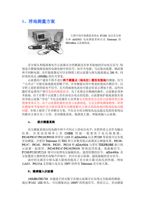
1、浮地测量方案差分探头和隔离器允许示波器安全的测量没有参考接地的浮动电压信号。
特别适合测量线路连接的电源电路中的信号,如开关电源、马达驱动装置、镇流器和不间断电源。
光纤隔离器还可以从物理上把示波器与探头隔离最远200米,同时保持高达100MHz的信号带宽。
示波器用户通常不得不进行两个测量点(地电位)都没有接地的测量。
信号“公共点”可能从接地提高到数千伏,许多测量应用中要求拒绝高共模信号,以分析上面驻留的低电平信号。
无关的接地电流也可能会给显示增加干扰。
这些问题经常迫使用户使用危险的测量技术。
为了实现安全精确的操作,示波器必须参考接地。
由于在整个示波器上存在高电压电击的危险,示波器保护接地系统失效而导致示波器“浮动”不仅会给操作人员带来安全隐患而且还给示波器的变压器绝缘带来压力。
由于示波器机箱的电容与电路相连,它还会降低测量精度。
即使在测量参考接地时也可能仍需要差动测量解决方案以消除接地回路或接地反跳问题。
市场上提供了许多解决方案,不仅安全而且精度高远远超过危险的系统这些解决方案分为三大类:差动测量系统、隔离放大器、和隔离输入示波器。
A、差分测量系统差分测量系统比较电路中两个不同点上的电压电平,并把两者之差作为输出结果。
在更高的频率上其CMRR性能一般要优于电压隔离器。
P6246/P6247/P6248/P6330和带有1103的ADA400A以及P5200等系统可以实现差动测量,并使用Tektronix的TDS和大多数其他示波器显示测量结果。
P6246、P6247、P6248、P6330、P6205、P6210和ADA400A与带有TEKPROBE接口的示波器一起使用。
P6246/P6247/P6248/P6330特别适用快速、低振幅信号。
P5200/P5205/P5210则可以处理电压振幅较高、速度较慢的信号。
ADA400A差分前置放大器即使在高噪声环境中,仍可以显示低频、超低振幅的差分信号。
示波器测220v电网电压
使用示波器对高于安全电压的电路电网进行测量时,要保证探头的测量笔尖和测量参考地电位夹子任何一个接触的部分,都不能对示波器的接地有电位差,探头上的地是参考电位,大地是绝对地电位,但示波器的两个电位是接通的,所以测量时选择的参考地电位不能对大地有电位差,或者说必须是两个不共地电位的。
这样才不会产生电势差,影响测量精度和设备人身的安全。
你只有示波器的电源线不用三线的,就是中间没有地线的那种,或者插头里地线不接,这时示波器就可以直接测开关电源了,不过这种方式应当说是严禁使用的,因为这时,你整个示波器的外壳都会带电了,极其危险,而你现在对此都不懂得里面的关节,发生危险是很有可能的,警告你不能这样做,我只是说出一种可能性,如果你这样操作而发生了危险,后果自负!示波器在测量时,一般都是把地线夹夹在被测电路的地上,这时就让被测电路的地和示波器的地同电位了,示波器的探头再接触被测的点,就可以观测该点的信号波形了,一般我们使用示波器测量时,大多数都是冷地的设备,也就是说,这些设备的地是真正的地电位,或者是浮地,就是说设备的地只是一个参考地,并没有固定的电位,可高可低,而示波器通常是用的市电,为了安全,外壳都是接真正的地的,也就是说外壳是地电位,这样,示波器不采取特殊措施的话,就只能观测真地电位及浮地的信号波形,不是地电位的我们一般就称为热地,这种地和真正的地接在一起,因为电位不一样,你懂的,会产生电流,而市电的内阻通常都是很小的,你想电流会有多大呢?实际上就是短路了,你再想短路了会发生什么情况呢?下面想不想就是你的事了示波器电源插头PE片是接的示波器外壳,示波器探头夹子也是和示波器外壳通的,如果测量220v市电将探头夹子夹住了火线是啥后果!大概明白了,测市电夹子夹住零线探针碰触火线才行。
这么说示波器使用隔离的电源供电也不一定安全,也要考虑其测量的线路板是否有对地电压,为了安全维修电源是否也有必要使用1:1的隔离变压器,将维修的电路板也对地隔离起来通常,隔离说的是操作者人体与电网的隔离。
VP5000A系列说明书(20180109)
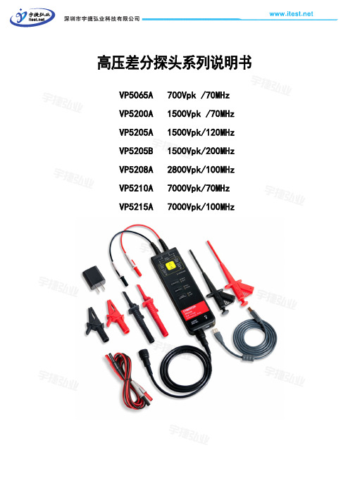
高压差分探头系列说明书VP5065A 700Vpk /70MHzVP5200A 1500Vpk /70MHzVP5205A 1500Vpk/120MHzVP5205B 1500Vpk/200MHzVP5208A 2800Vpk/100MHzVP5210A 7000Vpk/70MHzVP5215A 7000Vpk/100MHz前 言首先,感谢您购买该产品,这份产品使用说明书,是关于该产品的功能、使用方法、操作注意事项等方面的介绍。
使用前,请仔细阅读说明书,正确使用。
阅读完后请好好保存。
说明书中,注释将用以下的符号进行区分。
为安全使用本机器,必须严格遵守以下安全注意事项。
如果不按照该说明书使用的话,有可能会损害机器的保护功能。
此外,违反注意事项进行操作产生的人身安全问题,本公司概不负责。
1、请小心注意触电危险,注意最高输入电压。
2、请勿在潮湿的环境下或者易爆的风险下使用。
3、被测电路接入探头之前,确保先关闭被测电路。
4、测量结束后,先关闭电路,再取走探头。
5、探头BNC输出线连接示波器或者其它设备时,确保BNC 端子可靠接地。
6、使用之前,请检查探头外皮是否有破损,若出现破损情况,请停止使用!7、选择本产品标配的适配器供电。
VP5000A 系列简要说明型号 最大输入差动电压带宽 衰减比 VP5065A 700V 70MHz 10X/100X VP5200A 1500V 70MHz 50X/500X VP5205A 1500V 120MHz 50X/500X VP5205B 1500V 200MHz 50X/500X VP5208A 2800V 100MHz 100X/1000X VP5210A 7000V 70MHz 100X/1000X VP5215A7000V100MHz 100X/1000X该符号表示对人体和机器有危害,必须参照说明书操作。
注意 警告 在错误操作的情况下,用户有受伤的威胁,为避免此类危险,记载了相关的注意事项。
TeKtronix TDS1000C-SC数字存储示波器 说明书
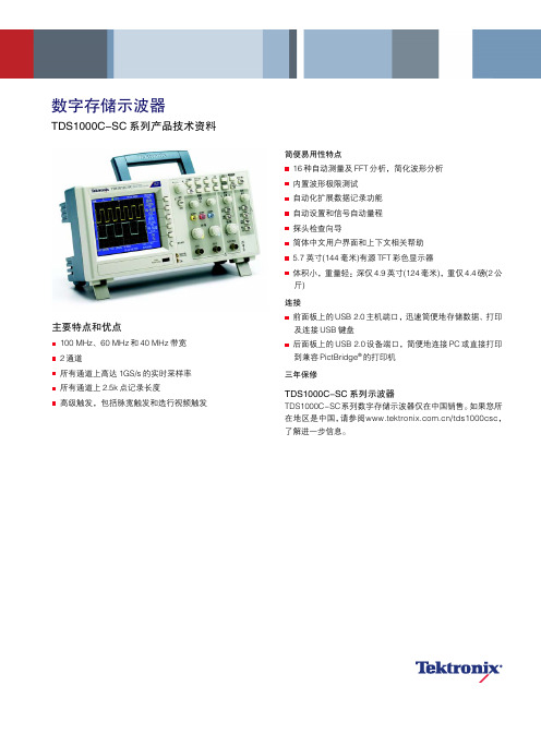
数字存储示波器TDS1000C-SC 系列产品技术资料简便易用性特点16种自动测量及FFT 分析,简化波形分析 内置波形极限测试 自动化扩展数据记录功能 自动设置和信号自动量程 探头检查向导简体中文用户界面和上下文相关帮助 5.7英寸(144毫米)有源TFT 彩色显示器体积小,重量轻:深仅4.9英寸(124毫米),重仅4.4磅(2公斤)连接前面板上的USB 2.0主机端口,迅速简便地存储数据、打印及连接USB 键盘后面板上的USB 2.0设备端口,简便地连接PC 或直接打印到兼容PictBridge ®的打印机三年保修TDS1000C-SC 系列示波器TDS1000C-SC系列数字存储示波器仅在中国销售。
如果您所在地区是中国,请参阅/tds1000csc,了解进一步信息。
主要特点和优点100 MHz、60 MHz 和40 MHz 带宽 2通道所有通道上高达1GS/s 的实时采样率 所有通道上2.5k 点记录长度高级触发,包括脉宽触发和选行视频触发产品技术资料您需要的性能,您可以承受的价格TDS1000C-SC系列数字存储示波器在紧凑的设计中提供了经济的性能。
TDS1000C-SC标配USB连接、16种自动测量、极限测试、数据记录和上下文相关帮助,帮助您在更少的时间内完成更多工作。
杰出的数字精度,实现自动测量高达100 MHz的带宽和1 GS/s的最大采样率,没有任何其它数字存储示波器能够以这种价位提供如此高的性能。
为调试设备提供关键工具高级触发如上升沿/下降沿触发、脉宽触发和视频触发帮助您迅速隔离关心的信号。
一旦捕获了信号,高级数学运算功能和自动测量功能可以加快分析速度。
您可以迅速执行FFT或波形加法、减法或乘法运算。
16种自动测量功能可以迅速可靠地计算重要的信号特点,如频率或上升时间;内置极限测试功能则可以简便地识别信号中的问题。
使用您的母语工作TDS1000C-SC系列是为您这样讲中文的用户设计的。
- 1、下载文档前请自行甄别文档内容的完整性,平台不提供额外的编辑、内容补充、找答案等附加服务。
- 2、"仅部分预览"的文档,不可在线预览部分如存在完整性等问题,可反馈申请退款(可完整预览的文档不适用该条件!)。
- 3、如文档侵犯您的权益,请联系客服反馈,我们会尽快为您处理(人工客服工作时间:9:00-18:30)。
High-voltage Differential ProbesP5200A•P5202A•P5205A•P5210A DataSheetFeatures&Benefits Bandwidths up to100MHzUp to5,600V Differential(DC+pk AC) Up to2,300V Common(RMS)Overrange IndicatorSafety CertifiedSwitchable AttenuationSwitchable Bandwidth Limit ApplicationsFloating MeasurementsSwitching Power Supply DesignMotor Drive DesignElectronic Ballast DesignCRT Display DesignPower Converter Design and ServicePower Device EvaluationThe P5200A can be used with any oscilloscope and enables users to safely make measurements offloating circuits with their oscilloscope grounded.The P5200A Active Differential Probe convertsfloating signals to low-voltage ground-referenced signals that can be displayed safely and easily on any ground-referenced oscilloscope.WARNING:For safe operation,do not use the P5200A High-voltage Differential Probe with oscilloscopes that havefloating inputs(isolated inputs),such as the Tektronix TPS2000Series oscilloscopes.TheP5200A High-voltage Differential Probe requires an oscilloscope or other measurement instrument with grounded inputs.The P5210A is a Differential Probe that is capable of measuringfloating voltages up to5,600V safely and has a bandwidth up to50MHz.It is supplied with two sizes of hook tips and has an overrange visual and audible indicator which warns the user when they are exceeding the linear range of the probe.It can be used with Tektronix TEKPROBE™interface oscilloscopes directly or with any oscilloscope with the use of the1103 TEKPROBE®Power Supply.The P5205A is a100MHz Active Differential Probe capable of measuring fast rise times of signals infloating circuits.This1,300V differential probe can safely measure voltages in IGBT circuits such as motor drives or power converters.It is specifically designed to operate on Tektronix oscilloscopes with TEKPROBE®interface.The P5202A is similar to the P5205A,but this probe has approximately half the attenuation and half the dynamic range of the P5205A and better signal-to-noiseratio.Data SheetCharacteristicsCharacteristic P5200A P5202A P5205A P5210A Attenuation50X/500X20X/200X50X/500X100X/1000XDifferential Input Voltage500X:±1300V50X:±130V 200X:±640V20X:±64V500X:±1300V50X:±130V1000X:±5600V100X:±560VCommon Mode Voltage500X:±1300V50X:±130V 200X:±640V20X:±64V500X:±1300V50X:±130V1000X:±5600V100X:±560VMaximum Rated Input Voltage (each side rated to ground)1000V CAT II450V350V CAT II1000V CAT II2300V1000V CAT IIIBandwidth50MHz100MHz100MHz50MHz Differential Input Impedance10MΩ,2pF5MΩ,2pF10MΩ,2pF40MΩ,2.5pF Input Impedance between eachInput and Ground5MΩ,4pF 2.5MΩ,4pF5MΩ,4pF20MΩ,5pF Cable Length 1.8mTypical CMRR DC:>80dB100kHz:>60dB3.2MHz:>30dB50MHz:>26dBDC:>80dB 100kHz:>60dB 3.2MHz:>40dB 50MHz:>30dBOrdering InformationP5200AActive Differential Probe.Includes:2hook clips,2alligator clips,2pincer clips,2extension cables. Note:Please specify power cord option when ordering.Power Plug Options(P5200A only)Option DescriptionOpt.A0US powerOpt.A1Euro powerOpt.A2UK powerOpt.A3Australian powerOpt.A5Switzerland powerOpt.A6Japanese powerOpt.A10China powerOpt.A11India powerOpt.A12Brazil power P5202AActive Differential Probe.Includes:2hook clips,2alligator clips,2pincer clips,2extension cables.P5205AActive Differential Probe.Includes:2hook clips,2alligator clips,2pincer clips,2extension cables.P5210AActive Differential Probe.Includes:2probe tips,2large hook clips;2small hook clips;2probe heads. Service OptionsOption DescriptionOpt.C3Calibration Service3YearsOpt.C5Calibration Service5YearsOpt.D1Calibration Data ReportOpt.D3Calibration Data Report3Years(with Opt.C3) Opt.D5Calibration Data Report5Years(with Opt.C5) Opt.R3Repair Service3YearsOpt.R5Repair Service5YearsHigh-voltage Differential Probes —P5200A •P5202A •P5205A •P5210A196-3523-00:Extender Leads (1.5m).AC280-FL:HookClips.AC283-FL:PincerClips.AC285-FL:AlligatorClips.020-3070-00:Hook Clip Kit.Probe and Accessory Derating Table (Common Mode,relative to ground,when used with P52xxA Series probes)AccessoryDescriptionP5202A 450V CAT I300V CAT IIP5200A/P5205A 1000V CAT II 600V CAT IIIP5210A 2300V CAT I 1000V CAT III196-3523-002x Extender Leads (1.5m)2300V CAT I 1000V CAT III Standard 450V CAT I 300V CAT II Standard 1000V CAT II 600V CAT III Standard 2300V CAT I 1000V CAT III AC280-FL2x Hook Clips 1000V CAT III 600V CAT IV Standard 450V CAT I 300V CAT II Standard 1000V CAT II 600V CAT III Optional 1000V CAT I 1000V CAT III AC283-FL2x Pincer Clips 1000V CAT III 600V CAT IV Standard 450V CAT I 300V CAT II Standard 1000V CAT II 600V CAT III Optional 1000V CAT I 1000V CAT III AC285-FL2x Alligator Clips 1000V CAT III 600V CAT IV Standard 450V CAT I 300V CAT II Standard 1000V CAT II 600V CAT III Optional 1000V CAT I 1000V CAT III 020-3070-00Hook Clip Kit 2300V CAT I 1000V CAT IIOptional 450V CAT I 300V CAT IIOptional 1000V CAT II 600V CAT IIStandard 2300V CAT I 1000V CAT IIProduct(s)are manufactured in ISO registered facilities. 3Data Sheet Contact Tektronix:ASEAN/Australasia(65)63563900Austria0080022554835*Balkans,Israel,South Africa and other ISE Countries+41526753777Belgium0080022554835*Brazil+55(11)37597627Canada180********Central East Europe and the Baltics+41526753777Central Europe&Greece+41526753777Denmark+4580881401Finland+41526753777France0080022554835*Germany0080022554835*Hong Kong4008205835India0008006501835Italy0080022554835*Japan81(3)67143010Luxembourg+41526753777Mexico,Central/South America&Caribbean52(55)56045090Middle East,Asia,and North Africa+41526753777The Netherlands0080022554835*Norway80016098People’s Republic of China4008205835Poland+41526753777Portugal800812370Republic of Korea00180082552835Russia&CIS+7(495)7484900South Africa+41526753777Spain0080022554835*Sweden0080022554835*Switzerland0080022554835*Taiwan886(2)27229622United Kingdom&Ireland0080022554835*USA180*********European toll-free number.If not accessible,call:+41526753777Updated10February2011For Further Information.Tektronix maintains a comprehensive,constantly expandingcollection of application notes,technical briefs and other resources to help engineers workingon the cutting edge of technology.Please visit Copyright©Tektronix,Inc.All rights reserved.Tektronix products are covered by U.S.and foreign patents,issued and rmation in this publication supersedes that in all previously published material.Specification and price change privileges reserved.TEKTRONIX and TEK are registered trademarks ofTektronix,Inc.All other trade names referenced are the service marks,trademarks,or registered trademarksof their respective companies.05May201151W-11195-4。