高频高压差分探头DP6280
示波器探头和附件(是德科技InfiniiVision 系列)
引言���������������������������������������������������������������������������������������������������������������������������������������������������������������� 2 探头兼容性表������������������������������������������������������������������������������������������������������������������������������������������������� 3 无源探头�������������������������������������������������������������������������������������������������������������������������������������������������������� 5 极限温度无源探头����������������������������������������������������������������������������������������������������������������������������������������� 9 高压无源探头����������������������������������������������������������������������������������������������������������������������������������������������� 10 InfiniiMax 有源探头和附件��������������������������������������������������������������������������������������������������������������������������� 11 InfiniiMode 有源探头和附件������������������������������������������������������������������������������������������������������������������������ 13 通用差分有源探头——DP0001A 高压差分探头������������������������������������������������������������������������������������������ 15 高压差分有源探头��������������������������������������������������������������������������������������������������������������������������������������� 17 单端有源探头����������������������������������������������������������������������������������������������������������������������������������������������� 21 混合信号示波器逻辑探头����������������������������������������������������������������������������������������������������������������������������23 钳形电流探头����������������������������������������������������������������������������������������������������������������������������������������������� 2பைடு நூலகம் N7040A/41A/42A 罗氏线圈交流电流探头��������������������������������������������������������������������������������������������������29 高灵敏度电流探头���������������������������������������������������������������������������������������������������������������������������������������30 楔形探头适配器������������������������������������������������������������������������������������������������������������������������������������������� 32 其他附件� ������������������������������������������������������������������������������������������������������������������������������������������������������33 T2A 探头接口适配器�����������������������������������������������������������������������������������������������������������������������������������35 推荐用于中/低速总线测量的探头���������������������������������������������������������������������������������������������������������������36
GCT-8C钢轨探伤仪高频插座探头自攻丝尼龙线扎、编码器电缆、编码器铸铝小车总成机头提手

GCT-8C钢轨探伤仪高频插座探头自攻丝尼龙线扎、编码器电缆、编码器铸铝小车总成机头提手GCT-8C钢轨探伤仪是一种非破坏性检测仪器,用于检测轨道的质量和损伤情况。
作为关键部件之一,其探头在检测过程中起到了至关重要的作用。
本文将重点介绍GCT-8C钢轨探伤仪的高频插座探头、自攻丝尼龙线扎、编码器电缆、编码器铸铝小车总成机头提手等关键部件的特点和作用。
一、高频插座探头高频插座探头是GCT-8C钢轨探伤仪的核心部件之一,主要用于将探头连接到钢轨上进行信号传输和数据采集。
其优点是信号传输稳定、数据采集精确、使用寿命长等。
同时,高频插座探头的结构复杂,需要具备一定的机械加工能力和装配工艺,因此其成品价格相对较高。
二、自攻丝尼龙线扎自攻丝尼龙线扎是一种用于固定高频插座探头的配件,也是探头与钢轨进行稳定连接的关键部件之一。
其主要优点是牢固可靠、使用寿命长,而缺点则是安装过程相对较复杂、需要涉及到线扎和自攻丝的技术操作。
三、编码器电缆编码器电缆是将探头采集到的信号传输到主机端的重要部件。
其主要特点是传输速率快、传输距离远、信号稳定等优点。
在使用过程中,需要注意电缆的防水性能和抗外力损伤能力,并定期检查电缆是否存在损坏或老化等情况。
四、编码器铸铝小车总成机头提手提手是编码器铸铝小车总成的重要组成部分,主要用于便于操作和控制编码器在钢轨上的位置,并能够适应不同范围的检测需求。
优点是便于操作、可靠性高、使用寿命长等。
其缺点是一次性成本较高,需要根据不同的检测需求来选择不同规格的备件。
总体来说,GCT-8C钢轨探伤仪的关键部件在实际使用过程中需要进行定期检测和维护,以确保其性能和可靠性。
另外,用户在选择备件的时候应该考虑到产品的使用寿命、价格以及适用范围等因素,以便更好地满足各种实际检测需求。
1 SI-9001 25MHz 高压差分探头用户手册说明书

SI-900125MHz HIGH VOLTAGE DIFFERENTIAL PROBEUSER’S MANUALThis probe is in compliance with IEC61010-031 CAT III, Pollution Degree 2.1.Safety Terms and SymbolsTerms appear in this manual:________________________________________________W ARNING. Warning statements identify conditions or practice thatcould result in injury or loss life.________________________________________________CAUTION. Caution statements identify conditions or practice thatcould result in damage to this product or other property.Symbols appear on the product:Danger Protective AttentionHigh V oltage (Earth) Terminal Refer to Manual2.General Safety SummaryReview the following safety precautions to avoid injury and prevent damage to this probe or any products that connected to it.Observe Maximum Working VoltageTo avoid any injury, do not use the probe under the condition that the voltage between either input lead or earth is above 1000Vrms CA T III. This voltage rating applies to both of 1/10 & 1/100 settings.Must be GroundedThis probe is grounded with the shell of BNC connector and an auxiliary grounding terminal, through the grounding conductor of the power cord of the measurement instrument.Before making connections to the input leads of this probe, ensure that the output BNC connector is attached to the BNC connector of the measurement instrument and the auxiliary grounding terminal is connected to a proper ground, while the measurement instrument is properly grounded.Use Fused Test Prods if NecessaryIf this probe is intended to use for measurements in circuits of INSTALLA TION CA TEGORY III, it should incorporate with fused test prods.Do Not Operate Without CoversTo avoid electric shock or fire hazard, do not operate this probe with covers removed.Do Not Operate in Wet/Damp ConditionsTo avoid electric shock, do not operate this probe in wet of damp conditions.Do Not Operate in Explosive AtmosphereTo avoid injury or fire hazard, do not operate this probe in an explosive atmosphere.Avoid Exposed CircuitTo avoid injury, remove jewelry such as rings, watches, and other metallic objects. Do not touch exposed connections and components when power is present.Use Proper Power SourceTo ensure this probe function well, use four AA cells or 6VDC/60mA or regulated 9VDC/40mA mains adaptor or power lead. Do not operate this probe from a power source that applies more than the voltage specified.Do Not Operated With Suspected FailuresIf you suspect there is damage to this probe, have it inspected by qualified service personnel.3.DescriptionBy enabling conventional oscilloscopes to display and measure in-circuit waveforms that are referenced to high common mode voltages. The differential probe extends the measurement capability of oscilloscopes in electronic power converters, inverters, motor speed controls, switch mode power supplies, and many applications.4.Installationa.Simply plug-in the BNC output connector to the vertical input of a general purposedoscilloscope or other measurement instrument, and connects the auxiliary grounding terminal to a proper ground. The measurement instrument must have a ground referenced.b.Connect an appropriate power source to this probe and then turn it on.c.Select the proper attenuation ratio. When measuring signals below 70V, switch the attenuationratio to 1/10 in order to get higher resolution and less noise ratio. Otherwise, set the attenuation ratio to 1/100 when measuring signals up to 700V.W ARNING. To protect against electric shock, use only theaccessories supplied with this probe.ing the appropriate probe accessories, connect the inputs to the circuits undermeasurement.CAUTION. This probe is to carry out differential measurementbetween two points on the circuit under measurement.This probe is not for electrically insulating the circuitunder measurement and the measuring instrument.5. AppearanceThe differential probe looks as follows.a. Output CableThe BNC output connector and an auxiliary grounding terminal are connected to the oscilloscope.b. Input Leads The input leads of the differential probe connect to sprung hooks that come with the probe.c. Sprung Hooks The sprung hooks are connected safely to test points in circuitsunder measurement.6. Power LeadsWe offer the following power leads;a. Lemo ® lead: For the oscilloscope whose power connector is Lemo ® connector.b. USB power cord: For the oscilloscope which offers USB connector.7.SpecificationsBandwidth DC to 25MHz (-3dB) Attenuation Ratio 1:10/100Accuracy ±2%Rise Time Input Impedance 14ns4MΩ//5.5pF each side to groundInput V oltage-Category CA T III-Differential Range ±70V(DC+AC Peak) and 70Vrms @1/10±700V(DC+AC Peak) and 700Vrms @1/100- Common Mode Range±700V(DC+AC Peak) and 700Vrms @1/10 & 1/100 - Absolute Max. V oltage ±1400V(DC+AC Peak) and 1000Vrms @1/10 & 1/100 (Differential or Common Mode)Output V oltage- Swing ±7V (into 50kΩ load)- Offset (typical) <±5mV- Noise (typical) 0.7mVrms- Source Impedance (typical) 50Ω (for using 1MΩ input system oscilloscope) CMRR (typical) -86dB @50Hz, -66dB @20kHZAmbient Operating Temperature -10 to 40℃Ambient Storage Temperature -30 to 70℃Ambient Operating Humidity Up to 85% RHAmbient Storage Humidity Up to 85% RHPower Requirements*- Standard 4xAA cells- Options Power leads, Mains adaptor* (6VDC/60mALength of BNC Cable or regulated 9VDC/40mA), USB power cord 95cmLength of Input Leads 45cmWeight 400gms (probe and PVC jacket)Dimensions (LxWxH) 170mm x 63mm x 21mm* a. The supplied voltage must be less than 12V and greater than 4.4V, otherwise the probe could be damaged or can’t be operated properly.b. polarity is “+” inside and “–” outside. For wrong polarity, built-in circuit protects the probe,no danger or damage will occur.c.When the voltage of the cells become too low, the power indicator on the panel will flicker.8.Derating CurveThe derating curve of the absolute maximum input voltage in common mode is shown asfollows;9.Inspection Procedurea.Connect the BNC output connector to the vertical input of a general purposedoscilloscope.b.To install four AA cells or connect an appropriate mains adaptor or power lead to thecorrect line voltage.c.Set the oscilloscope input coupling to DC and the 1V/div. Center the trace on thedisplay.d.Connect the inputs of the probe to power lines.e.Set the range of the probe to 1/100.f.Then, a 50Hz/60Hz sine-wave of proper amplitude will be displayed on the screen ofthe oscilloscope and this means the probe is working properly.10.CleaningUse a soft cloth to clean the dirt. Prevent damage to probe.a.Avoid immersing the probe.b.Avoid using abrasive cleaners.c.Avoid using chemicals contains benzene or similar solvents.Lemo® is the registered trademarksDate: May 16, 2019。
T6290综测仪产品介绍

T6290
标准差(整体)/(组内) 0.44/0.66 0.18/0.22 0.25/0.64 0.15/0.35 0.11/0.34 0.13/0.19 0.13/0.17 0.11/0.25 0.22/0.43 0.47/0.72 0.36/0.36 0.33/0.51 0.12/0.25 0.50/0.72 0.21/0.26
北京公司: 朝阳区中化地质大厦一层 研发中心
上海总部: 松江区新飞路1500号26栋 生产制造、质量控制
深圳公司: 南山区桃源街道田寮大厦1208 销售、技术支持、仓储、物流
产业经历
T6290申请10项发明专利保护
2014重组成立为准电子,推出T6290产线型综测 仪,并实现规模量产应用 2014年国家重大专项全模综测仪项目 2013年实现LTE/TD/W/GGE多模综测仪产线规模应用 2012年TDD/FDD-LTE综测仪平台发布, TDD/FDD LTE Advanced功能开发 2011年T6280多模信令综测仪发布 2010年LTE/WCDMA/GGE开发。 2009年综测仪在TD生产线规模应用(300台)
• 工厂采购在仪表高峰期从多家仪表租赁商租用仪表,不同厂家CMW500的版本,精
解决工厂租用仪表 的品质保障及一站 式获得解决方案
准度,软件盗版问题,仪表年度校准维护参差不齐,无法管理。 •各租赁厂商提供的测试配件品质堪忧 •T6290租赁仪表每半年原厂检查和校准一次,出库前使用高级源测试指标,保障仪表 的精准性,仪表品质,可用数量,技术支持能力,极大解决由于采购鱼目混杂的租赁 源头的仪表品质不确定和混乱,引发的生产可靠性保障问题
• 与德与振华工厂战略合作,4G项目全线采用T6290生产,在振华长期保持100台左右 的使用量,为魅族,中兴,宇龙,HTC项目做生产,客户反馈良好,得到各界高度 信任。 • ONTIM与中诺工厂ODM华为的项目全线采用T6290生产,中诺及其外协厂(光弘, 德邦)长期保持100台左右的使用量,性能稳定。生产的华为“畅享5”项目获中国 移动2015年千元智能机项目质量第一名。 • 华勤给华为的ODM项目在长城开发虎门新厂的项目自2015年底导入T6290以来,受 到客户的一致好评,目前T6290在该厂保持60台左右的使用量,并不断增加。 • 德赛4G产线指定使用T6290仪表,为TCL/ACTEL,天珑等生产,随着4G产品比重加大, 目前已经增加至30台以上。
主要技术性能指标或规格要求

型号 高压差分 隔离探头 THDP0200 高压差分 隔离探头 THDP0100
主要技术(性能)指标或规格要求
衰减倍数:50/500X; 输入电压:500X:±1500V; 最大对地输入电压:1000V CAT II
带宽:200MHz; 输入阻抗:10MΩ¶<2pF
衰减倍数:100/1000X; 输入电压:1000X:±6000V; 最大对地输入电压:2300V CAT I
别
数量
泰克
2
泰克
2
备注
1、因项目急用,要求交付周期短; 2、需交付全新正品,不得提供翻修件、长期库 存件,供方需有泰克官方授权,提供原厂售后 服务承诺书;
1、因项目急用,要求交付周期短; 2、需交付全新正品,不得提供翻修件、长期库 存件,供方需有泰克官方授权,提供原厂售后 服务承诺书;
高压差分探头P5200系列用户说明书

Features & BenefitsBandwidths Up to 100MHz Up to 5,600V Differential (DC + pk AC)Up to 2,200V Common (RMS) Overrange Indicator Safety Certified Switchable Attenuation Switchable Bandwidth LimitApplicationsFloating Measurements Switching Power Supply Design Motor Drive Design Electronic Ballast Design CRT Display Design Power Converter Design and ServicePower Device EvaluationHigh Voltage Differential ProbesP5200 • P5205 • P5210The P5200 can be used with any oscillo-scope and enables users to safely make measurements of floating circuits with their oscilloscope grounded. The P5200 Active Differential Probe converts floating signals to low-voltage ground referenced signals that can be displayed safely and easily on any ground referenced oscilloscope. WARNING:For safe operation, do not use the P5200 High Voltage Differential Probe with oscilloscopes that have floating inputs (isolated inputs), such as the T ektronix TPS2000 Series oscilloscopes andTHS700 Series oscilloscopes. The P5200High Voltage Differential Probe requiresan oscilloscope or other measurement instrument with grounded inputs.The P5210 is a Differential Probe that is capable of measuring floating voltages up to 5,600V (DC +pk AC) safely and has a bandwidth up to 50MHz. It is supplied with two sizes of hook tips and has anP5205.P5200.P5210.1981High Voltage Differential ProbesP5200 •P5205 •P52102overrange visual and audible indicatorwhich warns the user when they areexceeding the linear range of the probe. Itcan be used with T ektronix TEKPROBE™interface oscilloscopes directly or with anyoscilloscope with the use of the 1103TEKPROBE®Power Supply.The P5205 is a 100MHz Active DifferentialProbe capable of measuring fast rise timesof signals in floating circuits. This 1,300Vdifferential probe can measure safelyvoltages in IGBT circuits such as motordrives or power converters. It is specificallydesigned to operate on T ektronix oscillo-scopes with TEKPROBE interface.*1The RMS value of the waveform shall not exceed the Common Mode Voltage (RMS) for either lead.*2TDS7154B, TDS7254B, TDS7404B, TDS6404, TDS6604, CSA7154, and CSA7404B require a TCA-1MEG Buffer Amplifier.*3WARNING:For safe operation, do not use the P5200 High Voltage Differential Probe with oscilloscopes that have floating inputs (isolated inputs), such as the Tektronix TPS2000 series oscilloscopesand THS700 series oscilloscopes. The P5200 High Voltage Differential Probe requires an oscilloscope or other measurement instrument with grounded inputs.High Voltage Differential ProbesP5200 •P5205 •P5210High Voltage Differential Probes • /accessories 3P5200.P5205.P5210.。
腾达微电子TDP系列差分活动探头说明书
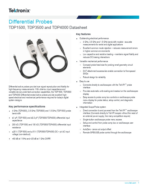
Differential ProbesTDP1500, TDP3500 and TDP4000 DatasheetDifferential active probes provide truer signal reproduction and fidelity for high-frequency measurements. With ultra-low input capacitance andversatile device-under-test connection capabilities, the TDP1500, TDP3500and TDP4000 Differential-ended Active probes provide excellent high-speed electrical and mechanical performance required for today's digital system designs.Key performance specifications4 GHz (TDP4000), 3.5 GHz (TDP3500) and 1.5 GHz (TDP1500) probebandwidth≤1 pF (TDP1500) and ≤0.3 pF (TDP3500/TDP4000) differential inputcapacitance200 kΩ (TDP1500) and 100 kΩ (TDP3500/TDP4000) differential inputresistance±25 V (TDP1500) and ±15 V (TDP3500/TDP4000) DC + pk AC inputvoltage (non-destruct)>60 dB at 1 MHz and >25 dB at 1 GHz CMRRKey featuresOutstanding electrical performance4 GHz, 3.5 GHz and 1.5 GHz bandwidth models - accuratemeasurements for serial and digital applicationsExcellent common mode rejection – reduces measurement errorsin higher common environmentsLow capacitive and resistive loading – maintains signal fidelity andreduces DC biasing interactionsVersatile mechanical performanceCompact probe head size for probing small geometry circuitelementsDUT attachment accessories enable connection to fine-spacedSMDsRobust design for reliabilityEasy to useConnects directly to oscilloscopes with the TekVPI ™ probeinterfaceProvides automatic units scaling and readout on the oscilloscopesdisplayEasy access to probe comp box controls or oscilloscope probe menu display for probe status, setup control, and diagnosticinformationIntegrated Scope/Probe systemDirect connection to and powered from the TekVPI ™ oscilloscope interface (Connects directly to TekVPI scopes without the need ofan external power supply, like many competitors require)Single-button oscilloscope probe menu accessSetup and control from probe comp box or oscilloscope userinterfaceAutoZero - zeros out output offsetRemote GPIB/USB probe control through the oscilloscopeApplicationsDesign, validation, debugging, and characterization of common high-speed serial bus designs:I 2CCAN/LINSPISerial ATAEthernet (GbE)USB 2.0FIreWire (1394b)Signal integrity, jitter, and timing analysisManufacturing, engineering, and testA better measurement toolSpecifically designed for use and direct connection to oscilloscopes with the TekVPI ™ probe interface, the TDP1500, TDP3500 and TDP4000Differential probes achieve high-speed signal acquisition and measurementfidelity by solving three traditional problems:DUT loading effects - Are reduced by lower input capacitance and highinput resistanceDUT connectivity - A variety of accessories exist for attaching to smallSMDs, some come standard or recommendedMaximizing of system (oscilloscope and probe) bandwidth - Probing solutions for all measurements for TekVPI interface oscilloscope models up to 4 GHzFor the best probe support, download and install the latest version of the oscilloscope software from /software/downloads .DatasheetTDP1500, TDP3500 and TDP4000 Differential probesSpecificationsAll specifications are guaranteed unless noted otherwise. All specifications apply to all models unless noted otherwise.Warranted characteristicsBandwidth (probe only)TDP1500≥1.5 GHz warrantedRise time (probe only)TDP3500≤140 psAttenuationTDP15001X, 10XTDP35005XCMRR>60 dB at 1 MHz, >25 dB at 1 GHzMaximum input voltage(nondestruct)TDP1500±25 V (DC + pk AC)TDP3500±15 V (DC + pk AC)TDP4000±15 V (DC + pk AC)Typical characteristicsBandwidth (probe only)TDP3500≥3.5 GHzTDP4000≥4 GHzRise time (probe only)TDP1500≤265 psTDP4000≤125 psDifferential input capacitanceTDP1500≤1 pFTDP3500≤0.3 pFTDP4000≤0.3 pFDifferential input resistanceTDP1500200 kΩTDP3500100 kΩTDP4000100 kΩNoise levelTDP1500<≈≈Propagation delay 5.4 nsCommon mode input rangeTDP1500±7 V (1X)±7 V (10X)TDP3500+5 V to -4 V TDP4000+5 V to -4 V Input offset rangeTDP1500±7 V (10X or 1X)TDP3500±1 V displayed TDP4000±1 V displayed Differential input dynamic rangeTDP1500±8.5 V (10X)±850 mV (1X)TDP3500±2 V TDP4000±2 VNominal characteristicsRecommended oscilloscope interfaceTekVPI ™ ProbePower requirementsPower requirementsPowered directly by oscilloscopes with the TekVPI probe interface.Physical characteristicsDimensionsWeight1Typical for TDP1500.2Typical for TDP1500.DatasheetTypical characteristicsTDP1500, TDP3500 and TDP4000 Differential probes Ordering informationModelsTDP1500 1.5 GHz Differential Probe with TekVPI™ Probe Interface, Certificate of Traceable Calibration Standard.TDP3500 3.5 GHz Differential Probe with TekVPI™ Probe Interface, Certificate of Traceable Calibration Standard.TDP4000 4 GHz Differential Probe with TekVPI™ Probe Interface, Certificate of Traceable Calibration Standard.OptionsLanguage optionsOpt. L0English manualOpt. L5Japanese manualOpt. L7Simplified Chinese manualService optionsOpt. C3Calibration Service 3 YearsOpt. C5Calibration Service 5 YearsOpt. D1Calibration Data ReportOpt. D3Calibration Data Report 3 Years (with Opt. C3)Opt. D5Calibration Data Report 5 Years (with Opt. C5)Opt. R3Repair Service 3 Years (including warranty)Opt. R5Repair Service 5 Years (including warranty)Opt. SILV900Standard warranty extended to 5 yearsAccessoriesTDP1500 standard accessoriesDatasheetTDP3500 and TDP4000 standard accessoriesRecommended accessoriesTektronix is registered to ISO 9001 and ISO 14001 by SRI Quality System Registrar.Product(s) complies with IEEE Standard 488.1-1987, RS-232-C, and with Tektronix Standard Codes and Formats.TDP1500, TDP3500 and TDP4000 Differential probesDatasheetASEAN / Australasia (65) 6356 3900 Austria 00800 2255 4835*Balkans, Israel, South Africa and other ISE Countries +41 52 675 3777 Belgium 00800 2255 4835*Brazil +55 (11) 3759 7627 Canada180****9200Central East Europe and the Baltics +41 52 675 3777 Central Europe & Greece +41 52 675 3777 Denmark +45 80 88 1401Finland +41 52 675 3777 France 00800 2255 4835*Germany 00800 2255 4835*Hong Kong 400 820 5835 India 000 800 650 1835 Italy 00800 2255 4835*Japan 81 (3) 6714 3086 Luxembourg +41 52 675 3777 Mexico, Central/South America & Caribbean 52 (55) 56 04 50 90Middle East, Asia, and North Africa +41 52 675 3777 The Netherlands 00800 2255 4835*Norway 800 16098People's Republic of China 400 820 5835 Poland +41 52 675 3777 Portugal 80 08 12370Republic of Korea +822 6917 5084, 822 6917 5080 Russia & CIS +7 (495) 6647564 South Africa +41 52 675 3777Spain 00800 2255 4835*Sweden 00800 2255 4835*Switzerland 00800 2255 4835*Taiwan 886 (2) 2656 6688 United Kingdom & Ireland 00800 2255 4835*USA180****9200* European toll-free number. If not accessible, call: +41 52 675 3777For Further Information. Tektronix maintains a comprehensive, constantly expanding collection of application notes, technical briefs and other resources to help engineers working on the cutting edge of technology. Please visit . Copyright © Tektronix, Inc. All rights reserved. Tektronix products are covered by U.S. and foreign patents, issued and pending. Information in this publication supersedes that in all previously published material. Specification andprice change privileges reserved. TEKTRONIX and TEK are registered trademarks of Tektronix, Inc. All other trade names referenced are the service marks, trademarks, or registered trademarks of their respective companies.16 Jul 2018 51W-20565-8 。
SIGLENT鼎阳科技探头产品手册

SIGLENT数字存储示波器无源探头隔离通道模块实现示波器通道隔离原理图STB板该测试系统主要功能为输出各种信号以辅助演示示波器的各种功能,STB板可以输出的信号包括有方波、正弦波、随机码、脉冲、BURST、快沿信号以及调幅信号等10种典型信号。
STB板系统测试图50MHz带宽1000X衰减最大输入电压15KV AC/DC电流测量测量范围5mA至100A切换比率100mV/A,10mV/A40MHz带宽最大测试电流30Arms峰值电流50A(<10ns)25MHz带宽10X、100X衰减最大差动电压输入700V带宽最大差动电压输入6500V200X、500X、1000X衰减100MHz带宽最大差动电压输入6500V、200X、500X、1000X衰减高压差分探头 DPB530 USB-GPIB 适配器SDS1000系列数字示波器便携包30MHz带宽50X、500X衰减最大差动电压输入1300V USB-GPIB适配器兼容SDS1000示波器 SDS1000数字示波器便携包1.特点与特性3.应用■ EMI 辐射干扰源定位 ■磁场强度检测SRF503 是一款主要用于查找干扰源,判定 干扰产生原因的高性价比近场探头。
可用来检测器件表面的磁场方向以及强度; 检测磁场耦合的通道,从而调整连接器位置;检 测模块附近的磁场环境。
为了降低干扰,寻找到 真正的干扰源或者是其传播的途径是非常有必要 的,通过近场探头测量可以很方便地实现定位功 能。
通过配合前置放大器可以提高系统测试灵敏 度。
大大的减少产品的研发周期,减少往返实验 室的时间和金钱,减少不必要的错误测试。
SRF503近场探头就是解决问题的最好利器!近场探头规格型号特性SRF503-1SRF503-2SRF503-3SRF503-44.各部分名称SRF503-1SRF503-2SRF503-3SRF503-4配套输出线:约1.2m探头SMB 接口探头SMB 接口SMB 接口SMB 接口探头探头BNC 输出接口连接探头SMB 接口6.装箱单。
- 1、下载文档前请自行甄别文档内容的完整性,平台不提供额外的编辑、内容补充、找答案等附加服务。
- 2、"仅部分预览"的文档,不可在线预览部分如存在完整性等问题,可反馈申请退款(可完整预览的文档不适用该条件!)。
- 3、如文档侵犯您的权益,请联系客服反馈,我们会尽快为您处理(人工客服工作时间:9:00-18:30)。
第6页
■ 附件说明
深圳市优测科技有限公司
鳄鱼夹(CK-261 红黑 1 对)
鳄鱼夹(CK-262 红黑 1 对)
活塞探夹 (CK-281 红黑 1 对)
测试勾(CK-284 红黑一对)
输入延长线(CK-301 红黑 1 对) 同轴电缆输出线(CK-310)
图一 BNC 公头转双母头
图二 BNC 公头转双接线柱
图三 BNC 母头转双接线柱
图四 BNC 公头转 50 欧姆负载
第 12 页
深圳市优测科技有限公司
11.1 安装
接电源适配器到电压探头,电压探头绿色指示灯亮,为保证精度,开机 20 分后 测试探头指标。 拧掉 BNC 公头转双接线柱的红黑塑胶盖。
二、DP6000 系列简要说明
型号
DP6070 DP6150 DP6150A DP6150B DP6280 DP6700 DP6700A
最大输入差动电 压
700V 1500V 1500V 1500V 2800V 7000V 7000V
带宽
70MHz 70MHz 100MHz 200MHz 100MHz 70MHz 100MHz
USB 线(CK-315 AM-BM,1.5 米)
电源适配器(CK-605) USB 5V/1A
第7页
五、技术规格
型号
带宽(-3dB)
上升时间
精度
量程选择(衰减比)
最大差分测量电压 (DC + Peak AC)
共模电压(DC + Peak AC)
最大差模电压 VS 频率曲 线
最大输入对地电压 (Vrms)
输入阻抗
单端对地 两输入端
输入电容
单端对地 两输入端
DC
CMRR
100kHz
1MHz
噪声(Vrms)
过载指示电压阀值
延时 时间
探头主机 BNC 线(1m)
带宽限制(5MHz)
过载指示灯(红灯)
过载报警声
自动保存功能
偏置可调功能
终端负载要求
电源
安全符合标准
EMC 符合标准
11.2 DC 精度
探头输出端接 BNC 母头转双接线柱,数字万用表的两个输入端插入接线柱孔。
探头输入端连接绝缘活塞电夹,然后连接校正仪的输出端且信号发生器输出关闭,红色电夹接正极,
黑色电夹接负极。
探头的衰减倍数设置在第一个档位。
参照下表,设置信号源的输出值。
使能信号的输出,观察并记录该档位的输出电压。
深圳市优测科技有限公司
一、概述
DP6280 高压差分探头是针对高压差分信号的测量,满足浮地测量的需求。 其带宽最高达到 200MHz,满足了大部分测试系统的需要; 丰富的量程可供选择,其差动测量电压范围满足大部分测试电路的要求; 用户可进入测试模式,调整偏置电压,探头长期使用后若出现失调现象,用户可进入该模式,调整偏 置,实现归零; 电子轻触式按键,使得使用寿命更长; 具有 5MHz 带宽限制功能选择,5MHz 频率带宽满足大部分开关电源中 FETs 的开关频率的测量,并可 以滤除更高频率的噪声和干扰; 带有声光报警功能,且可手动关闭声音报警功能,更具有人性化设计; USB 供电接口,使用更加方便灵活; 探头配备标准的 BNC 输出接口,可与任何厂家的示波器配合使用(要求示波器的输入阻抗设置为 1M Ω;当选择 50Ω时,衰减倍数会多衰减一倍),测量被测电路波形; 自动保存功能,防止掉电后用户重复操作。 探头具备良好的共模噪声抑制能力,输入端具有较高的输入阻抗和较低电容,可以准确高速地测量差 分电压信号。 可广泛用于开关电源﹑变频器﹑电子镇流器﹑变频家电和其它电气功率装置等的研发﹑调试或检修工 作中。
第9页
深圳市优测科技有限公司
八、操作步骤
测试前应估计被测电压幅值,若超过电压量程,可能会损坏探头,造成产品损坏。 输入线和输出线连接好探头;探头与示波器或者其它测量仪器连接。 电源适配器接入电压探头,绿色电源指示灯亮。根据测量电压,探头选择合适的量程;当测量电压超 过量程时,过载指示灯会亮,且有报警声,报警声也可以手动选择关闭。 根据探头的量程设置好示波器或者其它测量仪器的衰减比例;根据被测电压的大小,调整好示波器的 灵敏度。 根据需要连接探头夹具,连接被测对象开始测量。测试时,探头主体应尽量远离高压脉冲电路以减小 对探头的干扰。 测试完毕后,先关闭被测电路电源,再关闭探头电源,将两个输入端与被测点断开,输出 BNC 插头从 示波器上拔下。
产品标配附件说明:
型号
鳄鱼夹(CK-261) 活塞探夹 (CK-281) 测试勾(CK-284) 输入延长线(CK-301) 同轴电缆输出线(CK-310) USB 线(CK-315) 电源适配器(CK-605)
DP6280 CATIII 1000V CATIV 600V CATIII 1000V CATII 1000V CATIII 1000V 双端 BNC 接口同轴线 长度 1m AM-BM,1.5 米
衰减比
10X/100X 50X/500X 50X/500X 50X/500X 100X/1000X 100X/1000X 100X/1000X
第2页
三、产品实物图
深圳市优测科技有限公司
第3页
深圳市优测科技有限公司
第4页
调整好后,按下
按键,切换到低衰减倍数档位偏置调整,按下
按键,偏置递增;
按下
按键;偏置递减。
调整好后,按下
按键,退出测试模式,偏置调整结束,过载指示灯灭,进入正常工作模式。
第 10 页
深圳市优测科技有限公司
十、使用注意事项:
Note 在测量时应尽量使输入线缠绕,这样可以更好的消除引线电感和外界噪声,提高高频响应和抗干扰的 能力。缠绕方式如下图所示:
深圳市优测科技有限公司
高频高压差分探头 DP6280
DP6000 系列高压差分探头是针对高压差分信号的测量,满足浮地测量的需求。包括的型 号有 DP6070、DP6150、DP6150A、DP6150B、DP6280、DP6700、DP6700A。
第1页
关闭信号源的输出。
探头的衰减倍数切换到第二个档位。
重复步骤 4~6,计算结果是否在精度范围内。
型号
衰减比例 信号源输出电压
探头期望输出电压
探头实际 输出电压
DP6280
100X 1000X
10V 100V
100mV±2mV 100mV±2mV
11.3 上升时间
BNC 公头转双母头(如图一所示),一端接 50 欧姆负载,一端接图二所示的 BNC 公头转双接线柱。公头接标准信号发生器且信号发生器输出关闭。 探头的输出端接示波,衰减倍数设置在第一个档位。 设置标准信号发生器参数,参考下表。 使能信号源输出,并记录上升时间值。 关闭信号源输出。 探头的衰减倍数切换到第二个档位。 重复步骤 3~5,计算是否在范围内。
下面的测试步骤是为了验证产品的电气特性,测试设备要求如下:
深圳市优测科技有限公司
设备
示波器
标准信号发 生器;
校正仪
数字万用表 绝缘活塞电 夹 BNC 转接头 1 BNC 转接头 2
BNC 转接头 3 负载终端
最低要求 带宽≥100MHZ;精度≦1.5%如:泰克 MSO/DSO4000
幅值精度≤0.75%;上升时间≤3ns 如:FLUKE/WAVETEK 9100
七、环境特性
型号 工作温度 存储温度 工作湿度 存储湿度 工作海拔高度 存储海拔高度
参数 28cm 1m 1m 85*40*17mm 106*43*16mm 152*50*13mm 121*23*23mm 195*65*28mm 216g
参数 0℃~50℃ -30℃~70℃
≤85%RH ≤90%RH 3000m 12000m
型号 衰减比例 信号源电压,频率设置 探头期望上升时间 探头实际上升时间
DP6280
100X 1000X
20Vp-p 100MHz 20Vp-p 100MHz
≤3.5ns ≤3.5ns
第 13 页
深圳市优测科技有限公司
11.4 DC 共模抑制比(CMRR) DP6000 系列探头分别设置在低衰减比例档位(10X,50X,100X)。 信号源设置 500V 直流电压,此时电压输出关闭。 探头的两个输入端接 500V 电压。 探头输出接 BNC 母头转双接线柱(如图三所示),插入数字万用表的两个输入端。 使能信号源输出,分别记录电压输出值,核对下表,计算是否在范围内。 测试结束后关闭校正仪。
在测量时应尽量不要延长输入线,否则会引入更多的噪声。如果必须要额外加长输 入线,则应保证延长线的长度相同,而且输入频率不超过 5MHz,如果超过 5MHz 输出 会有一定的误差。如下图所示:
未添加输入延长线的波形
添加输入延长线(CK-301)的波形
第 11 页
十一、性能验证
九、测试模式(偏置设置)
用户可以进入测试模式,根据需要调整偏置,探头使用年限久后,可能产生失调问题,开机后不在零 位,调整方法如下:
按住
这两个按键,输入端口短路。
插上电源开机,开机后会进入测试模式,过载指示灯会亮,松开两个按键。
该状态下进入高衰减倍数偏置调整,按下 减。
按键,偏置递增;按下Βιβλιοθήκη 按键;偏置递四、产品及附件说明
■ 探头主体说明 以 DP6280 为例,不同产品,电压﹑量程﹑带宽会有所不同
深圳市优测科技有限公司
第5页
深圳市优测科技有限公司
详细说明: ① 输入接口:标准的红黑插座。红为正,黑为负,当接反后,输出会反相;配合标配的红 黑输入线使用。 ② 档位(ATTENUATION):不同档位代表不同量程范围,例如 DP6150A:500X 表示最高测 量电压为 1500V;50X 表示最高测量电压为 150V;DP6700:1000X 表示最高测量电压为 7000V;100X 表示最高测量电压为 700V;示波器衰减倍数应该根据探头的档位选择做相 应设置。 ③ 带宽(BANDWIDTH):该系列产品具有带宽选择功能,默认为产品的满带宽(FULL) 当测量低频信号,防止高频信号的干扰,可选择 5MHz 带宽限制功能。 ④ 过载报警功能(AUDIBLE OVERRANGE):测量范围超过量程时,会发生声光报警,该功 能控制是否打开蜂鸣器报警功能,ON 为打开声音报警;OFF 为关闭声音报警。 ⑤ 输出接口:标配标准的 BNC 输出接口,可接任何厂家示波器,要求示波器输入阻抗设置 为 1MΩ;如设置成 50Ω,会造成输出值衰减为实际值的一半。 ⑥ 电源接口:标准的 USB B 型接口,通过标配的 USB 适配器供电;也可以通过示波器供电, 使用方便;也可以通过 USB 移动电源供电,方便野外测试。 ⑦ 出厂设置:出厂设置默认为高衰减倍数档位、选择 FULL 带宽、打开声音报警功能。产 品具有自动记忆功能,自动保存关机前状态。