DJFK6型角阀控制器说明书
各种阀门说明书
通径 (mm)
25~150
25~200
工作压力 (MPa)
0.6
1.0
试验压力
密封
强度
0.66
0.9
1.1
1.5
试验温度
常温 常温
Ⅱ.作用原理和结构特点
3. 本阀有阀体、阀盖、阀杆、阀办、隔膜和驱动零件等组成。基本结构见图 1 4. 阀门的启闭是靠旋转手轮而达到的。当顺时针旋转手轮时,阀办下降使通路截断;反之阀
四、工作原理 手动阀门用手转动手轮,使阀杆上升、下降,从而带动闸板上、下运动,开启、关闭阀
门。顺时针方向旋转,闸板下降,阀门关闭。逆时针方向旋转,闸板上升,阀门开启。
五、保管、保养、安装和使用 5.1 阀门应存放在干燥,通风的室内,阀门通道两端应堵塞。 5.2 长期存放的阀门应定期检查,清除污物。应特别注意密封面的清洁,防密封面的损坏。 5.3 安装前应仔细核对阀门标志是否与使用要求相符。 5.4 安装前应检查阀门内腔和密封面,如有污垢,应使用清洁布擦拭干净。
止回阀说明书
1.范围
本 说 明 书 包 括 了 公 称 通 径 DN15mm~600mm(1/2”~24”) 、 公 称 压 力 PN1.6MPa~16MPa(ANSI CLASS150~900)螺纹端、法兰端、对焊端和承插焊端连接的旋启式、 升降式止回阀。
2.用途
2.1 本阀用于管道或装置中,防止介质倒流。 2.2 根据介质选用阀门的材质。 2.2.1 碳钢阀门适用于水、蒸汽、油品等介质。 2.2.2 不锈钢阀门适用于腐蚀性介质。 2.3 适用温度:
1.更换阀座 2.更换蝶板
驱动机构失效
1.连接键损坏脱落 2.锥销剪断
1.更换键 2.更换锥销
PFC-6控制器使用说明书
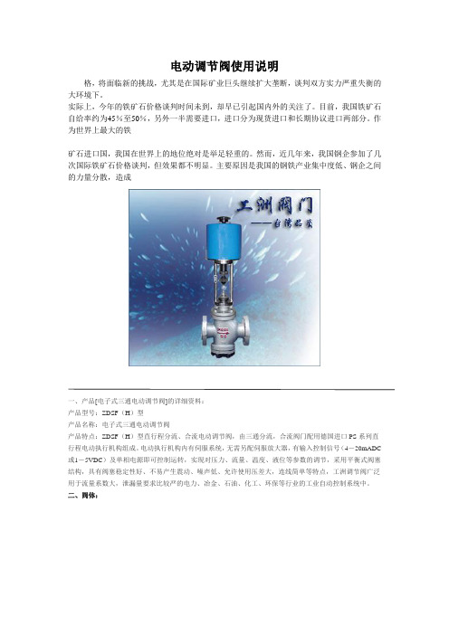
电动调节阀使用说明
电动调节阀使用说明格,将面临新的挑战,尤其是在国际矿业巨头继续扩大垄断,谈判双方实力严重失衡的大环境下。
实际上,今年的铁矿石价格谈判时间未到,却早已引起国内外的关注了。
目前,我国铁矿石自给率约为45%至50%,另外一半需要进口,进口分为现货进口和长期协议进口两部分。
作为世界上最大的铁矿石进口国,我国在世界上的地位绝对是举足轻重的。
然而,近几年来,我国钢企参加了几次国际铁矿石价格谈判,但效果都不明显。
主要原因是我国的钢铁产业集中度低、钢企之间的力量分散,造成一、产品[电子式三通电动调节阀]的详细资料:产品型号:ZDSF(H)型产品名称:电子式三通电动调节阀产品特点:ZDSF(H)型直行程分流、合流电动调节阀,由三通分流,合流阀门配用德国进口PS系列直行程电动执行机构组成。
电动执行机构内有伺服系统,无需另配伺服放大器,有输入控制信号(4-20mADC 或1-5VDC)及单相电源即可控制运转,实现对压力、流量、温度、液位等参数的调节,采用平衡式阀塞结构,具有阀塞稳定性好、不易产生震动、噪声低、允许使用压差大,连线简单等特点,工洲调节阀广泛用于流量系数大,泄漏量要求比较严的电力、冶金、石油、化工、环保等行业的工业自动控制系统中。
二、阀体:形式:三通双座铸造阀公称通径:25-300mm公称压力:PM1.6 4.0 6.4MPa连接形式:法兰式按JB78-59 JB79-59材料:HT200 ZG230—450 ZG1Cr18Ni9TiZG0Cr18Ni12Mo2Ti三、上阀盖:常温型:-20℃-+200℃散热型:-40℃-+450℃压盖形式:螺栓压紧式填料:V型聚四氟乙烯填料、柔性石墨、不锈钢波纹管四、阀内组件:阀芯形式:双导向双座套筒型阀芯流量特性:等百分比特性,线性特性和快开特性材料:1Cr18Ni9Ti 0Cr18Ni12Mo2Ti五、执行机构:类型:可选PS、3810、ZAZ型(DN100以内)、DKZ型(DN100以上)系列电子式直行程执行机构。
贝利摩6路控制阀技术数据表说明书
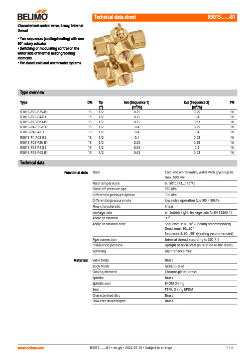
R3015-..-..-B1Characterised control valve, 6-way, Internalthread• Two sequences (cooling/heating) with one 90° rotary actuator• Switching or modulating control on the water side of thermal heating/cooling elements• For closed cold and warm water systemsType overviewTypeDN Rp ["]kvs (Sequence 1)[m³/h]kvs (Sequence 2)[m³/h]PN R3015-P25-P25-B1151/20.250.2516R3015-P25-P4-B1151/20.250.416R3015-P25-P63-B1151/20.250.6316R3015-P4-P25-B1151/20.40.2516R3015-P4-P4-B1151/20.40.416R3015-P4-P63-B1151/20.40.6316R3015-P63-P25-B1151/20.630.2516R3015-P63-P4-B1151/20.630.416R3015-P63-P63-B1151/20.630.6316Technical dataFunctional dataFluidCold and warm water, water with glycol up to max. 50% vol.Fluid temperature 6...80°C [43...176°F]Close-off pressure ∆ps 350 kPa Differential pressure Δpmax 100 kPaDifferential pressure note low-noise operation Δpv100 < 50kPa Flow characteristic linearLeakage rate air-bubble tight, leakage rate A (EN 12266-1)Angle of rotation 90°Angle of rotation noteSequence 1: 0...30° (Cooling recommended)Dead zone: 30...60°Sequence 2: 60...90° (Heating recommended)Pipe connection Internal thread according to ISO 7-1Installation position upright to horizontal (in relation to the stem)Servicingmaintenance-free MaterialsValve body Brass Body finish nickel-plated Closing element Chrome-plated brass Spindle Brass Spindle seal EPDM O-ring SeatPTFE, O-ring EPDM Characterised disc Brass Flow rate diaphragmsBrassR3015-..-..-B1•••••Mode of operationPressure compensationRecommended installation positionsWater quality requirements Safety notesThe valve has been designed for use in stationary heating, ventilation and air-conditioning systems and must not be used outside the specified field of application, especially in aircraft or in any other airborne means of transport.Only authorised specialists may carry out installation. All applicable legal or institutional installation regulations must be complied during installation.The valve does not contain any parts that can be replaced or repaired by the user.The valve may not be disposed of as household refuse. All locally valid regulations and requirements must be observed.When determining the flow rate characteristic of controlled devices, the recognised directives must be observed.Product featuresThe 6-way characterised control valve is adjusted by a rotary actuator. The actuator is connected by a modulating control system or a bus signal and moves the ball of the ball valve to the position dictated by the control signal.If the valve is adjusted in the clockwise direction (till the end stop), e.g. the cooling sequence is completely enabled; if the valve is adjusted in the counter-clockwise direction (90°), e.g. the heating sequence is completely enabled.In cases of combined heating/cooling control elements, the fluid remains in the control element when in the closed position (no heating or cooling). The pressure of the enclosed fluid can rise or fall due to changes in fluid temperature caused by the ambient temperature. The 6-way characterised control valves have an integrated pressure relief function for the purpose of compensating for such pressure changes.The pressure relief function is active in the closed position (45°) of the valve; reliable separation of Sequences 1 and 2 continues. For additional information, consult the notes for project planning for the 6-way characterised control valve.AccessoriesMechanical accessoriesDescriptionType Elbow 90° male/female DN 15 Rp 1/2, R 1/2, Set of 2 pcs.P2P15PE-1GE Fixing bracket for 6-way valve DN 15/20ZR-004Pipe connector for ball valve DN 15ZR2315Installation notesThe ball valve can be installed upright to horizontal. The ball valve may not be installed in ahanging position, i.e. with the spindle pointing downwards.The water quality requirements specified in VDI 2035 must be adhered to.Belimo valves are regulating devices. For the valves to function correctly in the long term, they must be kept free from particle debris (e.g. welding beads during installation work). The installation of a suitable strainer is recommended.R3015-..-..-B1ServicingFlow directionValve characteristic curve Using an additional flow limiterBall valves and rotary actuators are maintenance-free.Before any service work on the control element is carried out, it is essential to isolate the rotary actuator from the power supply (by unplugging the electrical cable if necessary). Any pumps in the part of the piping system concerned must also be switched off and the appropriate slide valves closed (allow all components to cool down first if necessary and always reduce the system pressure to ambient pressure level).The system must not be returned to service until the ball valve and the rotary actuator have been correctly reassembled in accordance with the instructions and the pipeline has been refilled by professionally trained personnel.The flow direction must be observed. The position of the ball can be identified from the L-marking on the spindle.The lower diagram shows the valve characteristic curve in relation to the ball position.When using additional flow limiting valves (e.g. PIQCV C2..QP(T)-.. with manual flow rate setting) or an additional pressure-independent control valve (e.g. motorised PIQCV) at the system level, it is not necessary to use the flow characterised disc in the 6-way valve in the system to reduce the kvs value.R3015-..-..-B1 DimensionsDimensional drawingsThe actuator dimensions can be found on the respective actuator data sheet.Further documentation• The complete product range for water applications• Data sheets for actuators• Installation instructions for actuators and/or ball valves• Notes for project planning for 6-way characterised control valves。
多转电动阀门控制器说明书

AOTS AUXILIARY OPEN TORQUE SWITCH
41 40 39
42
43
19 18 17
38
20
16
C
44 21
09
08
15 37
OTS OPEN TORQUE SWITCH
ACLS AUXILIARY CLOSE LIMIT SWITCH
CLS CLOSE LIMIT SWITCH
3
2 MIDDLE TRAVEL SWITCHES DPDT CONTACT, AND VISUAL INDICATION DISC
2
3
4
ISSUE
A
FIRST PRODUCTION RELEASE
DATE
ISSUE
18-07-19 C
-
DATE
-
B
MODIFY SHEET 2 NOTES 5 (3A BY 0.25A).
AOLS AUXILIARY OPEN LIMIT SWITCH
OLS OPEN LIMIT SWITCH
IP1 VALVE MIDDLE TRAVEL POSITION SWITCH(No 1)
TRM THERMAL PROTECTION DEVICE (MOTOR WIND). IP2 VALVE MIDDLE TRAVEL POSITION SWITCH(No 2) C
A
6. THE USER MUST COMPLETE A RISK ASSESSMENT AND IMPLEMENT WHATEVER MEASURES ARE REQUIRED TO ENSURE
A
THAT THE RESULTANT SYSTEM COMPLIES WITH ALL APPLICABLE LEGISLATION.
WEDO-...-6... 方向控制阀门说明书

4/3 and 4/2 Directional Spool Valves, ISO Size 03Q max = 80 l/min, p max = 350 bar Direct acting, solenoid operatedSeries WEDO…1/7Reference: 400-P-181110-EN-01Issue: 08.2021S For controlling the starting, stopping,and direction of a flowS Manifold-mounting design, interface to ISO 4401-03-02S Operated by DC or AC solenoidsS Very reliable functions and extremely stable S With manual overrideS Solenoid coils can be changed quickly and easily without leakage from hydraulics system.1DescriptionThe WEDO-…-6… series of directional spool valves are solenoid operated, direct acting, manifold-mounting valves with a size 03 interface to ISO 4401-03-02. The main components of the valves are a steel body, either one or two solenoids, the control spool, and either one or two return springs. In the non-operated state, the return springs hold the control spool in the middle position or initial position. The control spool is operated by the DC or AC solenoids, whichare of the oil-immersed type. The integral manual override can be used to move the spool without energising the coil,for example during a power failure. These 4/3 and 4/2 directional valves are used in plant and machines to control the direction of a flow, and to stop the flow. The slip-on coils can be replaced without opening the hydraulic envelope and can be positioned at any angle through 4x90°. The version WEDO-42-C-6... is fitted with a mechanical detent setting.2Technical dataGeneral characteristics Description, value, unitDesignation 4/3 and 4/2 directional spool valvesDesignflange design, direct acting, electrically operated Mounting method 4 mounting holes for M5x30 mounting bolts(valve mounting bolts supplied with the valve)Tightening torque 5.2 Nm ± 10 %Size size 03 interface to ISO 4401-03-02Weight- valve with one solenoid - valve with two solenoids1.60 kg2.10 kgMounting attitudehorizontal recommended(vertical mounting makes air bleeding difficult)Ambient temperature range-20 °C … +80 °C400-P-181110-EN-01/08.2021Series WEDO…2/7Hydraulic characteristics Description, value, unit Maximum operating pressure - ports A, B, P - port T350 bar 210 bar Maximum flow rate DC AC80 l/min 60 l/minFlow direction see table “Symbols / Spool types”Hydraulic fluidHL and HLP mineral oil to DIN 51 524;HEES biodegradable fluids;for other fluids, please consult BUCHER Hydraulic fluid temperature range -20 °C … +80 °CViscosity range10…500 mm 2/s (cSt), recommended 15...250 mm 2/s (cSt)Minimum fluid cleanlinessCleanliness class to ISO 4406 : 1999class 20/18/15Electrical characteristics Description, value, unitStandard - Supply voltage 12 V DC, 24 V DC / 110 V AC, 220 V AC (50 … 60 Hz)Supply voltage tolerance ± 10 %Ambient temperature range -20 °C … +50 °C Nominal power consumption DC AC 30/31 W energising 225 VA (RMS) / holding39 VA (RMS)Switching time bei 40 l/min, 175 barDC AC45 ms (energising)28 ms (deenergising)15 ms (energising)23 ms(deenergising)Depending on pressure, flow rate, pressure drop and viscosity as well as dwell time under pressure, the switching times may vary from the the stated values.Relative duty cycle100 %Protection class to ISO 20 653 / EN 60 529IP65(with appropriate mating connector and proper fitting and sealing)Electrical connectionDIN EN 175301-803, 3-pin 2 P+E (standard)for other connectors, see “Ordering code”400-P-181110-EN-01/08.2021 Series WEDO…3/73Symbols / Spool types400-P-181110-EN-01/08.2021Series WEDO…4/74Performance graphsmeasured with oil viscosity 33 mm 2/s (cSt), coil at steady-state temperature and 10 % undervoltage Δp = f (Q) Pressure drop - Flow rate characteristicA, B, C, D, F, G, H and J spool0Q [l/min]60504030201024681012p [bar]P0434.ai43215678Spool type Flow directionP % A P % B P % T A % T B % T A % B B % A A / B / C 66–55––AN / BN / CN55–22––D 55–22––F 6* 46** 4–337 + +7 + +G 66–3* 13+ 1––H 44 4 +22––J66844––*in mid–position, B closed **in mid–position, A closed +in mid–position, A + B closed ++in mid–position, P closed400-P-181110-EN-01/08.2021Series WEDO…5/7p = f (Q) Performance limits with AC-solenoid coil operating at 50 Hz0Q [l/min]60504030201050100150200250350p [bar]P0435.ai4321300Spool typeFlow directionA 2B 2C 2D 1F 1G 4H 1J3p = f (Q) Performance limits - wIth DC-solenoid coil0Q [l/min]80705040301050100150200300350p [bar]P0436.ai542120603235250Spool typeFlow directionA 3B 3C 3D 1F 2G 5H 2J4IMPORTANT!The indicated performance limits apply when symmetrical flows pass through the valve.For non-symmetrical flows, the max. flows are substantially reduced, in worst cases to 33%.400-P-181110-EN-01/08.2021Series WEDO…6/75Dimensions & sectional view4/3 spool valve (spring centred)4/2 spool valve (pulse signal, detented)1)4/2 spool valve (1-solenoid model, A or B side)± 5%M A Seal kit NBR no. DS-150-V 3)Item Qty. 5)Qty. 6)Description 144O-ring no. 012∅ 9,25 x 1,78N90212O-ring no. 022∅25,12 x 1,78N90312O-ringno. 213∅23,39 x 3,53N90IMPORTANT!1)With manual override 2)Valve mounting bolts M5x30(included in the delivery)3)Seal kit with FKM (Viton) seals no. DS-150-V 4)Required surface finish on the mounting face (valve pad)5)4/2 valves (1 solenoid)6)4/3 valves (2 solenoid)400-P-181110-EN-01/08.2021Series WEDO…7/76Installation informationATTENTION!Only qualified personnel with mechanical skills may carry out any maintenance work. Generally,the only work that should ever be undertaken is to check, and possibly replace, the seals. When changing seals, oil or grease the new seals thoroughly before fitting them.IMPORTANT!When fitting the valves, use the specified tightening torque for the mounting bolts. No adjustments are necessary, since the cartridges are set in the factory.7Ordering codeWEDO =42=43=… =6=V =1 ... 9=... =D =A=(blank)=M100=8Related data sheetsReference (Old no.)Description400-P-030101(i-30)Size 03 interface to ISO 4401-03-02E 2021 by Bucher Hydraulics AG Frutigen, CH-3714 Frutigen****************************All rights reserved.Data is provided for the purpose of product description only, and must not be construed as warranted characteristics in the legal sense. The information does not relieve users from the duty of conducting their own evaluations and tests. Because the products are subject to continual improvement, we reserve the right to amend the product specifications contained in this catalogue.Classification: 430.300.-.315.305.300。
贝利摩6路特殊控制阀说明书
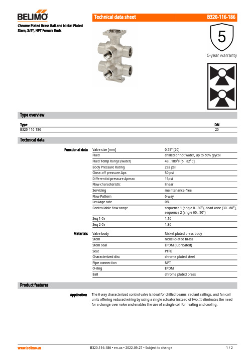
B320-116-186ApplicationChrome Plated Brass Ball and Nickel Plated Stem, 3/4", NPT Female EndsType overviewTypeDN B320-116-18620Technical dataFunctional dataValve size [mm]0.75" [20]Fluidchilled or hot water, up to 60% glycol Fluid Temp Range (water)43...180°F [6...82°C]Body Pressure Rating 232 psi Close-off pressure ∆ps 50 psi Differential pressure Δpmax 15psi Flow characteristic linearServicing maintenance-free Flow Pattern 6-way Leakage rate0%Controllable flow range sequence 1 (angle 0...30°), dead zone (30...60°), sequence 2 (angle 60...90°)Seq 1 Cv 1.16Seq 2 Cv1.86MaterialsValve body Nickel-plated brass body Stem nickel-plated brass Stem seal EPDM (lubricated)SeatPTFECharacterized disc chrome plated steel Pipe connection NPT O-ring EPDMBallchrome plated brassProduct featuresThe 6-way characterized control valve is ideal for chilled beams, radiant ceilings, and fan coil units offering reduced wiring by using a single actuator instead of two. It eliminates the need for a change-over valve and enables the use of a single coil for heating and cooling.B320-116-186 Operation A loop pressure relief is designed into port number two (2). This allows the increased pressureto dissipate to the supply loop on port number one (1). This is intended to release any pressurebuild up in the loop (coil) when the valve is in the closed position and is isolated from the systemexpansion vessel. The change in pressure occurs due to a change in the media temperature inthe coil while isolated from the pressure vessel. The pressure relief does not affect the efficiencyof the system because cross-flow cannot occur between the heating and cooling loops. Thesystem loops (heating/cooling) should share a common expansion vessel to keep the systempressure and volume balanced.Flow/Mounting detailsAccessoriesMechanical accessories Description TypeFixing bracket for 6-way valve DN 15/20ZR-004 DimensionsType DN WeightB320-116-18620 4.63 lb [2.1 kg]A B C D E F G H1H27.5" [191] 3.9" [100]9.0" [229]7.6" [194] 2.0" [51]2.0" [51]2.4" [60]1.2" [30]0.6" [15]LRX24-MFTModulating, Non-Spring Return, 24 V, Multi-Function Technology®Technical dataElectrical dataNominal voltageAC/DC 24 V Nominal voltage frequency 50/60 HzNominal voltage rangeAC 19.2...28.8 V / DC 21.6...28.8 V Power consumption in operation 2.5 W Power consumption in rest position 1.2 W Transformer sizing 5 VAElectrical Connection18 GA plenum cable with 1/2" conduitconnector, degree of protection NEMA 2 / IP54, 1 m 3 m and 5 mOverload Protection electronic thoughout 0...90° rotation Electrical Protectionactuators are double insulated Functional dataOperating range Y 2...10 VOperating range Y note 4...20 mA w/ ZG-R01 (500 Ω, 1/4 W resistor)Input Impedance100 kΩ for DC 2...10 V (0.1 mA), 500 Ω for 4...20 mA, 1500 Ω for PWM and On/Off Operating range Y variable Start point 0.5...30 V End point 2.5...32 VOperating modes optional variable (VDC, on/off, floating point)Position feedback U 2...10 V Position feedback U note Max. 0.5 mA Position feedback U variable VDC variableDirection of motion motor selectable with switch 0/1Manual override external push button Angle of rotation 90°Angle of rotation note adjustable with mechanical stop Running Time (Motor)150 s / 90°Running time motor variable 35...150 s Noise level, motor 35 dB(A)Position indicationMechanically, pluggable Safety dataPower source ULClass 2 Supply Degree of protection IEC/EN IP54Degree of protection NEMA/UL NEMA 2Enclosure UL Enclosure Type 2Agency Listing cULus acc. to UL60730-1A/-2-14, CAN/CSA E60730-1:02, CE acc. to 2014/30/EU Quality Standard ISO 9001UL 2043 CompliantSuitable for use in air plenums per Section 300.22(C) of the NEC and Section 602 of the IMCAmbient humidityMax. 95% RH, non-condensingLRX24-MFTFootnotesSafety dataAmbient temperature -22...122°F [-30...50°C]Storage temperature -40...176°F [-40...80°C]Servicingmaintenance-free Weight Weight1.5 lb [0.70 kg]MaterialsHousing material Galvanized steel and plastic housing†Rated Impulse Voltage 800V, Type action 1.B, Control Pollution Degree 3.AccessoriesGatewaysDescriptionType Gateway MP to BACnet MS/TP UK24BAC Gateway MP to Modbus RTU UK24MOD Gateway MP to LonWorksUK24LON Electrical accessoriesDescriptionType Battery backup system, for non-spring return models NSV24 US Battery, 12 V, 1.2 Ah (two required)NSV-BAT Auxiliary switch 1 x SPDT add-on S1A Auxiliary switch 2 x SPDT add-onS2AFeedback potentiometer 140 Ω add-on, grey P140A GR Feedback potentiometer 1 kΩ add-on, grey P1000A GR Feedback potentiometer 10 kΩ add-on, grey P10000A GR Feedback potentiometer 2.8 kΩ add-on, grey P2800A GR Feedback potentiometer 500 Ω add-on, grey P500A GR Feedback potentiometer 5 kΩ add-on, greyP5000A GR ToolsDescriptionTypeConnection cable 10 ft [3 m], A: RJ11 6/4 ZTH EU, B: 3-pin Weidmüller and supply connectionZK4-GEN Service Tool, with ZIP-USB function, for programmable and communicative Belimo actuators, VAV controller and HVAC performance devicesZTH USElectrical installationINSTALLATION NOTESProvide overload protection and disconnect as required.Actuators may be connected in parallel. Power consumption and input impedance must beobserved.Actuators may also be powered by DC 24 V.Only connect common to negative (-) leg of control circuits.A 500 Ω resistor (ZG-R01) converts the 4...20 mA control signal to 2...10 V.Control signal may be pulsed from either the Hot (Source) or Common (Sink) 24 V line.For triac sink the Common connection from the actuator must be connected to the Hotconnection of the controller. Position feedback cannot be used with a triac sink controller; theactuator internal common reference is not compatible.IN4004 or IN4007 diode. (IN4007 supplied, Belimo part number 40155).Actuators with plenum cable do not have numbers; use color codes instead.Meets cULus requirements without the need of an electrical ground connection.Warning! Live electrical components!During installation, testing, servicing and troubleshooting of this product, it may be necessary to work with live electrical components. Have a qualified licensed electrician or other individual who has been properly trained in handling live electrical components perform these tasks. Failure to follow all electrical safety precautions when exposed to live electrical components could result in death or serious injury.LRX24-MFT Wiring diagramsOn/Off Floating PointVDC/mA Control PWM ControlOverride Control。
电动球阀使用说明书

D1
75 90 100 110 125 135 160 170 200 240 280 345 400 460
D6
40 51 58 66 76 88 110 121 150 176 204 260 313 364
n-φd
4-14 4-18 4-18 4-22 4-22 4-22 8-22 8-22 8-26 8-30 8-33 12-36 12-36 16-36
上海川沪阀门有限公司
电动球阀使用说明书
■ 主要性能指标
公称通径 允许压差 动作范围 泄露量 Q 基本误差
回差 死区 可调范围
15
20
25
32
40
50
65
80
100
125
150
≤ 公称压力(MPa)
0~90°,0~360°
按 GB/T4213-92,小于额定 KV0.01%
±1%
±1%
≤1%(可调)
125 145 160 180 210 240 295 355 410 470 525
46
56
65
76
84
99
118 132 156 184 211
根据阀门压力大小而定。配置机型不同,外形尺寸也不相同。可进入电动执行器页面查阅。
销售电话:021-5186 3046
图文传真:021-5186 3049
PN2.5MPa 法兰连接尺寸
D
95 105 115 140 150 165 185 200 235 270 300 360 425 485
D1
65 75 85 100 110 125 145 160 190 220 250 310 370 430
- 1、下载文档前请自行甄别文档内容的完整性,平台不提供额外的编辑、内容补充、找答案等附加服务。
- 2、"仅部分预览"的文档,不可在线预览部分如存在完整性等问题,可反馈申请退款(可完整预览的文档不适用该条件!)。
- 3、如文档侵犯您的权益,请联系客服反馈,我们会尽快为您处理(人工客服工作时间:9:00-18:30)。
DJFK6型角阀控制器说明书沈阳鑫榆林石油机械有限公司DJFK6型角阀控制器说明书DJFK6型角阀控制器是孔板式液动节流阀上的专用变送器,它将节流阀的开度转换成4—20mA电信号输送给数字显示仪以显示阀的开度。
一、主要技术数据1、最大输出扭矩:150Kgf·m2、输入液压压力:6~8MPa3、测量范围:0°~180°4、精度等级:1.5级5、液路联接:快速接头M22×1.5二、结构与工作原理DJFK6型角阀控制器主要由液压驱动和电信号传感两部分组成。
液压驱动部分由液压缸,齿条和齿轮轴等组成,电信号传感部分由转换机构和位移变送器组成。
工作原理为液压缸推动齿条带动齿轮轴旋转,转动角度为0°~180°,由齿轮轴同步带动孔板式节流阀阀芯转动达到其开、关的目的,同时转换机构推动位移变送器直线移动,使其输出信号随之改变,从而在开度表上显示出孔板式节流阀的开度大小。
三、安装与使用DJFK6型角阀控制器与电动节流管汇控制箱配套使用,控制孔板式液动节流阀开或关,在控制箱面板上操纵手动换向阀通过角阀控制器来控制孔板式节流阀,同时数显表可显示孔板式节流阀的开度大小。
安装调试如结构示意图所示,用过渡接头将角阀控制器和孔板式节流阀阀杆联接起来,用4—M18螺栓通过联接板将角阀控制器固定在孔板式节流阀上。
再将油路管线和航空插头按标牌标定位置对应联接。
转换机构主要由位移变送器、触头、航空插件、调整螺钉等组成。
由于孔板式节流阀阀杆凸出长短不一致,每次安装角阀控制器时需精确对零调整,先将孔板式节流阀关闭,将角阀控制器安装在孔板式节流阀上,松动调整螺钉,移动位移变送器,使阀位数字显示仪读数为“0”,零位调整好后,紧定调整螺钉。
四、说明1、齿轮箱体内应每半年更换一次齿轮润滑机油。
2、联接板由需方自备。
3、过渡接头六角方尺寸依需方而定。
结 构 示 意 图位移变送器航空插头调整螺钉转换机构触头调整螺钉DJFK6 Type Angle Valve ControllerInstruction ManualShenyang Xinyulin Petroleum Machinery Co., Ltd. Instruction Manual for DJFK6 Type Angle Valve ControllerThe DJFK6 Type Angle Valve Controller, specially designed for the orifice plate hydrodynamic throttle valve, is used to convert valve opening into 4—20mA electrical signals and transmit them to the digital indicator so that the valve opening is displayed.1. Main technical details1) Maximum output torque: 150Kgf·m2) Input hydraulic pressure: 6~8MPa3) Range of measurement: 0°~180°4) Accuracy class: 1.55) Connection of hydraulic circuits: quick-acting coupling M22×1.52. Structure and operating principlesThe DJFK6 Type Angle Valve Controller is mainly composed of the hydraulic drive unit and the electrical signal sensing unit. The former consists of the hydraulic cylinder, rack and gear shaft, etc., and the later includes a converter and a displacement transmitter. Its operating principles are as follows: the hydraulic cylinder acts on the rack, which then drives the gear shaft to rotate with a rotation angle ranging from 0° to180°. The core of the orifice plate hydrodynamic throttle valve is synchronously driven by the gear shaft, thus realizing the open/close of the valve. At the same time, the converter drives the displacement transmitter to move along a straight line, making its output signals changed along with it, thus the opening of the orifice platehydrodynamic throttle valve is displayed on the opening position indicator.3. Installation and ApplicationThe DJFK6 Type Angle Valve Controller is designed to use together with an electric throttle manifold to control the orifice plate hydrodynamic throttle valve by operating the hand-directional valve on the control panel. At the same time, the digital indicator will display the opening of the orifice plate hydrodynamic throttle valve. Its installation and commissioning shall refer to the following schematic structural diagram. The process is as follows: connect the angle valve controller with the orifice plate throttle valve rod by using a transition joint, then fix the angle valve to the orifice plate throttle valve by means of a connecting plate fastened with a 4—M18 bolt, lastly, connect the oil way with the aviation plug at the place marked with a label plate.The converter is mainly composed of the displacement transmitter, contracts, aviation plug and adjusting screw, etc. Due to the uncertainty of the protruded length of the valve rod of the orifice plate throttle valve, an accurate zero adjustment is necessary each time the angle valve is installed. The process is as follows: with the orifice plate throttle valve closed, fix the angle valve controller to the orifice plate throttle valve, then slacken the adjusting bolt to move the displacement transmitter until the reading on the valve position digital indicator is zero. Tighten the adjusting bolt after the zero position is well adjusted.4. Notes1)The gear lube oil in the gear box should be replaced on a half-year basis.2)The connecting plate shall be provided by the demanders.3)The hexagonal dimension of the transition joint shall be at the request of the demanders.Schematic structural diagramcontractaviation plugadjusting screwDisplacement transmitterConverteradjusting screw。