ROC-2015控制器 中文常规说明书-正式V1.2 2017-1-15 (1)
ROCO 控制器的中文说明书 ROCO_CN_V4

multiMAUS 概述
概况 ▶ 适合单手操作的人体工学外形 ▶ 带有背光的大屏幕 LCD ▶ 使用旋钮这样的简单方式来控制模型火车的速度与方向 ▶ 带零位锁定的旋钮 ▶ 多语言操作菜单 ▶ 兼容其它符合 DCC / NMRA 标准的控制器 ▶ ROCO 的数码系统可扩展至 个输入设备,可以是另外的 31 Lokmaus 或者 multiMAUS 设备, 或者线路控制设备 (RouteControl) 等等 ▶ 可通过 RS485 和 ROCOMOTION (X-Bus) 升级 特点 ▶ 最多可管理 9,999 台模型火车,并可决定是使用“库模式” 还是“地址模式” ▶ 可以为最多 台模型火车以字母方式命名 64 ▶ 拥有 14,28,128 级“速度级数”(speed step) 控制,并可为模型火车单独设置“速度级数” 20 ▶ 具有灯光控制和 个机车控制“功能”键 (Fuction) ▶ 最多能控制 1,024 个道岔地址 ▶ 可以写入配置变量 (DCC-CVs) 安全 ▶ 可以紧急停止并关闭整个系统 ▶ 可以紧急停止选定的模型火车 ▶ 童锁功能(比如锁定可编程 programming 功能)
中
为了让大家阅读起来清晰明了、简单易懂,我们将说明书分为了几个章节。如果初级用户仅 仅是把 multiMAUS 用于简单地控制火车运行,就不需要读完这本说明书,你只需要阅读 Section 1 基础部分就可以了。 说明书的 介绍的是 multiMAUS 最基本的连接与操作说明。希望了解更多的编程信息 Section 1 Section 3 的用户可以在 看到 multiMAUS 的操作指南。 是作为特殊案例,包括数字模 Section 2 型轨道系统的使用说明。术语表提供了在使用数字模型控制系统时经常遇到的最基本术语的 定义和说明。 最后,祝大家阅读愉快,当然还包括使用 multiMAUS 愉快! Modelleisenbahn GmbH
Lorex 15英寸彩色观察系统说明书

Monitor15” High Resolution LCD Monitor with built in DVR Mouse control interface (mouse included)Trilingual interface (English, Spanish and French)Supports Lorex DDNS (Dynamic Domain Name Service)Commercial grade monitor standWall mountable (mount sold separately)A full range of LOREX Pro Series CCTV cameras available for use with this systemBuilt-In Digital Video Recorder (DVR)Triplex Technology allows for recording, playback or viewing simultaneously.Network Interface for remote viewing over the internet***H.264 video compressionUSB port for Firmware Upgrade, Backup and Image TransferRemovable HDD cradle - easy to remove/upgrade/archiveSATA HDD Designed for Surveillance: Hard Drive is specifically designed for optimal performance in the commercial video security applications.Cameras1/3” Color CCD image sensorExcellent low light sensitivity with 18 IR LEDs provides effective night range of 40ft (12m)*Day/Night mode: Picture automatically switches camera to B&W delivering better clarity in low light conditionsProfessional Grade Weatherproof cameras ideal for indoor/outdoor applications**Wall or Ceiling mountableIndustry standard BNC connector 4 in 1 power adaptor powers all four cameras from one power source 60ft extension cable includedßßßßßßßßßßßßßßßßßßßßßF E A T u R E SL15LD420 SERIESI N T E G R A T E D S U R V E I L L A N C EThis integrated 15” LCD DVR is a perfect fit for a small business application. High resolution LCD screen, robust build with 4 weather proof night vision cameras provides for full versatility. The newest H.264 video compression technology provides longer recording time, coupled with a security certified Hard Disk Drive,this solution is designed to work 24/7. Remote monitoring software with free Lorex DDNS allows you to connect to thesystem from anywhere in the world.SPECIFICATIONS:20’’ x 11.8’’ x 21.2’’ /510 mm x 300 mm x 537 mmContents:15” LCD DVR, 250 GB HDD, Power Adapter,4 x Cameras & stands, 4 x 60ft cables, 1 x 4-in-1 power adaptor for cameras, 1 x mouse, 1 x remote control, 1 x 10ft Ethernet Cable, Software CD, Quick Start GuideMonitor:LCD Panel:Diagonal: 15.0” TFT, Input: TTL / LVDS.LCD Display Resolution: 1024 x 768Video Input: 4CH (4 x BNC)Video Output: Monitor & Spot (BNC x 2)Audio Input: 1 x RCA Audio Output: 1 x RCASplit Screen: Full screen, Quad split Zoom:Available PIP (Picture in Picture): Available LCD Color Resolution: 16.7 M (8 bits)LCD Pixel Pitch: 0.297 mm (H) x 0.297 mm (V)LCD Brightness: 250 cd/m2Control Device: Remote Controller, Mouse (PS2)Power Supply: DC Adapter (12V DC 5A)Dimension: 395 mm(W) x 159 mm(D) x 391 mm(H)Weight (N.W): 8 kgs (W/O HDD)Operation Temperature: 41°F~104°F (5°C~40°C)Operation Humidity:Less than 90%DVR:Storage Capacity: 1 SATA HDD, pre-installed (Maximum 500 GB)Triplex: View/ Playback / Record simultaneously Compression: H.264Recording Speed: 120fps (NTSC)/ 100fps (PAL)Recording Resolution: CIF 352 x 240(CIF), 352 x 288(PAL)Camera:Image Sensor: 1/3” Color CCD Image Sensor Video Format: NTSC / PALEffective Pixels: NTSC: 512H x 492V(252K) / PAL: 512H x582V(298K)Resolution: 420 TV LineScan System: NTSC: 525 Lines 2:1 interlacePAL: 625 Lines 2:1 interlace Sync System: Internal S/N Ratio: More than 48dB Iris:AESAES Shutter Speed: NTSC: 1/60 ~ 1/100,000 Sec.PAL: 1/50 ~ 1/100,000 Sec.Mini Illumination: 0.1 Lux without IR LED, 0 Lux with IR LED Video Output: Composite 1.0Vpp @ 75 ohm Lens/ Lens Mount: 4.3 mm Fixed FOV (Diagonal): 75 degrees Termination:BNCIR LED/ Night Vision Range: 18 IR LED 850nm/ 12m (40 ft.)Power Requirement: 12 V DC +/- 10%Power Consumption: 250 mA Max 12V DC Operating Temp Range: -10°~50° C / 14° ~ 122° F Unit Weight: 560 g Environmental Rating:IP66* IR illumination range up to 40 ft (12M) under ideal conditions. Objects at or beyond this range may be partially or completely obscured, depending on the camera application.** Not for use in direct exposure to water, rain or snow*** Requires a high speed internet connection (minimum upload speed: 256Kb/s, download speed 512Kb/s) and a broadband router – not included. Typical network remote viewing at 1-2FPS.©2008 Lorex Technology Inc.As our product is subject to continuous improvement, Lorex Technology & subsidiaries reserve the right to modify product design, specifications & prices without notice and without incurring any obligation. E&OE3700 Koppers StreetBaltimore, Maryland 21227, USA.Lorex Technology Inc.300 Alden Road, Markham, Ontario L3R 4C1 Canada.4-22102008Spot out Audio In Audio OutRS485。
莱斯康LXP-15效果器中文

安全建议读instructionsread所有安全和操作指示操作单元之前。
保留instructionskeep安全和未来参考操作指令。
注意warningsadhere在单元的所有警告和在操作说明。
遵循instructionsfollow操作和使用说明。
heatkeep单位远离热源,如散热器等,加热器,火炉,等,包括放大器产生热。
ventilationmake确保装置的位置或位置不干扰其适当的通风。
比如说呢单位不应位于一个床,沙发,地毯,或类似的表面可能阻塞通风孔;或者,放在一个柜,阻碍流动的空气通过通风开口。
墙壁或天花板mountingdo不安装单位墙或吸除制造商推荐的。
电力sourcesconnect单位只有一个电源该类型的操作说明中的描述,或作为标记在单位。
接地或偏振*采取预防措施不失败装置的电源线接地或极化。
*在加拿大不适用。
电源线,电源线,protectionroute他们不可能走上或放置物品捏或反对他们,特别要注意电源线插头,插座,方便,在这一点上他们从单位出口。
不使用periodsunplug从装置的电源线出口单位时,要离开很长一段时间未使用的时间。
水和moisturedo不使用单位附近的水-例如,在一个水池,在潮湿的地下室,靠近游泳池,在打开的窗口,等对象和液体entrydo不允许物体坠落或液体要进入外壳的开口。
清洗装置应清洗干净,只推荐由制造商。
servicingdo不尝试之外的任何服务描述在操作说明书。
将所有其他服务的需求合格的服务人员。
损伤需要服务单位应该由合格的服务人员时:电源线或插头已损坏,对象已经下降,或液体已经蔓延到了单元,单位已经暴露在雨,单位出现不正常运行或展览在性能上有明显的变化,该股已下跌,或外壳损坏。
室外天线的接地如果外部天线连接到接收器,确保天线系统接地以提供保护,防止电压潮和内置的静电电荷。
的国家电气规范第810节,ANSI / NFPA No. 70-1984,提供信息方面的适当的接地和桅杆支撑结构,接地的引线到一个天线放电单元,接地导体的大小,位置的天线放电单元,连接到接地电极和接地电极的要求。
1230 用户手册

BRAKE DRIVER TYPE
27 刹车驱动类型
ANTI-ROLLBACK TIME 28 防后滑时间
最小值 最大值 缺省值 单 位
-
-
ON
%
0
10
1
s
0
100
100
%
0
3
0
-
0
1000 400
ms
Emergency Reverse Parameters--------------------------------------
>200HZ 15V
17 低温限流 18 密封性
-25℃电枢电流限为 50%
IP53
10mA 10mA
19 重量 20 尺寸
1.1Kg 164×146×57mm
1)EMC EN50081-2/08.93 EN50082-2: 1995
2)安全性, 防飞车: EN1175
3)满足 UL583 绝缘性测试
0
50
0
%
5
100
100
%
0
3
0
-
MultiMode Parameters ---------------------------------------------
MODE SELECT TYPE 9 模式选择类型
备注:*2 COAST DECEL RATE 10 自由滑行减速率 值越大,减速时间越长
规 格 序号
名称
规格
24V 16KHZ
11 电磁刹驱动电流 2A 12 加速器控制信号 2/3 线,0-5KΩ/0-5V
>500AC
>7.5 为高
13 速度控制类型 14 工作环境温度
BFT控制器、CLONIX或ECOSOL接收器设备用户手册说明书

Q.BO TOUCH QUICK START GUIDE1111OK X X X X OK 1111ON(Default code for channel 1)On CLONIX or ECOSOL receivers, press the RADIO LEARN button.On BFT Controllers with built-in receivers press:Press the O N button at the T-Box and wait 5 seconds.ONPress and HOLD the O N button until the red LED lights up.PressON STEP 1STEP 2STEP 3STEP 4Press and HOLD the O N button until the red LED lights up.PressPress PressON STEP 1(Default code for channel 1)(New code for channel 1)XXXXOK(New code for channel 1)STEP 2STEP 31234OK X X X X OK Press and HOLD the O N button until the red LED lights up.PressPress Press PressON STEP 1(Default programming passcode)(Existing code for channel 1)N N N N OK (New code for channel 1)STEP 2STEP 3NNNNOK(New code for channel 1)STEP 4PROGRAMMING THE T-BOX TO THE RECEIVERCHANGING THE DEFAULT CODEADDING CODES TO A CHANNELGUIA RAPIDA PARA Q.BO TOUCH1111OK X X X X OK 1111ON(Codigo de fabrica del canal 1)En los receptores CLONIX y ECOSOL oprima el boton de programaciónEn los controladores BFT con receptor integrado oprima:Oprima el botón de O N y espere 5 segundos.ONOprima y SOSTENGA el botón de O N hasta que el LED rojo se ilumine.OprimaONSTEP 1PASO 2PASO 3PASO 4Oprima y SOSTENGA el botón de O N hasta que el LED rojo se ilumine.OprimaOprima OprimaON PASO 1(Codigo de fabrica del canal 1)(Nuevo codigo para el canal 1)XXXXOK(Nuevo codigo para el canal 1)PASO 2PASO 31234OK X X X X OK Oprima y SOSTENGA el botón de O N hasta que el LED rojo se ilumine.OprimaOprima Oprima OprimaON PASO 1(Codigo de programacion de fabrica)(Codigo existente para el canal 1)N N N N OK (Nuevo codigo para el canal 1)PASO 2PASO 3NNNNOK(Nuevo codigo para el canal 1)PASO 4PROGRAMAR T-BOX A RECEPTORCAMBIAR EL CODIGO DEL CANAL 1AÑADIR CODIGOS AL CANAL。
euchner msc m2015 安全控制系统使用说明书
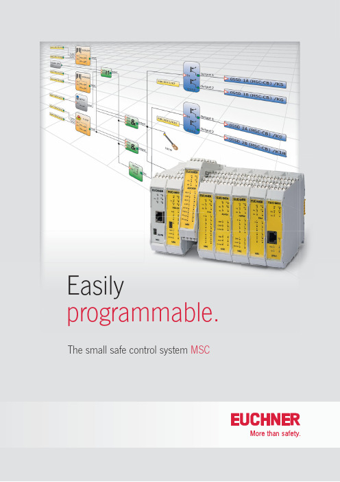
Easilyprogrammable. The small safe control system MSCThe MSC is a universal, freely programmable, modular safety system for the safeguarding of machines and manufacturing equipment. It is suitable for almost all safety-related tasks and can monitor numerous safety-related devices. Programming is easily and conveniently on a PC using the software "EUCHNER Safety Designer". Even with only the base unit MSC-CB it is possible to realize a large number of safety applications with up to 8 inputs and 2 outputs, and that with a housing width of only 22.5 mm.Q Can be expanded easily and specifi callyDepending on the requirements, the MSC off ers a broad range of expansion modules with which the base unit MSC-CB can be expanded almost without limit. The diff erent input and output expansions can be connected to the base unit with the aid of a expansion connector. Various fi eldbus modules can be integrated for straightforward connection to a machine control. The function of the fi eldbus can be specifi cally defi ned in the programming. In this way the control system can be used in a read-only role, or to provide control. All common fi eldbuses are available to suit the related control system.Q Rapid and targeted diagnosticsThe MSC off ers a range of types of diagnostics. The LED indication on the front of all modules provides a straightforward, quick diagnostic feature. In addition it is possible to access directly the program in the base unit with the aid of the software EUCHNER Safety Designer so that the switching state of the inputs and outputs or the logic functions can be checked in detail. Initial setup is signifi cantly simplifi ed in this manner.Q Equipped for an emergencyEach base unit has an internal memory in which the program and all related settings are saved. As an option it is alsopossible to use a separate memory module in the device. A copy of the actual program is automatically saved on this card. It is then possible to replace quickly a faulty device in an emergency, without a PC.Q Protection in compliance with standardsThe small safe control system MSC off ers a high degree of safety. Category 4 and Performance Level e (PL e) in accordance with EN ISO 13849-1 are met by the base unit and all expansion modules.Q Clear softwareThe easy to use and free of charge software "EUCHNER Safety Designer" provides an excellent overview of the logic functions programmed like e-stop, interlock, footswitch. A dedicated module is available for almost every safe device, in this way it is possible to diff erentiate between the emergency stop and an interlock at a glance.The small safe control systemMSCThe expansion modules for the MSCMSC-CE-PN-121315PROF I NET fieldbusMSC-CE-PR-121310PROFINETfieldbusMSC-CE-CO-121312CANopen fieldbusMSC-CE-US-121316USBconnectionMSC-CE-EC-121313EtherCAT fieldbusMSC-CE-EI-121314EtherNET /IP fieldbusMSC-CE-DN-121311DeviceNet fieldbusMSC-CE-MR-122716Modbus RTU fieldbusMSC-CE-MT-122717Modbus TECP/IP fieldbusMSC-CE-EI2-122718EtherNET /IP 2-PORT fieldbusMSC-CE-FI8-121291I nput expansion with8 safe inputsMSC-CE-FI16-121292I nput expansion with16 safe inputsMSC-CE-AZ-FO4-121298O utput expansion with4 safe relay outputsMSC-CE-AZ-FO4O8-121299O utput expansion with4 safe relay outputs8 monitoring outputsMSC-CE-AC-FO2-121294Output expansion with2 safe semiconductor outputsMSC-CE-AC-FO4-121295Output expansion with4 safe semiconductor outputsMSC-CE-CI1-121317D ecentralized 1-channelcommunication moduleMSC-CE-CI2-121318Decentralized2-channelcommunication moduleMSC-CE-SPMO-1213002 Proximity switchMSC-CE-SPM1H-121301MSC-CE-SPM2H-1213042 Proximity switch 1 or 2 HTL encoderM SC-CE-SPM1TB-122721MSC-CE-SPM2TB-122722 2 Proximity switch 1 or 2 TTL encoderM SC-CE-SPM1S-121303MSC-CE-SPM2S-1213062 Proximity switch 1 or 2 sin/cos encoderMSC-CE-AC-FI8FO2-121290I nput and output expansion with 8 safe inputs2 safe semiconductor outputs 2 monitoring outputsMSC-CE-FM4-121293 I nput expansion with4 pressure sensitive mat inputsTransponder-coded safety switches with guard locking Emergency stop devices Electromechanical safetyswitches with safety functionElectromechanical safetyswitches with guard lockingEnabling switchesElectromechanical safetyswitches with guard lockingThe programming interface "EUCHNER Safety Designer"The software "EUCHNER Safety Designer" provides a graphic confi guration interface for programming the small safe control system MSC. This software has a clear layout and is easy and intuitive to operate. A large number of diff erent safety functions (e.g. e-stop, interlock, footswitch) as well as various logic operators (e.g. 1 out of N, AND, OR, INVERTER) are available for the confi guration. With these features even complex applications can be generated easily. The parameter settings are immediately visible on clicking a module. It is not necessary to open any additional windows. This feature provides a quick overview and makes work easier.To setup the system the programming software on a PC is connected directly to the base unit MSC-CB via a USB cable. This saves time during setup and makes troubleshooting easier.The programs prepared are protected by diff erent access levels. In this way inadvertent changes, incorrect operation or changes to the system confi gura-tion are eff ectively prevented. It is of course possible to change the language.121888-05-05/16 S u b j e c t t o t e c h n i c a l m o d i fic a t i o n s ; n o r e s p o n s i b i l i t y i s a c c e p t e d f o r t h e a c c u r a c y o f t h i s i n f o r m a t i o n . © E U C H N E R G m b H + C o . K G · TAEUCHNER GmbH + Co. KG Kohlhammerstraße 1670771 Leinfelden-Echterdingen Germany Tel. +49 711 7597-0Fax +49 711 753316***************Ordering tableItemDescriptionTerminal set*Order no.MSC-CB-AC-FI8FO2-121289Base unit, 8 safe inputs, 2 safe outputs Six contacts 121289MSC-CE-AC-FI8FO2-121290Expansion unit, 8 safe inputs, 2 safe outputs Six contacts 121290MSC-CE-FI8-121291Expansion device, 8 safe inputs Four contacts 121291MSC-CE-FI16-121292Expansion device, 16 safe inputsSix contacts 121292MSC-CE-FM4-121293Expansion device, 4 pressure-sensitive mats Six contacts 121293MSC-CE-AC-FO2-121294Expansion device, 2 safe outputs Four contacts 121294MSC-CE-AC-FO4-121295Expansion device, 4 safe outputs Six contacts 121295MSC-CE-AZ-FO4-121298Expansion device, 4 safe relay outputs Four contacts 121298MSC-CE-AZ-FO4O8-121299Expansion device, 4 safe relay outputs Six contacts 121299MSC-CE-PR-121310Expansion device, PROFIBUS fieldbus Two contacts 121310MSC-CE-DN-121311Expansion device, DeviceNET fieldbus Two contacts 121311MSC-CE-CO-121312Expansion device, CANopen fieldbus Two contacts 121312MSC-CE-EC-121313Expansion device, EtherCAT fieldbus Two contacts 121313MSC-CE-EI-121314Expansion device, EtherNET/IP fieldbus Two contacts 121314MSC-CE-PN-121315Expansion device, PROFINET fieldbus Two contacts 121315MSC-CE-US-121316Expansion device, USB connectionTwo contacts 121316MSC-CE-SPM0-121300Expansion device, 2 Proximity switchFour contacts 121300MSC-CE-SPM1H-121301Expansion device, 2 Proximity switch, 1 HTL encoderFour contacts 121301MSC-CE-SPM1TB-122721 Expansion device, 2 Proximity switch, 1 TTL encoderFour contacts 122721MSC-CE-SPM1S-121303Expansion device, 2 Proximity switch, 1 sin/cos encoderFour contacts 121303MSC-CE-SPM2H-121304Expansion device, 2 Proximity switch, 2 HTL encoderFour contacts 121304MSC-CE-SPM2TB-122722Expansion device, 2 Proximity switch, 2 TTL encoderFour contacts 122722MSC-CE-SPM2S-121306Expansion device, 2 Proximity switch, 2 sin/cos encoderFour contacts 121306MSC-CE-CI1-121317 Decentralized 1-channel communication module Four contacts 121317MSC-CE-CI2-121318 Decentralized 2-channel communication module Four contacts 121318MSC-CE-MR-122716Expansion device, Modbus RTU fieldbus Two contacts 122716MSC-CE-MT-122717Expansion device, Modbus TECP/IP fieldbus Two contacts 122717MSC-CE-EI2-122718Expansion device, EtherNET /IP 2-PORT fieldbus Two contacts 122718AC-PL-B-121308**Expansion connector -121308MSC-M-A1-121309Memory module card-121309AC-SC-02-V04-121319Terminal set 2 contacts screw terminals -121319AC-SC-04-V04-121320Terminal set 4 contacts screw terminals -121320AC-SC-06-V04-121321Terminal set 6 contacts screw terminals -121321C-USB-2.0-A-01,8-MINB-121322USB cable-121322*) Please order separatel **) To expand the base unit MSC-CB an expansion connector must be ordered. One expansion connector is included with all expansion modules.The software "EUCHNER Safety Designer" is included on CD with each base unit MSC-CB (121289).The advantages of MSC at a glance■ Easy to program and multifunctional in use ■ Compact housing for all modules saves space in the control cabinet ■ V arious diagnostics features – can be read easily on the front, in detail in the software ■ Maximum safety (PL e, category 4)■ C onnection of a large number of safety-related devices ■ L ow wiring effort■ C lear programming interface ■ C an be expanded easily and quickly。
AD2015D控制仪表说明书
序言首先感谢您选用本公司研发生产的AD2015D系列显示控制仪表。
AD2015D称重控制仪表,采用世界上最先进的高精度∑-ΔA/D转换芯片和具有高抗干扰性能的单片机为核心,充分考虑到工业现场的复杂性,以精心的软硬件设计,使生产和管理得到有利的保障。
本产品也适用于钢铁、冶金、化工、粮食、饲料等需要配料控制的行业。
控制器具有如下功能及特点◆集称重、显示、通讯和控制于一体◆内部集成的开关电源,电压在185V~245V内可以正常使用◆具有模拟、数字双重滤波功能◆自动错误诊断,易发现和解决问题◆具有自动零位跟踪功能◆可实现上电自动归零◆具有密码权限设置功能,方便管理◆可设置置零范围、滤波强度、波特率等在使用配料控制器之前,请认真阅读本说明书,以确保正确使用并充分发挥其优越性能,并使本设备达到更佳的使用效果。
同时,请您妥善保管说明书,以备今后调试、维护和检修时使用。
如在使用过程中存在疑难问题,请随时与本公司技术支持部联络!相信我们的产品能更好的满足您的需要,让您的事业更上一层楼。
如果您认为27我们产品存在缺点及不足,恳请您批评指正!我们随时欢迎您提出宝贵意见,我们将在最短的时间内作出让您满意的答复!谨在此致谢!27目录第一章产品使用须知.......................................................................................1.1 开箱检查 (5)1.2 安装注意事项 (5)1.3 配线注意事项 (5)1.4 使用注意事项 (5)1.5 维护注意事项 (5)第二章产品技术规格.......................................................................................2.1 技术参数 (7)2.2 外观规格 (7)2.2.1 外形尺寸示意图 (7)2.2.2 前面板介绍 (9)2.2.3 后面板介绍 (9)2.2.4 端子的定义 (10)3.1 进入设置SETUP (13)3.2 进入标定CALIB (15)3.3 功能表 (15)3.3.1 标定菜单 (15)3.3.2设置菜单 (17)第四章功能操作介绍.......................................................................................4.1 标定 (20)4.2 电流环内码值调整 (20)4.3 输入输出测试 (20)第五章串行通讯协议.......................................................................................275.1 CB 920通讯协议 (22)5.1.1 连续输出方式 (22)5.1.2 命令输出方式 (22)5.2 MODBUS通讯协议 (25)5.2.1 MODBUS 连续模式 (25)5.2.2 MODBUS RTU通讯协议 (25)27第一章产品使用须知1.1 开箱检查开箱时,请仔细确认:运输中是否有破损现象;本设备的型号、规格是否与您的订货要求一致。
E+L DC5502莱默尔控制器中文说明书1
E RHARDT + LKRS52-FR5502中文操作說明书目录一、KRS 定型机布边追踪器1.功能……………………………………………………………………2.装设……………………………………………………………………3.安装……………………………………………………………………4.设定编辑………………………………………………………………5.设定DC55.. ……………………………………………………………6.操作和控制盒NT5..……………………………………………………7.最佳的设定……………………………………………………………8.错误讯息………………………………………………………………9.保养维修………………………………………………………………10.技术数据………………………………………………………………3 8 9 11 17 23 24 27 32 32二、红外线布边追踪电眼FR 5502 (数字型)1.总论……………………………………………………………………2.功能……………………………………………………………………3.装设……………………………………………………………………4.安装……………………………………………………………………5.装置设定………………………………………………………………6.操作……………………………………………………………………7.内部设定以及错误讯息………………………………………………8.保养以及维修…………………………………………………………9.配件以及备用零件……………………………………………………10.配线图…………………………………………………………………11.技术数据………………………………………………………………36 36 37 38 39 41 43 46 46 46 46三、KR 52 布边追踪器驱动马达1.安全……………………………………………………………………2.性能设计………………………………………………………………3.功能……………………………………………………………………4.组装……………………………………………………………………5.安装……………………………………………………………………..6.保养维修………………………………………………………………7.损耗品…………………………………………………………………8.配件……………………………………………………………………9.替换注意事项……………………………………………………………10.技术数据…………………………………………………………………48 48 48 50 53 54 54 54 54 60标记说明→:作业要点‖:注意事项! :定型机布边追踪器安全操作事项构造操作说明E + L 定型机布边追踪器操作说明,由总体系统(A)、个别系统(B、C、…W﹚、其他备件表(X)、参数表(Y)、图表(Z)。
欧陆512C操作说明书
单相控制器512C型产品型号HA389196目录目录 (1)概述 (2)机械安装尺寸 (3)电气规格 (4)环境条件 (5)基本接线 (6)接线端说明 (7)系统框图 (10)安装须知 (11)基本设定程序 (12)故障处理 (14)概述SSD512控制器适用于永磁和并磁直流电机的转速和力矩控制。
装置有四种型号:512C/04 4A DC512C/08 8A DC512C/16 16A DC512C/32 32A DC控制器计设在110-415V AC 50/60Hg 单相电流上运行,简单改变控制器上的变换抽头即可使装置使用于供电电压。
控制器采用全波半控可控硅/二极管功率桥块,封装在两块分开的模块中,以便使两模块及控制板可靠接地。
直流电动机的转速采用线性闭环控制,由电枢电压或测速发电机取得反馈讯号使电机转速能在负载波动情况下保持不变。
速度环内的电流环使受控制的电流电平适应于电动机,实际电平值用户可通过电流控制电位器和开关来调节。
由于过大的负载,电机可能堵转,约15秒后控制器会跳闸,由感应引起的严重过电流可以被瞬间过流脱机装置检测到。
磁场及控制电路还提供快熔丝及过电压保护。
警告不先断开系统的所有电流决不能在控制器上工作机械安装尺寸电气规格环境条件外壳:框架安装运行温度:0 - 40℃(40℃以上每度降低1.5%额定值)温度:40℃时相对温度85%(无结露)海拔温度:1000mm以上,每增加100m额定值降低1%重量: 1.5Kg —512C/041.5Kg —512C/081.6Kg —512C/162.9Kg —512C/32转速控制转矩控制基本接线①用于非标电压②信号接地,推荐接保护接地。
如有多台控制器同时使用,应采用一点接地。
③用于电流控制。
接线端说明控制端1.速机反馈:与电动机转速成比例的正向电压(350V最大)。
2.空脚3.转速表输出:0-10V对应转速0-100%,最大负载1mA,有短路保护。
PC15CP泵控制器操作 维护手册说明书
Phone: 800-669-1303 or 801-561-0303Fax: 801-255-2312e-mail:**************************PC15CP PUMPCONTROLLEROperation / MaintenanceManualCONTENTS1PC15CP INSTALLATION (3)1.1PC15CP OVERVIEW (3)1.2PC15CP INSTALLATION (3)1.3PC15CP UTILITIES / HOOK-UP (4)2PC15CP CONTROLLER OPERATION (5)2.1TURNING PUMP ON AND OFF (5)2.2ADJUSTING CONTROLLER (5)2.2.a Suggested Controller Values (5)2.2.b Cycle Rate (6)2.2.c Overlap (6)2.3MAINTENANCE ALARM (6)2.3.a Maintenance Alarm Counter (7)2.3.b Maintenance Alarm Status (7)3REMOTE OPERATION (9)4SPARE PARTS (10)4.1SOLENOID VALVE REPLACEMENT (10)5TROUBLESHOOTING (11)6CONTACT INFORMATION (12)6.1GENERAL CONTACT INFORMATION (12)6.2TECHNICAL SUPPORT (12)6.3REGIONAL REPRESENTATIVES (12)1 PC15CP INSTALLATION1.1 PC15CP OVERVIEWThe PC15CP Pump Controller is designed to operate Trebor’s Purus CP pump. Cross -phase timing results in overlapping pump strokes which produces a near pulse-less pump output.1.2 PC15CP INSTALLATIONThe PC15CP pump controller can be installer in any orientation. Pump controller mounts using two ¼” (6mm) bolts and should be mounted above the level of the fluid feeding the pump. Allow clearance for tubing connectors.Figure 1: Dimension (mm / [in])Controller Air SupplyConnection (50-80 PSIG) Pump Air Supply Connection Remote CapableExhaust Muffler Pump Air SupplyRegulatorAir Flow Control Valves1.3 PC15CP UTILITIES / HOOK-UPUtility PumpAir Inlet: ∙1/4” Diameter (6mm) supply tube.Air Supply: ∙80±5 PSIG (.55±.03 MPa), clean dry air or inert gasPower ∙24VDC - 500mAController Weight: ∙ 4.4 lbs (2.0 Kg)∙Air supply connections between the pump and the pump controller are required.∙24VDC is required to operate the pump controller.o Terminal blocks are insulation displacement type. Insert 18 gage wires into the indicated location and push down lever to complete connection, see Figure .Figure 2: 24VDC Connection2 PC15CP CONTROLLER OPERATIONThe controller is operated by using the buttons located on the PLC, see Table 2-1.2.1 TURNING PUMP ON AND OFFFrom the Home Page, pressing the RIGHT arrow key ( ) will start and stop thecycling of the pump controller. When cycling, a cursor will oscillate under positions“1” & “2”.Figure 3: Controller Cycling2.2 ADJUSTING CONTROLLER2.2.a Suggested Controller ValuesFlow Rate CPM Air Flow Control Overlap- 1-4 LPM: “000030”“3” Turns from closed 20- 3-6 LPM: “000056”“3½” Turns from closed 25- 0-1 LPM: “000010”“1½” Turns from closed 10Please contact Trebor Service Group for any updates on these settings.2.2.b Cycle RateFrom the Home Page, press the LEFT arrow key ( ) to open the Cycle Rate. From there the cycle rate can be adjusted by pressing the UP ( ) and DOWN ( ) arrows.Figure 4: Cycle Rate PagePress the LEFT arrow key ( ) to return to the home page.Press the RIGHT arrow key ( ) to open the Overlap page.2.2.c OverlapFrom the Cycle Rate Page, press the RIGHT arrow key ( ) to open the Overlap page. From here the overlap delay can be adjust by pressing the UP ( ) and DOWN ( ) arrows.Figure 5: Overlap PagePress the LEFT arrow key ( ) to return to the home page.Press the RIGHT arrow key ( ) to open the Maintenance Alarm page.2.3 MAINTENANCE ALARM2.3.a Maintenance Alarm CounterThe Maintenance Alarm Counter page is a visual display indicating how many cycles the pump has run since the last maintenance counter reset. The top 6 digits MSB (mostsignificant bit) displays cycle count in millions while the lower digits LSB (least significant bits) display values up to one million.Figure 6: Maintenance Counter Display PageWhen the maintenance counter MSB value exceeds the alarm setting a service alarm will be initiated. The alarm can be acknowledged and silenced by pressing both the UP ( )and DOWN ( ) arrow keys simultaneously while viewing this page.From the Maintenance Alarm Counter Page the following can be done:∙Pressing the RIGHT arrow key ( ) advances the menu screen to the maintenance alarm page.∙Pressing the LEFT arrow key ( ) or (ESC) key will return the display to the HOME page∙Pressing both the UP ( ) and DOWN ( ) arrow keys simultaneously themaintenance alarm can be silenced.2.3.b Maintenance Alarm StatusThe Maintenance Alarm status page displays the MSB value that the maintenance counter from the previous page must reach in order to activate the maintenance alarm output Q4 (see Figure 7).Press either the UP ( ) or DOWN ( ) arrow key to change the alarm set point value(MSB). This is the value at which service is requested. When this value is zero, themaintenance alarm is deactivated (default state).Figure 7: Maintenance Alarm ON and OFFIn the Figure 6, the MSB shows the factory default setting of 000000. If the setting were set to 000010 and the maintenance counter reached 10 million cycles, the maintenance alarm output (Q4) will be activated (ON) as indicated by the Alarms = ON/OFF line in the display.Pressing both the UP ( ) and DOWN ( ) arrow keys simultaneously while viewing this page will reset the maintenance counter to zero resetting the alarm output.To silence the alarm output (Q4) return to the maintenance counter page by pressing the RIGHT arrow key ( ) then proceeding as outline previously.The following actions can be done from the Maintenance Alarm page:∙Pressing the RIGHT arrow key ( ) will move to the Maintenance Alarm Counter page∙Pressing the LEFT arrow key ( ) or (ESC) key will return the display to the HOME page∙Pressing both the UP ( ) and DOWN ( ) arrow keys simultaneously will reset the maintenance counter to zero resetting the alarm output.∙Pressing either the UP ( ) or DOWN ( ) arrow key will change the alarm set point value (MSB). This is the value at which maintenance service is requested.When this value is zero, the maintenance alarm is deactivated.3 REMOTE OPERATIONTo operate the controller by a remote signal, the following conditions must be met: ∙Input 1 (I1) must have a source input sufficient (>9 VDC) to activate the input as indicated in the display below to activate the remote operation capabilities.∙Input 2 (I2) must have a switched source input sufficient (>9 VDC) to activate the input in conjunction with I1 to turn the controller ON (High Signal) or OFF (LowSignal) as shown in the display below.Figure 8: Remote Mode (ON) Figure 9: Remote Mode (OFF)During remote operation, the controller can be manually stopped by pressing the RIGHT arrow key ( ) from the HOME page, this will locally stop controller oscillation. While in the override stop state, the cursor under the position 8 will be ON (Figure 8).To resume pump operation toggle input I2 changing its state (ON state to the OFF state) resetting output 8 and then turning I2 on again. In order to turn the controller on locallyexit out of remote mode (I1 = OFF) then from the Home Page, press the RIGHT arrow key ( ) will start and stop the control of the pump as normal.Figure 10: Local Override Stop DisplayPump status feedback is provided on output Q3. As indicated in Figure 8 and 9 thisoutput may be wired to provide an indication signal of pump operation4 SPARE PARTSThe following list represents spare parts we recommend for on-site system repair.Consult factory for other parts not shown above.4.1 SOLENOID VALVE REPLACEMENT∙Remove nut from machine screw mounting valve to mounting panel.∙Identify and remove air transfer tubes from push connect ports.∙Disconnect solenoid electrical connectors.∙Remove and replace valve assembly.∙Reverse removal procedure for reassembly.5 TROUBLESHOOTING6 CONTACT INFORMATION6.1 GENERAL CONTACT INFORMATIONWeb: Phone Number: (801) 561-0303Toll Free Number: (800) 669-1303Fax Number: (801) 255-2312Email: *********************************************** Address: Trebor International8100 South 1300 WestWest Jordan, Utah 84088 U.S.A.6.2 TECHNICAL SUPPORTEmail: **************************Phone Number: (801) 244-61566.3 REGIONAL REPRESENTATIVESWeb: 。
- 1、下载文档前请自行甄别文档内容的完整性,平台不提供额外的编辑、内容补充、找答案等附加服务。
- 2、"仅部分预览"的文档,不可在线预览部分如存在完整性等问题,可反馈申请退款(可完整预览的文档不适用该条件!)。
- 3、如文档侵犯您的权益,请联系客服反馈,我们会尽快为您处理(人工客服工作时间:9:00-18:30)。
低压泵
高压泵
图1 工作原理图
冲洗阀
五. 显示板说明
二. 整机基本工作流程如下
无水保护
低 压 泵 储水箱或管网 或前级处理
低压保护 高压保护
冲洗阀
浓水调节
保
高
安
压
过
泵
滤
器 进水阀
RO膜 原件
液位
纯 水 箱
图2 整机基本工作流程图
图3 显示面板 显示面板设有10个指示灯,分别对应指示各点的工作状态。
河北科瑞达仪器科技股份有限公司
六. 后接线端子排列图与接点连接
七. 控制流程图
/
图4 后接线端子图
FS HP
NW
LP LC EC COM
信号采集接线端子的连接 高压低压冲洗选择,短接为低压冲洗,断开为高压冲洗 增(高)压泵超压检测开关接入端子 (常闭,超压断开,不使用时与右上角COM短接) 原水箱低液位或管路压力低检测 (视采用液位开关还是压力开关及安装取样点) 低压泵后侧保安过滤器压力检测开关接入端子 (常开接点,满足压力时闭合) 纯水箱液位检测开关输入端子(常闭,水满断开,低液位闭合) 外部控制接入端子(远程和面板开关控制)控制系统是否运行 上排采集端子的公用端口
输入接线示意图:
高低压冲洗 方式选择
高压超限 保护开关
无水保 低压超限 水位上 护开关 保护开关 限开关
外控开关
图6 简略程序流程图
外控启动
当主控开关或远程控制开关开启,控制器自检,确认水箱不满,依次 打开进水阀、低压泵、高压泵、冲洗阀完成开机并补水至高液位。
运行监控
控制器采集部分以扫描方式巡检各路控制开关逻辑状态,做出开/停及 保护的判断,保证系统安全运行。
运行保护 膜冲洗
系统启动或运行中发生供水不足的保护,待水压恢复之后延迟试启 动,三次试启动如果仍不能持续运行则进入保护状态,等待人为处 理;高压泵超压大于1 秒,系统会保护停机。高压泵间隔1分钟进行试 启动,3次试启动高压泵报警仍未解除,则记忆当前状态,等待人工 处理;小于1秒的异常报警,控制器给予忽略。
EC COM
图5 输入接线示意图
注:输入信号和COM接口严禁直接或间接引入其他有源信号。信号和COM 端子之间连接的必须是无源干接点传感器或信号。
地址:石家庄市新石北路368号 金石工业园2号楼 邮编:050091 电话:0311-83056195/96 E-mail:webmaster@
网站二维码 微信订阅号二维码
河北科瑞达仪器科技股份有限公司
一. 概述
本控制器是一款为小型化一级反渗透制水系统配置的自动运行管理控制器, 只需在外围添加少量的电气元件就可以实现反渗透设备的自动运行,它具有五个 状态的数字输入(DI)端口和四个输出(DO)控制端口,它是一款小型化经济型 控制器。
整机工作原理如方块图1
运行状态指示
三. 主要控制功能
ቤተ መጻሕፍቲ ባይዱ无水保护功能
低压保护功能
RO控制器
纯水箱上水位 纯水箱下水位
电源电压 功耗
环境条件
输出接点负载能力 外形尺寸 开孔尺寸
AC 220V±10% 50/60Hz
<3.5W
1)温度:0~50℃; 2)湿度:≤85% RH 5A/250V AC(阻性负载时) (48×96×80)mm(高×宽×深) (44×92)mm(高×宽)
进水阀
河北科瑞达仪器科技股份有限公司
文件编号
产品名称
发行日 2016 年 4 月 16 日 版本 1.1
ROC-2015 单级反渗透控制器
工作内容 说明书
变更履历
版本 V1.0
发行日 20151210
变更内容 使说明书的输入接线示意图的文字清晰化,未做其他内容的更改。
V1.1 V1.2
20160416
20170115
控制接线端子的连接
AC 220V
220V电源的火线端(220V AC供电时) 电网的零线
COM
控制继电器的公共点
IV
进水电磁阀启/闭控制输出接点(常开,无源)
FV
RO冲洗电磁阀启/闭控制接点(常开,无源)
LM
低压水泵启/闭控制接点(常开,无源)
HM
增压水泵启/闭控制接点(常开,无源)
* 以上所有控制端口都是继电器干接点(无配电)端子,共享COM公共端子。
当前级预处理系统处于冲洗或再生时,保安过滤器出现脏堵 时,不能向RO系统提供正常的供水压力(即低压不足),控制 器暂时关闭整个RO系统。此时“LOW PRESS”指示灯点亮。同时 蜂鸣器鸣叫。
此后控制器会不停的对低压保护开关进行检测,压力恢复1 分钟后RO控制系统进行首次试启动,运行RO系统。
如果系统再次出现低压保护则再次暂停RO系统的运行,程 序设置了三次试启动,当三次试启动不能成功,系统进入死锁保 护状态,面板低压保护指示灯一直保持,提示停机的原因,等待 人为处理后按复位键解锁重新开启。
ROC-2015 单级反渗透控制器
POWER INLET VALVE M1 M2 RO FLUSH VALVE FULL
LOW FEED PRESS
LOW PRESS HIGH PRESS
控制器电源接通指示灯 进水电磁阀开启指示灯 低压水泵运行指示灯 高压水泵运行指示灯 反渗透膜组处于制水状态指示灯 冲洗电磁阀开启指示灯 纯水箱水满指示灯 水源低压或无水报警指示灯 (取自预备水箱低液位开关时做无水报警) 低压报警指示灯(保安过滤器和电磁阀监督) 高压超压报警指示灯
当纯水箱液位处于预置的低液位时,控制器立即启动RO系 统产水,直至纯水箱液位达到预定的高液位时系统完成膜冲洗自 动转入待机。
在保护装置和状态运行正常时,系统每次上电进行首次膜冲 洗,之后每次低液位制水都要进行膜冲洗,产水箱水满后自动完 成膜冲洗。
四. 主要技术指标
无水保护 低压保护 高压保护 外控操作
高压保护功能 纯水箱液位 控制功能 膜冲洗功能
用作水源的监控,当原水出现断水(储水箱低水位,管路压 力太低),防止系统空转,控制器停止整个RO系统的运行,面 板上的“LOW FEED PRESS” 指示灯点亮,同时蜂鸣器鸣叫。此后 控制器将不间断检测无水开关,如果供水压力或液位恢复正常, 控制器重新启动RO系统运行。
在一些使用高压保护的系统中,系统出现超压,控制器主动 关闭整个RO系统,“HIGH PRESS”指示灯点亮,待高压消除1分钟 后,控制器进行首次试运行,如出口压力依旧超压,系统再次进 入保护状态。高压保护程序设置有三次试启动,当三次启动均不 能恢复正常运行,系统进入死锁保护状态。同时蜂鸣器鸣叫。
☆ 如果系统不采用高压保护,将此端子进行短接 (COM+HP)
加入了冲洗方式选择的详细说明 电磁兼容性版本,功耗由原≤2W,改为<3.5W,并增加了接线说明的注意事项
制定部门 研发部
审定 2016.04.16
校对 2016.04.16
承办 2016.04.16
ROC-2015 单级反渗透控制器
/
目录
1. 概述…………………………………………………………………………………………1 1. 整机基本工作流程 ……………………………………………………………………1 3. 主要控制功能……………………………………………………………………………1 4. 主要技术指标……………………………………………………………………………1 5. 显示板说明 ………………………………………………………………………………1 6. 后接线端子排列图与接点连接 ……………………………………………………2 7. 控制流程图………………………………………………………………………………2
初次上电开机,系统执行30s膜冲洗,运行中每次开机或水满冲洗 10s,连续运行3h或水满待机3h,自动介入冲洗10s。
变更与扩展 在工程应用中,用户不适合以上工作方式时,可书面传真工作模式要 求,以便改写与之适应的工作程序。
操作说明书
ROC-2015 单级反渗透控制器
V1.2
淘宝店二维码
FS HP NW LP LC