读卡器控件安装说明
罗斯拉AY-x12C系列PROX读卡器安装和用户手册说明书

AY-x12C SeriesRosslare PROX ReadersInstallation and User Manual1. IntroductionThe AY-x12C is a series of RFID proximity card readers to be installed for use with access control systems.The AY-x12C series reads the proximity card and transmits its data to the access control system, using Wiegand 26-Bit, Clock & Data, and serial RS-232 outputs.Figure 1: AY-x12C Series2. InstallationCard readers are to be used with control panels whose power supply is UL Listed Class 2 or equivalent.2.1 Installation KitThe installation kit consists of the following items to be used during the installation procedure: ▪ One self-adhesive mounting label template ▪ Two pan head mounting screws and screw anchors ▪ One Torx key tool ▪One Torx security screw2.2 MountingBefore mounting, you should determine the best location for the reader.To mount the reader:1. Peel off the back of the self-adhesive mounting label templateand place it at the required mounting location. 2. Using the template as a guide, drill two holes (hole size andposition is indicated on the mounting template) for mounting the reader onto the surface. 3. Insert a screw anchor into each hole.4. Drill a 10-mm (7/16”) hole for the cable. If mounting on metal,place a grommet or electrical tape around the edge of the hole. 5. Remove the screw from the bottom of the unit.6.Remove the reader's snap-off front cover.For the Q model, remove the cover by gently sliding it up and then pulling it apart.7. Insert the unit’s cable wire into the cable hole and wire the unitas described in Section 3.3. A linear type power supply is recommended. 8. Align the two holes of the reader with those drilled in the walland firmly attach the reader to the wall with two screws (Figure 2)Figure 2: Inserting Mounting Screws (similar for all models)9. Relocate the front cover onto the reader.10. Secure the front cover by using the supplied security Torx screw.A Torx security screw tool is provided to tighten the security Torx screw.2.3 WiringThe AY-x12C is supplied with a 10-conductor 56-cm (22-in.) pigtail with exposed wires coated with solder. To connect the reader to the controller:1. Select the appropriate connections according to Table 1.Table 1: Wiringand strip the insulation from the wires about 1.2 cm (½"). 3. Splice the reader’s pigtail wires to the corresponding controllerwires and cover each joint with insulating tape. 4. If the tamper output is being utilized, connect the purple wire tothe correct input on the controller. 5. Trim and cover all unused conductors.• When using a separate power supply for the reader, this supplyand that of the controller must have a common ground. •The reader’s cable shield wire should be preferably attached to an earth ground, or a signal ground connection at the panel, or power supply end of the cable. This configuration is best for shielding the reader cable from external interference.AY-M12C AY-H12C AY-L12C AY-K12C AY-Q12C3. Operation Instructions3.1TestingOnce the reader is wired to a power supply and to the controller, you should test the reader. To test the reader: 1. Power up the reader.Upon power up, the reader flashes and beeps once during Self-Test. The LED then turns red indicating the readers has entered Standby mode.2. Apply a PROX card to the reader.The reader flashes and beeps once indicating the card has been read successfully.3.2 Data Output Mode LineThe Data Output Mode Line is used to select whether the reader outputs in Wiegand 26-Bit, RS-232, or Clock & Data format. When the Mode Line is open, the reader outputs Wiegand 26-Bit. When the Mode Line is pulled to high, the reader outputs RS-232. When the Mode Line is pulled to ground, the reader outputs Clock & Data.3.3LED ControlThe reader has a bi-color (green/red) LED and two LED control lines, one for green LED control (orange wire) and the other for the red LED control (brown wire).When both LED control lines are open, the reader self manages the LED behavior. In Standby mode, the LED remains red. When a card is presented, the LED flashes green and then returns to red.When a LED control line is pulled to ground, the LED changes to the related LED color and the self-management is disabled. If both LED control lines are pulled to ground, the LED is amber colored.3.4 Buzzer ControlWhen the Buzzer control line (yellow wire) is open, the reader self manages the buzzer behavior and beeps when a card is readsuccessfully. When the Buzzer control line is pulled to ground, the buzzer sounds.3.5 Hold ControlWhen the Hold control line (blue wire) is open, the reader functions normally. When the Hold line is pulled to ground, the hold function is activated. When active and a card is read, no card data is sent on the Wiegand lines; however, the reader continues to buffer the last card ID read and sends that ID data when the Hold line is released.4. Technical Specifications4.1Electrical Characteristics** Measured using a Rosslare proximity card or equivalent. Range alsodepends on installation environment, reader voltage, and proximity to metal.4.2 Environmental CharacteristicsDeclaration of Conformity▪This device complies with Part 15 of the FCC Rules. Operation is subject to the following two conditions:▪This device may not cause harmful interference.▪This device must accept any interference received, including interference that may cause undesired operation.▪Changes or modifications not expressly approved by the party responsible for compliance could void the user's authority tooperate the equipment.This equipment has been tested and found to comply with the limits for a Class B digital device, pursuant to part 15 of the FCC Rules. These limits are designed to provide reasonable protection against harmful interference in a residential installation. This equipment generates, uses, and can radiate radio frequency energy and, if not installed and used in accordance with the instructions, may cause harmful interference to radio communications. However, there is no guarantee that interference will not occur in a particular installation. If this equipment does cause harmful interference to radio or television reception, which can be determined by turning the equipment off and on, the user is encouraged to try to correct the interference by one or more of the following measures:▪Reorient or relocate the receiving antenna.▪Increase the separation between the equipment and receiver. ▪Connect the equipment into an outlet on a circuit different from that to which the receiver is connected.▪Consult the dealer or an experienced radio/TV technician for help.Limited WarrantyThe full ROSSLARE Limited Warranty Statement is available in the Quick Links section on the ROSSLARE website at.Rosslare considers any use of this product as agreement to the Warranty Terms even if you do not review them.Contact InformationUnited States and Canada Rosslare Security Products, Inc. Southlake, TX, USAToll Free: +1-866-632-1101 Local: +1-817-305-0006 Fax: +1-817-305-0069******************************* EuropeRosslare Israel Ltd.22 Ha'Melacha St., P.O.B. 11407 Rosh HaAyin, IsraelTel: +972-3-938-6838Fax: +972-3-938-6830*******************************Latin AmericaRosslare Latin AmericaBuenos Aires, Argentina*******************************ChinaRosslare Electronics (Shenzhen) Ltd.Shenzhen, ChinaTel: +86-755-8610-6842Fax: +86-755-8610-6101*******************************Asia Pacific, Middle East, AfricaRosslare Enterprises Ltd.Kowloon Bay, Hong KongTel: +852-2795-5630Fax: +852-2795-1508*********************************IndiaRosslare Electronics India Pvt Ltd.Tel/Fax: +91-20-40147830Mobile: +91-9975768824*****************************CERT ISO 9001ISO 14001。
身份证读卡器驱动安装指南.

注意事项为保证系统使用正常,请先按以下步骤对IE浏览器进行设臵:1.打开工具->Internet选项->安全,选择“受信任的站点”,点击“站点”,将本系统网址添加为可信任站点,如图1,图2:图1图22. 打开工具->Internet选项->安全,选择“Internet”,点击“自定义级别”,将“本地文件上载到服务器包含本地目录路径”,设臵为启用,如图3,图4。
图3图4身份证读卡器驱动安装1、在江苏省建设考试培训网中下载“身份证读卡器驱动程序包”,见下图:2、下载驱动程序后,进行驱动的安装:(1),如果电脑系统是windowXP,运行程序,安装成功即可。
见下图:注意:正常安装成功后,在电脑的设备管理器中会有一个叫密码设备的选项(通过鼠标右击“我的电脑”,选择“管理”,可进入设备管理器)如果没有密码设备,出现下图中的情况时,请按照下面的方法解决:在设备管理器界面下,右击“USB device”,选择“更新驱动程序软件”进行下一步,如图4所示。
在“更新驱动程序软件”界面下选择“浏览计算机以查找驱动程序软件”继续完成下一步。
(2)如果电脑是windows7系统,请鼠标右击以管理员身份运行,直至运行成功:此时,可以将读卡器连接电脑进行正常读卡。
如果读卡器还是不能正常工作,在插入读卡器时,在电脑右下方弹出两个消息框,如图1和图2所示。
图1图2此时在设备管理器当中会出现如下情况,如图3所示。
图3该图表明已识别到设备接入,手动添加驱动程序之后才能够使用。
Windows7中的设备管理器的查看方式:“开始”菜单→控制面板→设备管理器。
确保驱动程序安装包中的“Win7_64bit驱动”文件夹下包含以下文件:●samcoins.dll●USBDrv.sys●USBDrvCo.inf●sdt_s_drv_x64.cat在设备管理器界面下,右击“未知设备”,选择“更新驱动程序软件”进行下一步,如图4所示。
23--PRO22R2(双读卡器模块)安装说明书

23--PRO22R2(双读卡器模块)安装说明书PRO-2200双读卡器模块安装手册(PRO22R2)目录警告及提示 (1)声明 (2)拆包装程序 (2)运输指导 (3)保修期 (3)保密性 (3)描述 (3)设置 (4)LED 指示灯 (5)电源 (5)通信 (6)读卡器连线 (6)报警输入连线 (7)控制输出连线 (7)安装说明 (8)推荐安装步骤 (8)参数总录 (9)警告及提示警告安装前,请断开所有外部供电电源。
在给设备上电前,请确认电源的供电电压在设备要求的电压范围内。
在设备未安装完毕前,不要给系统上电。
请勿必遵守此警告,否则可能会造成人身伤亡和设备损坏。
警告消防及安全性提示在使用读卡器的关键出入口、消防通道、栏杆、电梯等,根据消防和安全条例的要求,必须安装有其他的应急出口。
这些防火和安全条例各地不尽相同,所以采用电子设备控制门或其他通道系统时,必须取得当地消防机构的认可。
例如,使用出门按钮,在某些地区,可能是不可法的。
在许多应用场所,出门指示要清晰明了,一看就懂,容易使用,而不需要事前告知,这是安全条例的要求。
所有的许/认可要以书面方式确认。
不要接受口头的认可,口头认可不具有法律效律。
Engineered Systems不建议使用PRO2200 或相关产品作为主要的报警监控系统。
主要的报警监控系统应该符合当地消防和安全条例的要求。
安装商必须定期对系统进行测试,并指导最终用户进行适当的日常测试。
不做定期的测试维护,当最终用户出现使用问题时,安装商应对造成的损失负有责任。
警告所有外箱必须正确接地。
警告所有电锁需做电磁保护,可安装S-4。
Engineered Systems建议用户选用使用直流供电的电锁。
本手册可以在未通知的情况下进行更改。
提醒若运输过程中造成损坏,请在索赔中填写承运商。
提醒静电可损坏CMOS集成电路和模块。
为防止静电破坏需遵循以下操作:在运送所有电子设备,包括已安装的读卡器,使用防静电所装袋或防静电容器。
加密版二代身份证读卡器驱动安装手册

加密版二代身份证读卡器驱动安装手册
安装步骤如下:
1、在控制面板—添加删除程序中,卸载以前安装的华视和华旭的驱动。
2、将C盘中的CertReader文件夹删除,如果删除不了,则将该文件夹移动到桌面。
3、到群文件里下载加密版二代身份证读卡器驱动安装文件,安装二代证读验机具USB驱动和华视阅读器插件。
4、安装完成后,连上二代身份证读卡器并放上身份证,用火狐浏览器打开Test文件测试,如果能读出身份证信息,表明驱动安装成功。
5、登陆isale系统测试,到客户信息修改界面,点击读卡按钮,如果能读出身份证信息和照片,表明新驱动安装成功;如果不能读出身份证信息,卸载火狐浏览器重装后,再重新测试。
firefox_Setup_25.0.1_chs 为火狐浏览器安装包。
安装使用说明书

IC卡读写器安装使用说明书使用读写器前需要安装驱动程序:一、将读写器插到电脑USB插口上,系统自动弹出硬件安装向导;二、插入光盘点击下一步进行自动安装驱动程序;如果自动安装无法进行请选择:【从列表或指定位置安装(高级)(S)】单击【下一步】无光盘光驱的电脑请指定驱动所在的目录,如下图:单击【下一步】单击完成结束安装。
读写器常见问题解答Q:读写器为什么读系统卡时比较慢?A:软件版本请升级到6.11.1.0以上,新版本软件已修正此问题,老版本软件设置的默认串口是COM1,而USB读写器是虚拟COM口,软件自动在COM1~COM6中自动查找,所以启动读取系统卡时间偏慢,另一方面电脑的处理速度软件在检测COM口是否有读写器就会有延时。
如果延时太长请参照下面的方法修改串口号操作!Q:为什么我装上了驱动还是找不到发卡器检测不到系统卡?A: 软件版本请升级到6.11.1.0以上新版本软件已修正此问题,可能电脑上有多个COM口在使用,而读写器的COM口排在了COM7以后,软件就不会自动检测COM6以后的COM 口,这时就无法找到发卡器设备就检测不到系统卡。
参照下面的方法修改串口号操作!Q:为什么读卡器不读卡?A:软件版本请升级到6.11.1.0以上,新版本软件已修正此问题,使用读卡器的过程中也使用相同的USB转串口的设备进行插拔式有可能使得读卡器原先的COM口号发生改变,这时可以通过重启软件并重新插拔读写器使其恢复。
或者通过手工设置COM口的序号更新电脑硬件使其生效。
修改串口号操作方法如下:右键点击【我的电脑】选择【属性】单击【硬件】:单击【设备管理器】点击【端口(COM 和LPT)】加号键展开菜单右键读写器所使用的COM口点击属性进入菜单【端口设置】【高级..】选择COM1口点击【确定】。
点击【是】,完成操作。
2_身份证读卡器操作使用说明
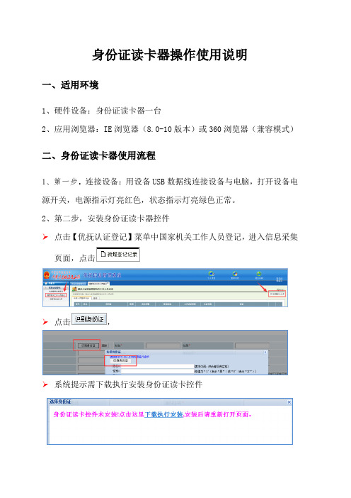
身份证读卡器操作使用说明
一、适用环境
1、硬件设备:身份证读卡器一台
2、应用浏览器:IE浏览器(8.0-10版本)或360浏览器(兼容模式)
二、身份证读卡器使用流程
1、第一步,连接设备:用设备USB数据线连接设备与电脑,打开设备电源开关,电源指示灯亮红色,状态指示灯亮绿色正常。
2、第二步,安装身份证读卡器控件
➢点击【优抚认证登记】菜单中国家机关工作人员登记,进入信息采集页面,点击
➢点击,
➢系统提示需下载执行安装身份证读卡控件
➢点击下载执行安装,系统提示保存读卡器控件
➢双击控件、安装程序。
3、第三步,安装完成后必须重启浏览器,身份证读卡器控件才能应用。
三、身份证信息读取成功提示
将身份证放在读卡器上,点识别按钮,读卡器界面如图
读取成功,姓名、性别、民族、身份证号码、出生日期、年龄、起止日期、签发机关、身份证地址、身份证头像、身份证正反面照片信息全部自动上传系统。
GemPC410读卡器安装手册

GemPlus GemPC410读卡器安装手册目录一、对老证书用户 (1)二、安装读卡器驱动程序 (1)三、卸载读卡器驱动程序 (2)一、对老证书用户老证书系统中使用的GemPC 410读卡器不需要安装驱动程序,因此使用新证书系统前不需要卸载原来安装的驱动程序。
为了使新证书系统运行更加稳定最好卸载SAgent客户端软件。
在登录新证书系统前必须先恢复IE浏览器的Internet 代理设置,即取消SAgent作为IE浏览器一级代理。
如果您不知道如何设置Internet代理请联系您公司的网管或者相关IT人员。
GemPC 410读卡器支持工行使用的全部两种IC卡(GemPlus 金邦达、G&D 捷德),支持从Windows98(二版)到WindowsXP的操作系统平台。
请特别注意:GemPlus GemPC410读卡器和GemPlus GCR410读卡器外形十分相近,请根据读卡器底部的铭牌区分两种读卡器。
二、安装读卡器驱动程序下面以Windows2000操作系统为例演示读卡器驱动程序的安装和卸载过程,其他操作系统上的安装过程可能会略有差别,但是大体过程是相同的。
Step 1:关闭计算机,连接好读卡器(PS2口和COM口都要连接好),重新启动计算机。
注意,PS2口要和键盘接在一起,如果和鼠标接在一起会导致读卡器无法工作。
Step 2:运行驱动程序光盘中release software\drivers\gemplus目录下的setup.exe。
Step 3:在“读卡器类型”下拉框中选择“GemPC410”,在“操作”对话框中选择“安装”,点击“确定”继续。
Step 4:安装读卡器驱动程序需要一定时间请耐心等待。
Step 5:安装程序提示:如果您是第一次安装读卡器驱动程序,整个安装过程大约会持续2分钟,在这段时间内安装程序会暂时失去相应。
Step 6:安装程序提示您连接好读卡器,点击“确定”继续。
Step 7:安装程序完成并提示您重新启动计算机,请保留您还未保存的工作。
IC卡读卡器技术要求安装调试使用说明
IC卡读卡器技术要求安装调试使用说明
一、IC卡读卡器技术要求:
1.读卡速度快:IC卡读卡器应具备高速读卡功能,能够在短时间内读取、处理IC卡中的信息。
2.支持多种卡类型:IC卡读卡器应支持各种卡类型,如CPU卡、磁条卡、非接触式射频卡等。
3.安全性保证:IC卡读卡器应具备数据加密和密钥管理功能,确保读取和传输的数据安全。
4.良好的兼容性:IC卡读卡器应与各种操作系统、设备接口兼容,以确保在不同平台上的正常工作。
5.抗干扰能力强:IC卡读卡器应具备抗静电、抗干扰等功能,确保在各种环境下的正常读卡操作。
二、安装调试使用说明:
1.安装:将IC卡读卡器与计算机或其他设备适配好接口,确保电源连接正确。
2.驱动安装:根据读卡器的型号,在计算机上安装相应的驱动程序,并完成相应的配置。
3.软件设置:根据实际需求,在计算机上安装与IC卡读卡器配套的管理软件,并进行相应的设置。
4.调试:打开管理软件,在IC卡读卡器上放置IC卡,并连接电源。
通过软件界面,进行读卡操作,并确保读取到正确的卡信息。
5.用户操作:为用户提供详细的操作说明,包括将IC卡正确地靠近读卡器、插入IC卡、输入密码等。
并在读卡器上提供相应的指示灯和声音提示,以方便用户操作和了解读取结果。
7.维护保养:定期清洁读卡器的读卡口、插卡槽等部位,以确保读卡器的正常工作。