TrackGIS使用说明文档
XTracks说明书
Xtracks系列轨道使用说明书此文着重对XTracks3.18版本中的模型进行简要介绍,寄希望能为线路制作者、改造者提供参考,使新建的和改造的MSTS中国线路更加精美。
建议所有新建线路的作者尽量在初始MSTS+XTracks3.18的平台下直接铺轨,这样,体验线路的朋友就不必再去下载覆盖GLOBAL文件,大家也能跳出墨守成规的旧铺法的俗套了。
下面就按轨道模型的分类进行介绍(本文只介绍普通A轨,其它轨道诸如SR轨、隧道轨请另寻相关教程)。
A1t?mStrt.s:直轨直轨很简单,在此不多作介绍。
只需注意,小数点在这里表示为“_”,即:0.3m的模型名称为A1t0_3mStrt.s。
A1t?r?d.s:曲线轨在这里,?r代表了曲线半径,?d代表了曲线的圆心角。
在XTracks3.18中,A1t类的曲线半径有:60、75、90、120、150、164、190、250、300、365、375、500、700、750、865、1000、1034、1200、1500、1534、2000、2588、3000、3088、4000、6000、8000及15000;A2t类的曲线半径有:250、300、375、500、750、1000、1500、2000、3000、4000、6000、8000及15000。
圆心角主要有1d、5d、10d及20d(个别模型度数不全)。
至于具体该用哪种曲线轨道,还要针对具体线路并结合“技规”来选择铺设。
A1Brdg??.s:桥梁轨桥梁轨主要包括:直轨、曲线轨、10d道岔和7d的Y型岔,A2t的桥梁轨只有曲线轨模型。
这里还要说明,桥梁轨道模型是带护轨的,桥梁轨道区间须以A1tBrdgEnd.s作为两端,A1tBrdgEnd.s的逻辑长度相当于2.6m直轨的长度。
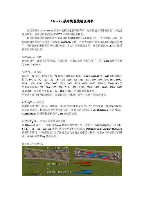
A1tDblSlip?d.s:双向复合交分道岔组件在XTracks3.18中,不需再用Xover轨道来组装复合交分道岔了。
A1tDblSlip?d.s共有3d、6_3d、7_5d、10d、10d150r五个,两端分别要和对应的A1tPnt?dLftSlip.s、A1tPnt?dRgtSlip.s 模型组合使用。
trackvis使用手册

Hale Waihona Puke FAQWhy do I get funny looking “nonsense” tracks? 首先, 你应该确认用来重建的图像有正确的图像方向信息. 第二, 不同的核磁仪器制造商会有不同的翻译图像方向的方 法. 这正是 “方向补丁” 被引进到Diffusion Toolkit的原因. Please refer here for more information. 从我们有限的 经验来看, Siemens数据通常不需要任何方向补丁, 但GE和 Philips数据经常需要应用"Invert Y". 具体方法参见:/dtk/?subsect=gui
FAQ
TrackVis是什么? TrackVis 是一个软件能可视化并分析纤维跟踪产生于核磁 图像 by 弥散张量成像(DTI), 弥散光谱成像(DSI) 和其他弥 散图像科技.
FAQ
TrackVis, Diffusion Toolkit的区别是什么? 为什么它们是 分开的? TrackVis 是一个纤维追踪可视化和分析程序. 它不执行实际 的纤维追踪. Diffusion Toolkit 是一套工具能重建弥散图像 数据和生成纤维追踪数据给TrackVis 用来可视化. 因为这两 套工具是分开开发和维护的,而且每一个都有不同的杰出 的功能, 所以我们决定把它们分开维护和升级. 你非常需要 这两个软件来执行完整的弥散数据处理和.
TrackVis使用手册
简介
TrackVis 是一个软件工具能可视化并分析来自弥散核磁成像的纤维 追踪数据 (DTI/DSI/HARDI/Q-Ball)纤维跟踪。TrackVis的特点包括: 1、跨平台. 可在Windows, Mac OS X and Linux工作。 2、追踪过滤器的多样性(追踪选择方法) 允许用户轻松探索和定位 特定的一簇纤维。 3、Multiple rendering modes with 可定制的 scalar-driven 颜色 编码。 4、实时参数调整和3D渲染。 5、打开跟踪数据文件的格式允许用户将自定义标量数据集成到跟 踪文件并可视化和分析它.保存和恢复场景在XML风格的场景文件. 6、 tracks and ROIs的统计标量分析。 7、同步实时多重数据分析和显示允许时点and/or 主题比较.在相 同的数据集同步分析和显示,也可以通过远程网络进行。 8、前期在线实时参数调整.没有乏味的弹出对话框。
arcgis追踪用法
arcgis追踪用法ArcGIS是一款强大的地理信息系统(GIS)软件,提供了丰富的地理空间数据获取、管理、分析和可视化功能。
在ArcGIS中,追踪(Tracking)功能可以用于跟踪物体、人员或车辆等物理实体的移动和变化。
ArcGIS中的追踪功能可以通过以下方式实现:1.创建追踪图层:在ArcMap或ArcGIS Pro中,可以创建一个追踪图层来存储追踪数据。
追踪图层可以是点、线或面图层,用于记录物体的位置、路径或范围。
可以通过手动绘制或导入外部数据来创建追踪图层。
2.配置追踪设置:在追踪图层中,可以配置各种追踪设置,包括追踪的时间间隔、距离阈值、速度限制等。
这些设置可以根据实际需要进行调整,以满足追踪的准确性和精度要求。
3.运行追踪操作:在追踪设置完成后,可以运行追踪操作来开始记录追踪数据。
可以手动输入位置信息,也可以通过GPS设备或其他传感器自动获取位置数据。
运行追踪操作后,追踪图层将记录位置数据,并在地图上显示物体的移动轨迹。
4.分析和可视化追踪数据:一旦追踪数据被记录下来,就可以使用ArcGIS的分析工具进行各种空间分析,如路径分析、时空模式分析等。
此外,还可以使用符号化、标签、动画等功能来可视化追踪数据,以便更直观地展示物体的移动和变化。
拓展:除了基本的追踪功能,ArcGIS还提供了其他有关追踪的高级工具和扩展功能。
例如,追踪分析工具可以对追踪数据进行深度分析,包括热力图生成、路径聚类、轨迹相似性计算等。
此外,ArcGIS还支持与其他系统(如车载终端、无人机、传感器网络)集成,以实现更复杂的追踪应用场景。
总而言之,ArcGIS的追踪功能可以用于各种领域,如交通管理、物流追踪、环境监测等,帮助用户更好地理解和利用地理空间数据。
AXIS Digital Autotracking 1.1 使用和管理指南说明书

INSTALLATION GUIDE AXIS Digital AutotrackingAbout This DocumentThis manual is intended for administrators and users of AXIS Digital Autotracking,and is applicable to release1.1.It includes instructions for using and managing the application.Previous experience of networking will be of use when using this product.Some knowledge of UNIX or Linux-based systems may also be beneficial,for developing shell scripts and ter version of this document will be posted to the Axis website,as required.See also the product’s online help,available via the web-based interface.LiabilityEvery care has been taken in the preparation of this document.Please inform your local Axis office of any inaccuracies or omissions.Axis Communications AB cannot be held responsible for any technical or typographical errors and reserves the right to make changes to the product and manuals without prior notice.Axis Communications AB makes no warranty of any kind with regard to the material contained within this document,including,but not limited to,the implied warranties of merchantability and fitness for a particular purpose.Axis Communications AB shall not be liable nor responsible for incidental or consequential damages in connection with the furnishing,performance or use of this material.This product is only to be used for its intended purpose.Intellectual Property RightsAxis AB has intellectual property rights relating to technology embodied in the product described in this document.In particular,and without limitation,these intellectual property rights may include one or more of the patents listed at /patent.htm and one or more additional patents or pending patent applications in the US and other countries.This product contains licensed third-party software.See the menu item “About”in the product’s user interface for more information.This product contains source code copyright Apple Computer, Inc.,under the terms of Apple Public Source License2.0(see /apsl).The source code is available from https:///bonjour/Trademark AcknowledgmentsApple,Boa,Apache,Bonjour,Ethernet,Internet Explorer,Linux, Microsoft,Mozilla,Real,SMPTE,QuickTime,UNIX,Windows,Windows Vista and WWW are registered trademarks of the respective holders. Java and all Java-based trademarks and logos are trademarks or registered trademarks of Oracle and/or its affiliates.UPnP TM is a certification mark of the UPnP TM Implementers Corporation. SupportShould you require any technical assistance,please contact your Axis reseller.If your questions cannot be answered immediately,your reseller will forward your queries through the appropriate channels to ensure a rapid response.If you are connected to the Internet,you can:•download user documentation and software updates•find answers to resolved problems in the FAQ database.Search by product,category,or phrase•report problems to Axis support staff by logging in to your private support area•chat with Axis support staff(selected countries only)•visit Axis Support at /techsup/AXIS Digital AutotrackingAXIS Digital AutotrackingAXIS Digital Autotracking is an application that allows the camera to discover a moving object,such as a person or a vehicle,zoom in on the object and follow it within the camera’s range of coverage.Autotracking continues until the moving object stops or disappears from the camera’s field of view.The application is most suitable in environments where movement is unusual(low traffic areas)and could indicate unwanted activity,such as schools,shopping center parking areas and office buildings after opening hours.AXIS Digital Autotracking allows efficient,motion-triggered monitoring while saving on bandwidth and disk space.Digital autotracking differs from mechanical autotracking in that the camera view is adapted to include all detected moving objects.Mechanical autotracking,which is available in some PTZ cameras,locks on a single object and follows that object until the object is outside the camera’s range of coverage.Application OverviewAXIS Digital Autotracking detects objects moving in the camera’s field of view.When a moving object is detected,the application uses one of the product’s view areas to zoom in on and track the object.While tracking,the application continues to detect other moving objects in the camera’s field of view.If a second moving object is detected,the view area is adapted to include all moving objects.Tracking continues until all objects have stopped or disappeared from the camera’s field of view.The application detects moving objects in the entire field of view.To avoid detecting moving trees,flags,clouds and similar,filters can be set.Movement in areas blocked by privacy masks is always ignored.When configuring the application,a view area to be used for autotracking is created automatically.This view area is called“Digital Autotracking View”and has a resolution of640x480.If required,the resolution can be changed or a user-defined view area can be used.Note that PTZ must be enabled in the view area used for autotracking and that the view area’s aspect ratio should not be changed;if using a user-defined view area make sure to keep the view area’s default aspect ratio.The maximum zoom level is automatically adapted to the view area resolution.AXIS Digital Autotracking can be used while a guard tour is running.The guard tour will be stopped temporarily when digital autotracking starts and will resume when autotracking stops.Manual pan/tilt/zoom operations,for example using a joystick or mouse,have precedence over autotracking.The Axis product can be configured to perform actions,for example record video or send a notification message,when autotracking starts or stops.See Using the Application in an Action Rule,on page6.It is not recommended to run AXIS Digital Autotracking at the same time as other applications or the camera’s built-in motion detection.RequirementsAXIS Digital Autotracking can be installed in Axis network cameras that support view areas and AXIS Camera Application Platform.Go to /applications for more information.The application can be installed on products with firmware5.50and later.AXIS Digital Autotracking is intended for fixed cameras with megapixel resolutions.The application does not require any license.Upload ApplicationTo upload the application to the Axis product,follow these instructions:1.Download the application from /applications2.Go to Setup>Applications in the product’s web pages.3.Under Upload Application,click Browse,locate the application file and then click Upload Package.The application will appear under Installed Applications on the Applications page and under Overview in the menu.Applications can be uploaded by product administrators only.AXIS Digital AutotrackingSet up AXIS Digital AutotrackingTo set up AXIS Digital Autotracking:1.Download and install the application as described in Upload Application,on page3.2.Start the application.3.Configure the application,see Digital Autotracking Settings.4.Optionally,set up action rules for recording or notification,see Using the Application in an Action Rule,on page6.A view area to be used for autotracking is created automatically when configuring the application.This view area is called“DigitalAutotracking View”and has a resolution of640x480.To change the resolution,go to Video&Audio>Video Stream>Digital Autotracking View.Start and Stop the ApplicationTo start the application,select it in the Installed Applications list on the Applications page and click Start.To stop the application,select it in the list and click Stop.Digital Autotracking SettingsAXIS Digital Autotracking must be started and configured before use.The application can be configured when in running or idle status.The Preview Window can be used to confirm that the application detects and tracks moving objects as intended.To configure the application,follow these steps.1.Go to Applications>Overview.2.Select the application and click Start.3.Go to Applications>Digital Autotracking>Settings.4.Click the link AXIS Digital Autotracking Settings.5.If view areas setting is disabled,click Enable View Areas.6.On the View Area tab,select the view area to use for autotracking.7.Optionally,set up Swaying object suppression,see Swaying object suppression.8.Optionally,set up one or more exclude areas,see Exclude Areas.9.When satisfied,click Save to save settings.AXIS Digital AutotrackingSwaying object suppressionUse this filter to minimize undesired tracking when swaying objects such as flags and trees,or shadows thereof,are present in the camera’s field of view.The filter analyzes each detected object’s traveled distance relative to the camera’s field of view,to determine if it should be ignored during tracking.A typical initial filter setting is recommended to be30%.Continue to adjust the filter in steps of10%to find a suitable levelof suppression.Filter settings above75%will significantly delay the tracking of moving objects.A filter value of100%implies that a detected object has to travel,from its initial point,one third of the image width or heightbefore being tracked.AXIS Digital AutotrackingA filter value of50%implies half that distance,thus requiring the object to travel a distance of one sixth of the image width orheight before being tracked.A filter value of0%disables the filter and the camera will track all detected objects including swaying objects.When the filter is active,tracking will be delayed until an object meets the filter criteria.Exclude AreasAn exclude area is an area where moving objects are ignored.The exclude area is a polygon defined by3–10points.To set up an exclude area,follow these steps:1.Go to Applications>Digital Autotracking>Settings.2.Click the link AXIS Digital Autotracking Settings.3.Select the Exclude Areas tab and click Add.4.Enter a name for the area and select the number of polygon points.5.Click Create area.6.The exclude area is placed in the center of the e the mouse to move and resize the area.7.When satisfied with the exclude area’s position,click Save.Polygons with3and5–10corners are only available when using AXIS Media Control(AMC)and Internet Explorer.To disable an exclude area,select the area in the list and click Enable/Disable.If an exclude area is disabled,moving objects will be detected in the area.Using the Application in Live ViewAXIS Digital Autotracking can be used for live monitoring.1.Open the Live View page in a browser.2.From the Source list,select the view area used for autotracking.The default view area is Digital Autotracking View.Using the Application in an Action RuleUsing action rules,the Axis product can be configured to perform actions such as record video or send a notification when the application is active.To set up an action rule,follow these steps1.Go to Events>Action Rules and click Add.2.Select Enable rule and enter a descriptive name for the rule.3.Select Applications from the Trigger drop-down list.4.From the second drop-down list,select the application to use as trigger.5.Optionally,select a Schedule and Additional conditions.See the online help for details.6.Under Actions,select the desired action for example record video or send a notification.AXIS Digital AutotrackingThe application must either have a status of Idle or Running to appear in the Trigger list.For more information about action rules and events,refer to the product’s online help and User Manual.Technical SpecificationsFunction/group Item SpecificationCompatible products Models Axis P-and Q-line megapixel network cameras with firmware5.50or later,support for view areas and AXIS Camera ApplicationPlatform.Complete list of compatible products on /applications Application settings Settings View area selection.PTZ must be enabled and the view area’sdefault aspect ratio should be kept.Set the filters Swaying Object Suppression and Exclude Areas.Up to10exclude areas;each exclude area is a polygon with3–10corners.Maximum view area size is half the resolution of the capture mode.Real time visual confirmation to verify setupTypical applications Low-traffic areas such as schools,shopping centers,parking areasand office buildings after opening hours.Limitations Small and distant objects might not be detected.Weather conditions such as heavy rain or snow may affectdetection accuracy.ScenariosBandwidth reduction Compared with continuous streaming:~90%reduction*Compared with video motion detection(VMD):~70%reduction**AXIS Digital Autotracking in SVGA(800x600)compared with30fps and2MP.The reduction will vary with video resolution,compression and scene activity.Camera Integrates with camera event management system to enable eventstreaming to Video Management Software and camera actionssuch as edge storage recording,I/O control,notification,etc.IntegrationApplication Programming Interface Open API for software integration,including the ONVIF specification available at ,as well as VAPIX®and AXIS Camera Application Platform from Axis Communications,specifications available at General Language EnglishInstallation Guide Ver.M2.3 AXIS Digital Autotracking Date:April2014©Axis Communications AB,2012-2014Part No.55792。
斯普克特精密地理测量软件说明书
Enabling Field to Finish Workflows with ConfidenceSpectra Precision Survey Office SoftwareComplete Software Solution Comprehensive workflows for Survey and GIS professionalsto create deliverables from traditional data types or the latest point cloud and imagery data from terrestrial, mobile and aerial sensors. One software does it all: eliminating historically disjointed workflows, supporting the needs and flexibility of multidisciplined businesses and reducing costs of software purchases and trainingData IntegrationCombine data from GNSS, total stations, and levels to achieve the most accurate horizontal and vertical results. Enhance visualization and data richness with points clouds, imagery, BIM and CAD models as well as PDFs to create the ultimate in complete project deliverables. Market-leading data integration allows users to easily adopt new sensor technology to respond to evolving customer needs. InteroperabilityWork with, not against, other software packages from Autodesk, Bentley, ESRI, and more with import and export support for a variety of third-party file types. Connect to file geodatabasesor Bentley ProjectWise or leverage DigitalGlobe background imagery, all from within SPSO.Confidence Inspiring ResultsSPSO is loaded with all the necessary tools to control, manage and check your data–ensuring the most accurate and precise results. Don’t put up with fragmented data sets or questionable data that cause costly mistakes and jeopardizes your business reputation. SPSO provides the confidence to ensure every project is correct.Rich DeliverablesSPSO enables you to deliver a multitude of application based deliverables such as QA reports, surfaces, CAD plans, and complex alignment/corridor designs. Integration with the Trimble Clarity web-based platform offers a new way to collaborate and share your geospatial data with clients and other surveyors alike.Supported WorkflowsStart in SPSO. Stay in SPSO.Control SurveyingConfidently produce reliable control coordinates for your entire survey or construction projectCreate projects with a wide selection of coordinate systems and geoid modelsReview, edit and process GNSS, total station, and leveling observationsPostprocess static GNSS data with Trimble’s HD-GNSS processing engine for morereliable positionsAdjust traverses and complete networks containing GNSS, total station, and leveling observationsField to FinishEasily create CAD-ready deliverables directly from your survey dataImport any existing raster and vector data for bidding estimates and project planningProcess feature codes, compute volumes, and automatically model terrainCreate surfaces and contours from points and breaklines to accurately model terrainPlot and save your survey designs in a variety of CAD and GIS formatsGIS Feature CollectionExpand the utilization of your survey systems by creating GIS deliverables for your clientsCreate and manage rich feature libraries matching attribute schema, layers and symbologyfrom GIS and CADProcess feature codes to automatically create geometry and attributesImport and export features to a variety file formats including ESRI shape files and geodatabaseXML filesConnect directly to the GIS data system of record to extract schema and data enablingefficient GIS operationsCustomize SPSO to your workflowsA customizable user interface enhances the SPSO experience. For users who wish to maximize their efficiency, the SPSO ribbon interface makes functions easy to find and understand.Add frequently used functions to the quick access toolbar Create ribbon tabs with streamlined workflows Specify any website as the start pageData PrepMake sure your data is clean, up-to-date, and delivered in the right format to get the job done Import and organize CAD and PDF dataRapidly extract and digitize data from vector PDFsElevate 2D contours, points, lines, and polygons into 3D modelsRemove blank text objects, unused layers and styles, and join small gaps in geometryDraftingProduce your final survey and roadway design plots with easeUse Dynaviews to efficiently place your model space data into plotting sheetsEfficiently add dynamic labels, line and curve tables, scale bars, and other map elements Automatically plot profiles and crosssections for alignment based surfaces or corridors Create 3D PDFs for easy communication and collaboration with project team members and clientsTerrestrial and Aerial PhotogrammetryMeasure and model from Trimble VISION and UAS data with highly automated workflows images in the comfort of your officeAccurately extract 3D geometry and features from images to create rich CAD and GIS deliverablesCreate high resolution point clouds, orthomosaics and elevation raster DSM and DTMs Create accurate 3D terrain models for volumetric computations and design Seamlessly integrate UAS deliverables with other survey data typesScanningEfficiently view, manage, and extract data from terrestrial, mobile, and aerial point cloud sensors Extract 3D geometry and features from point cloud data to generate accurate CAD geometry Create rich deliverables for modeling, surfaces, corridor designCreate accurate 3D terrain models for volumetric computations, topo maps, or as-built conditionsImport point cloud data from any source and integrate with your survey dataJoin the SPSO Family TodayOur mission is to serve Survey and GIS professionals with the best solutions possible We are a team of survey and GIS professionals and understand what it takes to get the job done right. Together with our world class distribution network we are making sure we support your business needs. Starting to use new software can often be intimidating. We offer a variety of helpful materials and a world-class support network to make you productive quickly. Learning new software has never been easier. Take a look at some of our resources below.A Spectra Precision Survey Office Edition Matched to your Business RequirementsA comprehensive and scalable toolset for every workflow Base Edition: Supports quality-check workflows, network adjustment, feature code processing, COGO, CAD, reporting and L1 GPS processingIntermediate Edition: All of the features of the SPSO Base Edition plus site calibration, full GNSS processing, surfaces, volumetrics, more advanced CAD, and point cloud tools Advanced Edition: All of the features of the IntermediateEdition plus more-automated CAD, corridor/alignment design, plotting, cadastral workflows, integration with Trimble Clarity and support for Trimble VISION terrestrial photogrammetry.Aerial Photogrammetry Module: Data processing anddeliverable production for Trimble UAS utilizing UAS Master integrated workflow.Advanced Drafting Module: Simplified, highly-automated plotting of survey data including sectional views as well ascadastral workflows with parcel and legal description generation Data Prep Module: Existing drawing cleanup and conversion of 2D drawings into actionable 3D modelsGIS Module: Seamless connection to geodatabases to integrate high-accuracy survey operations with GISScanning Module: Powerful tools to manage, view, and extract quality deliverables from any type of point cloud sensorSystem RecommendationsOperating systemMicrosoft Windows ® 7 (64-bit version)Microsoft Windows 8 (64-bit version)Microsoft Windows 10 (64-bit version)ProcessorRecommended:- Intel ® Pentium ® Dual-Core E2160 (1.80 GHz, 1 MB L2 Cache, 800 FSB) or betterRecommended for Aerial Phtogrammetry and Scanning Module:- Quad-Core 2.8 GHz (Intel i7-860 2.8 GHz) or betterRandom Access Memory (RAM)Minimum:- 2 GBRecommended:- 8 GB or moreRecommended for Aerial Photogrammetry and Scanning Module:- 32 GB or moreHard diskRecommended:- 5 GB or moreRecommended for Aerial Photogrammetry and Scanning Module:- Solid State 100 GB or moreAdditional Graphics:- DirectX 9 (or higher) compatible graphics card with 512 MB memory or more Note: To display point cloud data, graphics card must support Open GL 3.2 or higher Monitor:- 1280x1024 or higher resolution with 256 or more colors (at 96 DPI)I/O Ports:- USB 2 0 port Supported Languages Chinese Simplified Danish DutchEnglish US English UK French GermanItalian Japanese Korean Portuguese Russian Spanish SwedishSpectra Precision Survey Office SoftwareSpecifications subject to change without notice.©2017 Trimble Inc. All rights reserved. Spectra Precision is a Division of Trimble Inc. Spectra Precision and the Spectra Precision logo are trademarks of Trimble Inc. or its subsidiaries. All other trademarks are the property of their respective owners. (2017/11)Contact Information:AMERICAS10368 Westmoor DriveWestminster, CO 80021, USA +1-720-587-4700 Phone888-477-7516 (Toll Free in USA)EUROPE, MIDDLE EAST AND AFRICA Rue Thomas EdisonZAC de la Fleuriaye - CS 6043344474 Carquefou (Nantes), France +33 (0)2 28 09 38 00 PhoneASIA-PACIFIC80 Marine Parade Road #22-06, Parkway ParadeSingapore 449269, SINGAPORE +65-6348-2212 Phone。
ArcGIS 9.0 交通样式的说明文档说明书
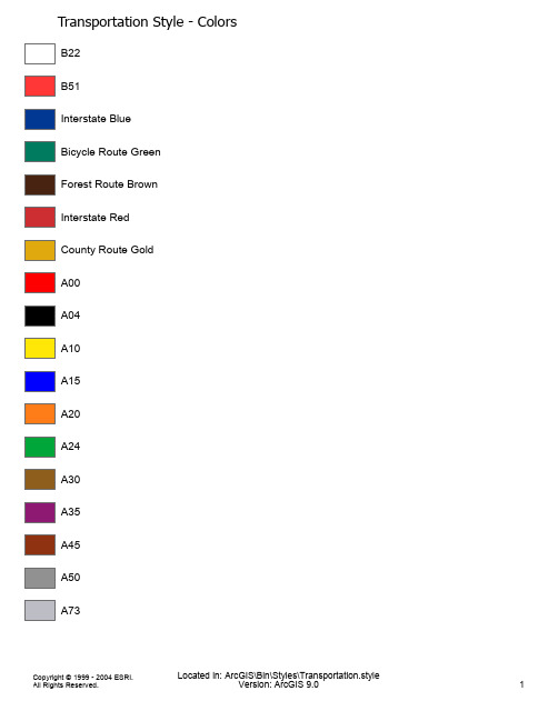
Transportation Style - ColorsB22B51Interstate BlueBicycle Route GreenForest Route BrownInterstate RedCounty Route GoldA00A04A10A15A20A24A30A35A45A50A73Transportation Style - Fill Symbols Construction Area OverlayTransportation Style - Labels55Shield 1 55Shield 2 55Shield 3 55Shield 4 55Shield 5 55Shield 6 55Shield 7 55Shield 8 55Shield 9 55Shield 10 55Shield 11 55Shield 12 55Shield 13 55Shield 14 55Shield 15 55Shield 16 55Shield 17 55Shield 18 55Shield 19 55Shield 20 55Shield 2155Shield 2255Shield 2355Shield 2455Shield 2555Shield 2655Shield 2755Shield 2855Shield 2955Shield 3055Shield 3155Shield 3255Shield 3355Shield 3455Shield 3555Shield 3655Shield 3755Shield 3855Shield 3955Shield 4055Shield 4155Shield 4255Shield 4355Loop 155County55State, Arizona55Speed Limit 155Speed Limit 255Shield 4455Shield 45A00 A01 A02 A03 A04 A05 A06 A07 A08A20A20A21A21A22A23A25A26A27A28A30A31A32A33A34A35A36A37 A38 A40 A41 A42 A43 A44 A45 A46A47A48A50A51A52A53A60A65A73B00B01B02B03B10B11B12B13B20B21B22B23B51þUS Route Independent Use ·State Route Independent Use ÿState Route%State Route WI"#Interstate Shield 1/US Route 10US Route 21US Route 3Ì2-Way7Bicycle RouteÍ3-WayÎ4-WayÏ5-WayA Advance Turn Arrow, Left AngleB Directional Arrow, Right B Directional Arrow, LeftC Directional Arrow, Up RightD Directional Arrow, UpE Directional Arrow, 2-Way AngledF Directional Arrow, 2-Way HorizontalG Directional Arrow, 2-Way DivergentH Directional Arrow, 2-Way Perpendicular ÕÒNo U TurnÚLane Turn Options (left)ÛLane Turn Options (right)òTrucks 1óBicyclesôDo Not Enter 1ûOne Way, AheadÿNo Right Turn on RedParkingCrosswalk Restricted Lane Ahead Bicycle Lane Ahead Center Lane Restriction Trucks 2Railroad Crossing 1 Left Turn Yield ExemptBridge Closed PicnickingCamping 1TOENDTemporary Stop4-WayAll Way Speed Limit 10 Speed Limit 15 Speed Limit 20 Speed Limit 25 Speed Limit 30 Speed Limit 35 Speed Limit 40 Speed Limit 45 Speed Limit 50 Speed Limit 55 Speed Limit 60 Speed Limit 652A Speed Limit 702@Speed Limit 75C E Speed Max 50 Min 30G I Reduced Speed AheadG J Speed Zone AheadG K Do Not PassG L Pass with CareG M Mandatory Movement (left) G N Mandatory Movement (right) G O Optional Movement (left)G P Optional Movement (right) G Q Keep Left (symbol)G R Keep Right (symbol)G S Slower Traffic Keep Right G T Keep Right G U Keep LeftG V Commercial Vehicles Excluded G W One Way, LeftG X One Way, RightG X Do Not Stop on TracksG Z No ParkingG[Do Not Block IntersectionG\Left Turn SignalG]Right Turn SignalG^No Turn on RedG_Keep Off Medianc g f No Right Turn (symbol)c h f No Left Turn (symbol)c j f No U-Turn (symbol)c i No TurnsMandatory Turn (left) Mandatory Turn (right)No Trucks (symbol)No VansNo BicyclesNo Parking (symbol)No Pedestrian Crossing (symbol) No Hitchhiking (symbol)Two Way Left Turn OnlyCross on Walk Signal Only Restricted Lane Ahead Restricted Lane EndsDo Not Enter 2No Motor VehiclesOne Way (enclosed in arrow)One Way (enclosed in arrow) Pedestrians ProhibitedNo Parking Anytime (left)No Parking Anytime (right)No Parking 8:30 am to 5:30 pmNo Parking Except Sundays and Holidays No Standing AnytimeNo Parking Loading ZoneReserved Parking (handicapped)No Parking Bike LaneNo Parking Bus StopTwo Hour Parking 8:30 am to 5:30 pm No Parking 8:30 am to 5:30 pmNo Parking Bus Stop (symbol)Tow-Away Zone (symbol)ÛÞTow-Away ZoneàâEmergency Parking OnlyäæNo Pedestrian CrossingèêNo HitchhikingîUse CrosswalkðòBicyclists Yield to Pedestrians ôöPush Button for Green Light "$Stop Here on Red(*Road Closed,.Road Closed to Thru Traffic 02Truck Route46Clean Up After Your Dog 89:;Turn to the Right89:<Turn to the Left89:=Curve to the Right 89:>Curve to the Left 89:?Reverse Turn89:²Reverse Turn89:@Reverse Curve89:A Reverse Curve89:D Cross Road89:E Side Road - Right89:F Side Road - Left89:G Side Road - Right (oblique) 89:H Side Road - Left (oblique) 89:I T-Intersection Ahead 89:K Stop Ahead89:L M N O Signal Ahead89:P Merge (right)89:Q Merge (left)89:R Pavement Width Transition 89:S Pavement Width Transition 89:T Added Lane (right)89:U Added Lane (left)89:V Road Narrows89:W Narrow Bridge89:X Narrow Bridge (symbol) 89:Y Divided Highway89:Z Divided Highway Ends 89:[Two Way Traffic89:\Steep Hill (trucks) 89:]Steep Hill (bicyclists) 89:^BUMP89:_DIP89:`Pavement Ends 89:a Soft Shoulder89:b Slippery When Wet (symbol) 89:c Rough Road89:d Low Shoulder89:e Shoulder Drop-Off89:f Hazardous Condition89:g Right Lane Ends89:h Left Lane Ends89:i Advance Railroad Warning 89:j Advance Railroad Warning 89:k Advance Railroad Warning 89:l Bicycle Crossing89:m Pedestrian (advance warning) 89:n Deer Crossing89:o Cattle Crossing89:p Kangaroo Crossing89:q Farm Machinery Crossing 89:r Equestrian Crossing 89:s Fire Station89:t Snowmobile (symbol) 89:u Handicapped Crossing 89:v Truck (symbol)89:w Pedestrian Crossing 89:x Double Arrow89:y Low Clearance89:z Dead End89:{No Outlet89:|Playground89:}Road Construction 500 Feet 89:¡Detour 1000 FT 89:¢Road Closed (street) 89:£Men Working89:¤Shoulder Work89:¥Survey Crew89:¦Blasting Zone 500 Feet 89:§Blasting Zone 1000 Feet 89:©Flaggerª«¬-One Direction (right)ª«¬®One Direction (left)ª«¬¯Two Directions°±Chevron Alignment (right)°²Chevron Alignment (left)³´µ¶Hill³´µ¸Slippery When Wet¹º»¼Railroad Crossing 2½¾¿Advisory Speed PlateÀÁÂÃAdvisory Exit Speed SignÄÅÆÇNo Passing ZoneÈÉÊË500 Feet (flagger)ÌÍÎÏEnd Blasting ZoneÐÑÒÓDetour Sign (right)ÐÑÒÔDetour Sign (left)ÕÖ×Detour Arrow Sign (right)ÕÖØDetour Arrow Sign (left)ÚDirectional Sign (right)ÚDirectional Sign (left)ÞàAdvance Turn Arrow (left)ÞáAdvance Turn Arrow (right)ÞâDirectional Arrow, Bicycle (right)ÞâDirectional Arrow, Bicycle (left)ÞäDirectional Arrow, BicycleÞåDirectional Arrow, BicycleÞæDirectional Arrow, BicycleÞçDirectional Arrow, BicycleÞèDirectional Arrow, BicycleÞéDirectional Arrow, BicycleÞêDirectional Arrow, BicycleÞëDirectional Arrow, BicycleÞíAdvance Turn Arrow (left)ÞìAdvance Turn Arrow (right)ÞîDirectional Arrow, Bicycle (left)ÞïDirectional Arrow, Bicycle (right)ñGore SignôöParking AreaûPark & RideTelephone with ArrowInterstate Shield 2Off-Interstate Business LoopU.S. Route Marker for Independent Use U.S. Route ShieldU.S. Route Marker for Guide Sign Use U.S. Route ShieldCounty Route MarkerState Route MarkerForest RouteJunction MarkerJunction Marker, Interstate Combination Junction SignCardinal Direction Marker - North Cardinal Direction Marker - East Cardinal Direction Marker - South Cardinal Direction Marker - West Cardinal Direction Marker - North (interstate) Cardinal Direction Marker - East (interstate) Cardinal Direction Marker - South (interstate) Cardinal Direction Marker - West (interstate) Alternate MarkerALT MarkerBypass MarkerBusiness Route MarkerDestination Sign (1)Destination Sign (2)Recreational and Cultural Interest Sign Roadside TableTelephonem Telephone 1/4 Mileo Hospitalp Camping 2q Trailer Campingr Access for Handicappeds Emergency Medical Servicest Gasu Diesel Gasv Propane Gasw Foodx Lodgingy Tourist Informationz Recreational Vehicle Sanitary Station {Library|Marina}Snow / Recreation ¡Trail¢Airport£Bus Station¤Train Station ¥Rest Area Gore§Police©Bike Route«Milepost Marker¬End Construction®End Road Work°Exit Only²Type 1 Object Marker ¶Type 2 Object Marker 2¶Type 2 Object Marker 1Supplemental Tourist Information Evacuation Route MarkerArea ClosedFallout ShelterSchool (advance)School CrossingSchool Bus Stop AheadSchoolSingle-Lane Pavement Marking Slow Children at PlayBlank Standard - OctagonBlank Standard - Equilateral Triangle Blank Standard - Vertical Rectangle Blank Standard - SquareBlank Standard - Diamond Blank Standard - Horizontal Rectangle Blank Standard - Interstate Shield Blank Standard - U.S. ShieldBlank Standard - PentagonBlank Standard - County Shield Blank Standard - CircleBlank Standard - National Forest Shield Blank Standard - Isosceles Triangle Do Not WalkWalk 2Don't WalkStreet LightStreet Light (green)Street Light (yellow)Street Light (red)ïâWalk 1÷ùWeigh StationF`Weight Limit 10 TonsG a Weight Limit 8-16 TonsÍÎWhen Flashing89:B Winding Road 289:C Winding Road 189:¨Worker©Wrong Way98:J Y-Intersection Ahead%&(YieldøúûýYield to Pedestrians Crossing ·}State Route CA 1ÿState Route CA 2Transportation - North ArrowsM Trans North 1G Trans North 2H Trans North 3。
导向仪使用说明
显示下一条 | 关闭萧瑟我还年轻,我渴望上路!导航•首页•日志•相册•音乐•收藏•博友•关于我日志liuwenzh 加博友关注他最新日志该作者的其他文章博主推荐相关日志随机阅读首页推荐全站仪的使用水平定向钻钻进轨迹和控制ECLIPSE月蚀导向仪的使用说明工作仪器2010-04-17 20:48:15 阅读554 评论2 字号:大中小订阅目录安全预防措施和警告事项........................................................................................................................ .. (5)概述........................................................................................................................ .. (7)接收器........................................................................................................................ .. (9)打开接收器........................................................................................................................ . (9)拨动式和触发式开关........................................................................................................................ .. (9)调整屏幕明暗对比........................................................................................................................ (10)主菜单........................................................................................................................ (10)Locate (定位)菜单........................................................................................................................进入定位模式........................................................................................................................ .. (12)离开定位模式并且回到主菜单 (12)(从定位屏幕)显示深度 (12)Set US(超声波测量值设定)菜单 (13)改变超声波测量值........................................................................................................................ .. (13)查看超声波测量设定值 (1)3Low Fre/High Fre(低频/高频设定)菜单 (14)改变频率设定值........................................................................................................................ .. (14)改变频率设定值........................................................................................................................ .. (14)Configure(设置)菜单........................................................................................................................ ..14变更遥感信号频道........................................................................................................................ .. (15)单点校准........................................................................................................................ (16)双点校准/ 地下校准........................................................................................................................ ..20变更斜度模式........................................................................................................................ .. (22)变更深度测量模式........................................................................................................................ .. (22)冷暗/正常屏幕........................................................................................................................远程显示器........................................................................................................................ . (23)键盘........................................................................................................................ . (23)打开远程显示器........................................................................................................................ . (23)扬声器和警告声........................................................................................................................ . (24)调整屏幕明暗对比........................................................................................................................ (24)主菜单........................................................................................................................ (25)Configure (设置)菜单........................................................................................................................ .26远程显示器屏幕........................................................................................................................ . (27)传感器........................................................................................................................ (31)Eclipse 传感器的类型........................................................................................................................ .. (31)倾角和面向角信息........................................................................................................................ (31)电池........................................................................................................................ . (32)温度更新信息和过热指标.......................................................................................................................32 DigiTrak® Eclipse® 用户手册3数字控制公司®目录(续)传感器(续)传感器启动及频率模式........................................................................................................................ (33)启动标准型Eclipse传感器 (33)启动双频Eclipse传感器 (33)睡眠模式(自动关闭)....................................................................................................................... . (34)传感器舱体要求........................................................................................................................ . (34)传感器的一般维护方法........................................................................................................................ (35)电池充电器........................................................................................................................ . (37)定位........................................................................................................................ (39)定位点(FLP 和RLP) 和定位线(LL) (40)定位程序........................................................................................................................ (41)目标指引(Target Steering® )功能 (45)决定可行的目标深度........................................................................................................................ . (45)输入目标深度........................................................................................................................ . (46)将接收器放置在目标位置.......................................................................................................................47指引到达目标........................................................................................................................ . (47)有线系统........................................................................................................................ .. (49)有线系统组件........................................................................................................................ . (50)操作有线系统所需要的非DCI 配件 (52)将电源供应器连接到电源和有线传感器上 (53)有线传感器接地........................................................................................................................ . (53)打开/关闭有线传感器........................................................................................................................ (54)校准有线传感器........................................................................................................................ . (54)使用有线系统定位........................................................................................................................ (54)检视传感器深度或预测深度 (54)检视有线系统电源状况........................................................................................................................ (55)使用有线系统执行目标指引功能 (55)故障检修........................................................................................................................ .. (57)附录........................................................................................................................ (59)钻杆每钻进10英尺所增加的深度英寸值 (60)钻杆每钻进15英尺所增加的深度英寸值 (61)斜度百分数换算为度数(0.1%倾角传感器或敏感倾角传感器) (62)度数换算为斜度百分数(0.1%倾角传感器) (63)根据前定位点和后定位点之间的距离计算深度 (64)安全预防措施和警告事项重要事项:所有操作人员必须阅读和了解以下的安全预防措施和警告事项,并且必须在使用DigiTrak® Eclipse® 定位系统之前复习本用户手册。
TrackPort 设备用户手册说明书
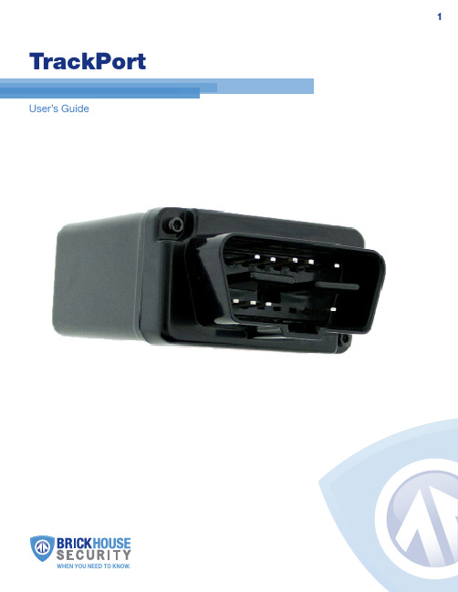
TrackPort User’s GuideWHEN YOU NEED TO KNOW.TrackPort Tape (Use to cover USB and SIM card as well as exposedLED lights)What’s InsideCellular SIM Card (Already indevice. If removal is necessary,use tweezers)LEDSPower IndicatorWill glow green when the device is receiving power.GPS/Cellular IndicatorThis indicator slowly blinks red, indicating the status of the device’s connection to the GPS and cellular networks. It runs on an 8-second cycle, first indicating GPS and then cellular.Cellular connection: At the beginning of the indicator cycle this LED will blink 1, 2, and 3 times as it begins communicating with the cellular network. 4 blinks at the beginning of the indicator cycle means the device has a cellular connection.Satellite connection: The second half of the indicator cycle indicatessatellite connection. It will blink once for no signal and twice to indicate a satellite connection.3211. Power Indicator2. GSM Status Indicator3. GPS Status Indicator4. Microphone (Disabled)5. Sim Card SlotGetting StartedYour TrackPort was activated before being shipped to you, and you should havereceived an email containing your default login information. If you did not receive your login information, please contact our support team at 800-654-7966 or by email at**********************************.Once securely plugged in, the device will begin reporting automatically once it hasregistered. It may take up to 20-30 minutes of driving for the TrackPort to register on the network for the first time.Tracking Your DeviceTo track your TrackPort, open a browser window and go to or go to Tracking on the drop down menu. Enter your username and password. The tracking page will appear, and the device’s last reported location will be centered on the map. If you have multiple devices on your account, the first 3 that were registered will be Tracking information is displayed using Google Earth Maps, so navigation is similar to what most people have grown used to in using internet-based mapping solutions. You can use the Navigation arrows and Zoom Bar to move around the map, or drag the map using your mouse and zoom using a click-wheel mouse.At the bottom of the pop-up window are the Zoom, Street View, and Live Tracker buttons.• Zoom will perform the same task as using the Zoom bar on the left side of the map; zooming in on the icon you have selected.• Street View will open up a separate window displaying Google’s Street View, if available.DashboardChangeMapViewThe BrickHouse shield icon will appear where a tracker transmitted most recently. Click on an icon to bring up a pop-up box. This will show your tracker’s name, the distance it has traveled on this trip, what direction it was moving in, speed, battery information, and start and stop locations. Start will display the beginning location of the current trip, and the time it was recorded. Stop will display the most recent location from the device, as well as the time it was reported.The More tab is not currently active. Future updates to the platform will utilize this tab. The GeoFence tab allows you to create quick geofences, based on the location you are currently viewing and route the device was following. Use the Circular GeoFence radio button to create a perimeter around the location you are clicked on. Use the Route GeoFence radio button to create a boundary that will follow the entire trip your device was on.Give the GeoFence a name in the GeoFence Name window, and (optional) add a short description in the Description box.Use the Action dropdown box to choose if you would like an alert created when the device enters the chosen area, exits the area, or both. Use the Radius box to choose how large the area will be. You can enter values below a mile as decimals. For example: A half-mile radius geofence would be entered as .5.When you are done, press the Create Geofence button to save.The Alerts tab will display current Geofence, Speed, Panic, or Motion alerts that have been triggered.The Video Links tab is not currently active. Future updates will take advantageof this tab.as well as allow you to see past locations. Using the drop-down boxes on the bottom right of the window, you can adjust how often your screen refreshes and how many locations will appear on the screen. The counter on the bottom left of the window displays how long it will be until your screen refreshes.The Calendar allows a user to choose from which dates information can display. Any date that has tracking information will be highlighted. Simply click on that date todisplay information. To choose multiple days, click on the Date Range button, input a start and end date, and press Search. Press the Current Date button to return to viewing the current day’s information. When searching by date, all locates generated in the chosen timeframe will display as breadcrumbs.Under the DISPLAY section you can see a list of all devices currently displayinginformation on the map. Click on the View/Change Device button to choose which of your devices will display on the map. This button only serves a purpose if there are multiple devices on your account.Breadcrumb Trail will display all locates, or breadcrumbs, generated on the date you currently have displayed, connected by a line. Click on any individual breadcrumb to see detailed information. The BrickHouse shield icon represents the start and stop of a trip, green circles mean the device was moving with the arrow indicating direction, and red octagons indicate stops.Click on the Street View button to open a Google Street View window from the most recent location of the device. This function will only work if Google Street View is available in that location.The Alerts section lets you manage what kinds of alerts your device will create and how you will be notified.Click the Geofence button to manage your geofences. The Geofence AlertConfiguration tab lets you choose when and where alerts will be sent. Select the device you would like to edit by checking the box next to it.• Highlight which days you would like to configure by clicking on each. You may choose to enter certain hours during which alerts will be active, or leave these fields blank to have them sent all the time.• Choose if duplicate alerts will not be created if the device stays inside or outside a geofence for a certain period of time using the slider bar.• Choose what icon will appear where a geofence alert was created using the Alert Image dropdown box.• Enter Email Address allows you to choose where alert notifications will be sent. Click on the + icon to add phone numbers you want to have texted.Using the DashboardCurrent DateIn the Create New Geofence tab you can create geofences around any area in different shapes. Navigate to the area on the map you would like to create a geofence. Click on the Circle, Polygon, or Route button. It is suggested that all geofences be in at least a .2 mile radius, or at least 1 city block around an area to allow for GPS drift.To create a circular geofence around an area, click on Circle and then click on the spot on the map you want to create your geofence around. Hold down the left mouse button and drag the cursor until your geofence is the size you want, and release the mouse button.The Polygon button allows you to create geofences in different shapes. Each point you click on will be a corner of your perimeter.You may also choose to enter a short description for your geofence.The Assign Geofence tab allows you to activate and deactivate geofences. Select a device from the dropdown menu to see what geofences are currently active. Clickon an Assigned Geofence to view and edit its configuration. Click the Remove link to deactivate a geofence. Hit Save once you have finished making changes.Click on the check box for any Available geofence to edit its configuration and press the Save button to implement it.The View Geofence tab allows you to view your geofences.Click the Speed button on the dashboard to set up speed alerts. Simply select your device and enter a speed which, when exceeded, will generate an alert. Choose the days and times you would like the alert to be active, if you would like duplicate alertsto be ignored, and enter an email address where you wish to receive your notifications. If you would prefer to receive alert notifications via text message, click on the + button and enter your phone information. Hit Save once you have finished configuring your alerts.The TrackPort does not take advantage of the BrickHouse Tracking platform’s Panic alert function.The Power Alert button is used for GPS devices with a battery. This device is hardwired and runs on your vehicle’s power, so disregard this button.You can run 4 different types of report, listed below. To run one, click on one of the buttons, choose the device you would like to run a report on from thedropdown box, choose the dates you would like to run your report on in the upper right corner, and press the magnifying glass search icon. You can export anygenerated reports to Microsoft Excel by clicking on the export button in the upper right corner of the window.Start/Stop reports will list trips between stopping points, with starting and ending locations, as well as speed information, trip duration, stop time, and thedistance traveled.The Alert History button will show you all alerts generated during the specified time and where they occurred.The Full History button includes individual locate information such as: location, time of transmission, battery life, speed, and distance from its previous locate.The Frequent Visits button will create a list of addresses that the device has reported from and show how many times the device reported from that spot.11 Changing Your PasswordTo change your password, click on the account name, which should appear in theupper right corner of the browser window. Once complete, just click on Quick View toreturn to your tracking page.To reach an FAQ, as well as other support materials for your device and the BrickHouseSecurity Tracking platform, click on the Help link in the upper right corner of the screen.Live support is available Monday through Friday between the hours of 9 am and 6 pmEST. at 1-800-654-7966.。
- 1、下载文档前请自行甄别文档内容的完整性,平台不提供额外的编辑、内容补充、找答案等附加服务。
- 2、"仅部分预览"的文档,不可在线预览部分如存在完整性等问题,可反馈申请退款(可完整预览的文档不适用该条件!)。
- 3、如文档侵犯您的权益,请联系客服反馈,我们会尽快为您处理(人工客服工作时间:9:00-18:30)。
动态跟踪应用功能及使用说明文件版本1.02014-10-9目录动态追踪软件使用说明 (3)1. 环境要求 (3)2. PTZ动态跟踪说明 (3)3. 功能列表 (6)4. 功能设置说明 (6)4.1主界面 (6)4.2 离线地图的下载与配置 (7)4.3 Map上显示报警对象位置和运动轨迹 (8)4.4手动选取目标进行跟踪: (9)4.5自动弹出云台控制窗口、自动跟踪报警对象: (9)4.6 视频监控、摄像机参数配置功能 (11)4.7 算法流程 (13)4.8程序调试 (13)4.9 可能出现问题 (15)5. 云台的技术要求 (16)6. 配置应用程序 (16)动态追踪软件使用说明1.环境要求MATE相应的硬件TriggerNG, Fireware版本为4.2+。
BVS VCA分析软件WINDOWS XP SP2/WINDOWS Server2003DOTNET framework 3.42.PTZ动态跟踪说明PTZ :在安防监控应用中是Pan/Tilt/Zoom 的简写,代表云台全方位(上下、左右)移动及镜头变倍、变焦控制。
动态PTZ 跟踪,可以使摄像机对自身的云台和变焦镜头进行自主PTZ驱动,并自动控制PTZ摄像机的进行云台全方位旋转和镜头缩放,针对被锁定的运动目标进行视觉导向的自动跟踪,以确保跟踪目标持续以放大特写画面出现在镜头中央,这样警卫人员可以更清晰的看到信息,同时还可以用于事后取证。
自动PTZ 跟踪模块弥补了固定摄像机监控视野狭窄的缺点,是完善的安全监控系统所必备的功能。
动态PTZ 跟踪监控系统具有目标分析功能,并配有高分辨率摄像机、大倍率光学变焦镜头和高转速云台,可以快速、准确的自动捕捉到可疑目标。
通过设置预置位动态PTZ 跟踪自动跟踪监控系统可以实现预置位扫描、自动巡航等功能,还能实现智能监控的诸多特殊要求。
另外动态PTZ 跟踪监控系统还具有外型美观、隐蔽性强等优点,因此十分适用于机场、广场、轨道交通、别墅区、政府行政单位、军区、博物馆等各类型场所的治安智能监控应用。
系统组成与技术分析动态PTZ 跟踪监控系统由智能视频分析服务器(负责智能分析与云台控制)与高速球型摄像机(负责跟踪目标)两部分组成。
动态PTZ跟踪:动态PTZ跟踪自动跟踪监控系统可以自主驱动云台和变焦镜头进行全方位旋转和镜头缩放,针对被锁定的运动目标进行视觉导向的自动跟踪,以确保跟踪目标持续以放大特写画面出现在镜头中央,这样警卫人员可以更清晰的看到信息,同时还可以用于事后取证。
动态PTZ跟踪动态PTZ跟踪自动跟踪监控系统弥补了固定摄像机监控视野狭窄的缺点,是完善的安全监控系统所必备的功能。
动态PTZ跟踪动态PTZ跟踪自动跟踪监控系统支持自动锁定跟踪触发后PTZ摄像机会自动拉近镜头,以确保入侵者在运动过程中始终以放大特写画面的方式出现在镜头中央。
同时,提供发现目标的地理位置坐标,能联动GIS地图,显示出动态的目标,而且同时将目标的类型(人、车),目标大小,距离远近,做出精确的判断。
对于某一个用于跟踪的PTZ摄像机,可以将其设定为与某个固定摄像机(或PTZ摄像机)相关联。
这样当被关联的固定摄像机检测到入侵(或被关联的PTZ摄像机在某个预置位上检测到入侵)时,将自动通知关联的PTZ摄像机跳转到关联预置位,并触发自主自动PTZ跟踪。
在进行自主自动PTZ跟踪时,既不需要通过预先设置预置位来定位目标,也不需要其他任何辅助摄像机或辅助传感器来参与检测跟踪。
当报警触发时,不再需要警卫人员通过手工来操纵PTZ控制键盘来寻找入侵者,PTZ摄像机在接收到报警事件时会自动锁定目标并触发自主跟踪,同时自动回传即时视频画面。
这样,安全警卫人员可以从容做出决策,而不会再像以往一样只根据检测到入侵的第一个场景做出盲目行动。
功能特点分析设置快捷方便用户在系统配置向导下,可以快速的配置应用场景,设置参照系。
完成屏幕向2D地理坐标的转换。
速度快精度高各类型的监控系统中都有很多的场所需要重点监控,当出现警情时需要及时发现、自动跟踪,因此跟踪速度就显得非常重要,更快的速度可以保证更短的时间扫描更多的预置点,有效提高监控利用率。
此外,系统实现了点击画面有效区域内任意点,系统将自动调整云台对焦到兴趣点,进行细致的观测,既减少用户的操作时间,同时还提高了操作的精度度。
报警联动功能强大报警是各类型监控项目中非常重要的环节,特别是智能监控,讲究的就是要求球机自动出辨别目标、分析目标并报警…..网络应用集成伴随着安防的智能化、数字化、网络化,动态PTZ跟踪自动跟踪监控系统(带网络功能)将是未来必然的需求,在多种监控方式整合的大平台里,若具备较好的网络资源,动态PTZ跟踪自动跟踪监控系统则是将智能分析功能和高速球集中管理、远程自动监控功能最好的结合,是未来监控发展的方向。
3.功能列表1. 利用RTSP实现视频监控,输出报警信息和报警截图;2. 利用GoogleMap在地图上显示报警对象位置和运动轨迹;3. 摄像机参数配置、绘制坐标系;4. 自动弹出云台控制窗口,自动跟踪报警对象,云台档位的配置、位置的初始化;5. 程序配置流程。
4.功能设置说明4.1主界面开始菜单:⑴连接设备:与设备建立连接,可接收设备发出的报警信息。
⑵断开连接:断开与设备建立的连接。
⑶云台控制:弹出摄像机实时预览画面,也可手动控制云台水平、垂直移动等。
⑷加载配置:加载在配置文件中设置的配置文件。
⑸视频管理:包括实时视频显示、报警日志、报警截图。
配置菜单:⑹配置分析设备:从数据库中选择视频分析设备。
⑺配置枪机:绘制参照系,配置摄像机参数。
⑻云台配置:包括设备配置、档位设置、摄像机初始化。
图1 智能视频应用平台(主界面)4.2 离线地图的下载与配置(1)【打开】全能电子地图下载器。
(2)点击矩形框,并在地图上【画出】需要下载的地图矩形,然后在【左边】的地图级别中勾选4-20级别的地图。
点击下载。
(3)在下载目录找到【googlemaps】文件夹,将文件夹复制到跟踪【maptile】4.3 Map上显示报警对象位置和运动轨迹图2 显示报警对象位置和运动轨迹4.4手动选取目标进行跟踪:(1)开始自动跟踪方法一:在画面上【按下鼠标】,然后手动【框选目标】,将【鼠标弹起】。
方法二:【双击】所要跟踪的目标。
(2)停止自动跟踪方法一:【单击】画面方法二:【点击】红色的大X(3)回预置位手动回预置位:点击右下角的【房子图标】的按钮自动回预置位:在跟踪完成后10秒,如果无任何操作,则会回预置位。
(4)手动云台操作点击左下角的【上】【下】【左】【右】【+】【-】按钮,即可对云台进行控制。
图3 云台控制窗口4.5自动弹出云台控制窗口、自动跟踪报警对象:⑴在云台控制窗口中可手动控制云台的上、下、左、右移动及镜头拉伸。
⑵IP:连接设备的IP地址;端口:设备端口号。
⑶用户名、密码:登录设备的用户名和密码。
⑷序列号:设备的序列号。
⑸硬盘个数、设备类型、报警输入个数、报警输出个数、模拟设备通道个数、起始通道号,根据实际填入。
(以上为注册时使用到的参数)⑹保存:保存新的参数配置,重新注册。
图4 DVR配置界面4.6 视频监控、摄像机参数配置功能4.6.1参数说明㈠摄像机参数⑴NTU*10:NTU 相当于十万分之一度。
⑵最大数量:参照坐标系的可用最大数量,默认为20。
⑶水平参考系尺寸:以“pixel”计算,即参照系图像的水平像素数。
⑷垂直参考系尺寸:以“pixel”计算,即参照系图像的纵向像素数。
⑸实际参考系数量:当前实际参照坐标系数组数量。
⑹相机高度:相机的架设高度,相对监控的地平面,单位为“米”。
⑺相机角度:相机角度-单位为“度”,正北方时为90度,正东方为0度。
⑻坐标系大小:水平参考系尺寸、垂直参考系尺寸对应的矩形大小。
⑼与相机距离:返回对象距离相机点的距离,单位为度量单位。
⑽对象世界坐标:对象框的世界坐标,以经纬度*NTU*10计算。
⑾相机世界坐标:相机或视点的世界坐标,以经纬度*NTU*10计算。
⑿与地平线交点:垂直的交点坐标。
⒀单位:度量单位,默认为“米”。
⒁球机GUID:标识当前控制的球机的ID号。
⒂设置摄像机位置:选中摄像机位置单选框,找到摄像机在GoogleMap上的位置,单击可设置摄像机摆放的位置。
⒃搜索:利用搜索功能,定位到当前地址对应在GoogleMap上的位置。
图5 摄像机参数配置界面㈡经纬度与距离转换⒄经纬度与距离转换参照值:包括A,B,C三点坐标。
由A,B,C三点的经纬度值算出AB,AC的距离,供经纬度与距离之间转换参考。
⒅经度单位:单位水平方向(单位米)上的经度值(单位NTU*10)。
⒆纬度单位:单位垂直方向(单位米)上的纬度值(单位NTU*10)。
图6 经纬度与距离转换4.7 算法流程4.8程序调试打开TrackParams.xml配置文件,调整参数,优化准确度!可通过ShowRect 来开关调试窗口解释:1.中心深蓝框:目标移到框内即停止移动和放缩,目标在框外则按照当前位置进行相应移动。
可由Centre控制2.最大紫色框:搜索窗,搜索目标的范围。
可由Padding控制。
3.10个小蓝色框:与目标相似的一些位置4.红色框:通过帧差检测到离目标上次最近的运动框,一般通过这个框来找目标,可通过帧差开关EnableFrameDiff来关闭。
4.曲线:历史运动轨迹6.圆圈和线:表示运动补偿方向,可通过EnableLogicCompensate来开关参数说明文档通过指定位置的TrackParams.xml文件来修改参数,参数包括四个部分:<TrackProfile><VideoSource> videosource接口<PTZControl>摄像头移动控制<DeviceInfo>设备信息<AlgorithmPara>算法参数下面对一些重要参数和问题做说明:<VideoSource>部分无法获取图像或在获取图像前跳出BUG时可检查下面参数•<VideoResourceType>视频源类型,默认必须设为:1•<IP> 默认为本机。
直接设为:127.0.0.1•<FrameNumber>通道号。
看视频在video source 通道号,默认最小为:1<DeviceInfo>部分目前没有应用到,不做修改<PTZControl>部分•重要参数与调整方法包括:•Centra:中心深蓝框边长的一半(单位:像素)CIFT分辨率一般为40-80•PositionControl:控制4方向和8方向,四方向值为4,八方向值为8•SpeedDelay*:速度延迟,目前用到1-4–SpeedDelay1:云台在平移时方向转换的延迟。