GSK218M990MA串口通讯软件说明书
广州数控GSK218M加工中心系统文档
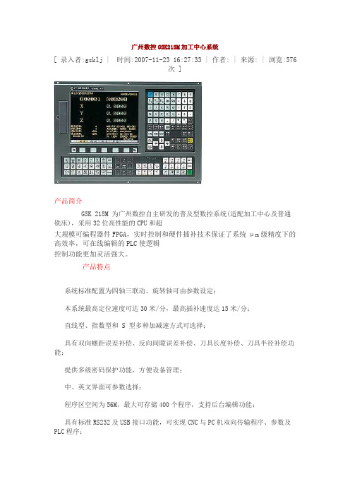
广州数控GSK218M加工中心系统[ 录入者:gsklj | 时间:2007-11-23 16:27:33 | 作者: | 来源: | 浏览:576次 ]产品简介GSK 218M 为广州数控自主研发的普及型数控系统(适配加工中心及普通铣床),采用32位高性能的CPU和超大规模可编程器件FPGA,实时控制和硬件插补技术保证了系统μm级精度下的高效率,可在线编辑的PLC使逻辑控制功能更加灵活强大。
产品特点系统标准配置为四轴三联动,旋转轴可由参数设定;本系统最高定位速度可达30米/分,最高插补速度达15米/分;直线型、指数型和 S 型多种加减速方式可选择;具有双向螺距误差补偿、反向间隙误差补偿、刀具长度补偿、刀具半径补偿功能;提供多级密码保护功能,方便设备管理;中、英文界面可参数选择;程序区空间为56M,最大可存储400个程序,支持后台编辑功能;具有标准RS232及USB接口功能,可实现CNC与PC机双向传输程序、参数及PLC程序;具有DNC控制功能,波特率可参数设定;内置PLC,实现机床的各种逻辑功能控制;梯形图可在线编辑、上传、下载; I/O 口可扩展(选配功能);标准梯图可适配斗笠式刀库和机械手刀库;手动干预返回功能使自动和手动方式灵活切换;手轮中断和单步中断功能可完成自动运行过程中的坐标系平移;程序再启动功能使公休或断刀后的断点处启动成为可能;背景编辑功能允许在自动运行时编辑程序;刚性攻丝和主轴跟随方式攻丝可由参数设定;三级自动换当功能,可由设定主轴转速随时切换变频输出电压;具有旋转、缩放、极坐标和多种固定循环功能;帮助菜单使操作者可脱离说明书随时在线查阅多种帮助选项。
广州数控GSK218M加工中心系统[ 录入者:gsklj | 时间:2007-11-23 16:27:33 | 作者: | 来源: | 浏览:577次 ]G代码及功能表技术规格。
GSK990MA系统连接参考图

GND XXX555...753 XXX544...175 XX44..31
主轴电机档
位控制部分
+24V XX55..64 XXX554...206 XX44..42 X4.0
+24V X3.6 XX33..24 XXX223...460 XX22..02
XXX+1112...4246V XXX001...460 X0.2 X0.0
C
限位、回零等开关检测信号部分
D
M3 电3机~
E
机
械
编码器
传 动
主轴
F 任选一种 主轴配制
机 械
主轴
编码器
传 动
G
1
2
机
械
传 动
主轴异步电机
机
械
传 动
主轴伺服电机
3
4
E
注:变频主轴报警信号输出 给XS23系统侧主轴信号接 口,见图号70/01
GSK990MA
部 件 名 称
F 总框架连线图
阶段标记
部件代号
990MA连接参考图
218M项目组全体职员祝您工作顺利!!
系统服务部热线:020-83969288(一号多线) 机床服务部热线:020-81790837/81786476 项目组服务热线: 020-81992188-8088/8306
2009年07月24号 更新
序号
代号
1
00
2
01
3
04
4
06
5
10
标记处数更改文件号 签 名 日期
设计
标准化
绘图
审核
总框架图
A
01
共 1 张 第 1 张
GSK990M系统操作教案

数控铣床GSK990M系统操作教案GSK990M是广州数控设备厂针对中国国情开发生产的操纵步进电机的经济型钻、镗、铣床及加工中心用数控系统,操纵电路采纳了高速微处置器,超大规模定制式集成电路芯片,多层印刷电路板,从而极大地提高了系统的靠得住性。
在操纵软件上,第一次将全功能数控系统的性能引入步进机操纵系统中,并针对步进机的特点增加了许多适合于步进电机的性能,使其发挥最正确的性能,从而使系统具有较高的性能价钱比。
CNC机床的一样操作用CNC机床加工零件时,第一要编制程序,然后用该程序操纵CNC机床。
(1) 第一,依照加工图纸编制零件加工程序。
说明书中“Ⅱ.编程篇”一篇中详细地介绍了编程方式。
(2) CNC读入程序后,把零件和刀具装在机床上,刀具按着程序运动,加工实际零件。
操作面板说明LCD/MDI面板GSK990M的LCD/MDI面板见图4.2.1.1显示性能键【POS】:位置。
【PRGRM】:程序。
【OFSET】:刀补。
【PARAM】:参数。
【DGNOS】:诊断。
【ALARM】:报警。
【GRAPH】:图形。
【SET】:设置。
【OPR/INDEX】:机床软操作面板/索引,两种显示画面由此键按键时切换显示。
当按这此显示性能键后,可直接显示对应的画面。
软菜单直接进入其中子目录。
注1:持续两次按同一显示功能键时,回到该显示的第一页。
性能软体键F4F3F5F1F2性能软体键是用于选择各类显示画面的菜单键。
每一主菜单下又细分为一些子菜单。
软体键对应要显示的内容显示在LCD的最下端。
在主菜单时,其性能同2.1.3的性能键。
最左端的软体键:从子菜单返回主菜单的初始状态。
最右端的软体键:选择同级菜单的其它菜单内容。
在其显示行上面提示左,右箭头提示在该菜单下只能按其键。
而无提示时键无效。
A) 主菜单:有2页,由最右边的软菜单键进行切换,每页有5 个菜单画面可选择.第一页[位置]: 按下其下面的软体键, LCDT显示此刻位置。
GSK980TD通讯软件说明书

目录第一章软件的系统要求_________________________ 2第二章软件功能 ______________________________ 3 2.1 文件的上传/下载操作 ____________________________________________ 3 2.2 CNC文件目录获取,文件的更名、删除操作 ___________________________ 3第三章使用说明 ______________________________ 4 3.1 硬件连接 ______________________________________________________ 4 3.2 软件界面 ______________________________________________________ 4 3.4 接收文件 ______________________________________________________ 8 3.5 CNC文件操作___________________________________________________ 9第一章软件的系统要求硬件:具有串口的通用PC机,串口通讯电缆 (三线制)操作系统:Microsoft Windows 98/2000/XP/2003第二章软件功能2.1 文件的上传/下载操作该软件可实现PC机与CNC之间的文件互传,可根据用户进行一次选择,实现多文件传输,并具备较高的通讯效率和可靠性。
2.2 CNC文件目录获取,文件的更名、删除操作在PC机可查询CNC系统上用户区的文件目录,获取各分区文件名和文件大小,以及可对用户区的文件进行更名和删除操作。
第三章使用说明3.1 硬件连接进行文件传输之前,用串口通讯电缆将PC机串口与980TD的通讯口连接起来。
确定连接无误且CNC正常运行后,即可运行本程序进行文件传输操作。
GSK210M系统说明书
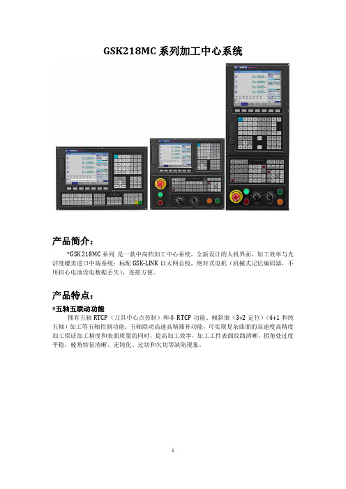
GSK218MC系列加工中心系统产品简介:*GSK 218MC系列是一款中高档加工中心系统,全新设计的人机界面,加工效率与光洁度媲美进口中端系统;标配GSK-LINK以太网总线,绝对式电机(机械式记忆编码器,不用担心电池没电数据丢失),连接方便。
产品特点:*五轴五联动功能拥有五轴RTCP(刀具中心点控制)和非RTCP功能、倾斜面(3+2定位)(4+1和纯五轴)加工等五轴控制功能;五轴联动高速高精插补功能,可实现复杂曲面的高速度高精度加工保证加工精度和表面质量的同时,提高加工效率,加工工件表面纹路清晰,拐角处过度平稳,棱角特征清晰、无钝化、过切和欠切等缺陷现象。
*高速高精功能采用高速插补技术,复杂曲面加工有效速度8m/min ,最佳加工速度4m/min ,预处理段数高达1000段,具有前瞻功能,速度快,精度高,光洁度好。
*便捷的调试方式总线配置在线刚性等级调试功能,进一步提升机床加工性能的机床刚性调节及参数优化功;不需要再单独一个个调试驱动的参数,简单化;具有优化功能,系统自己优化一组参数得以保持机床的高刚性。
总线配置在线圆度测试分析功能,圆度测试可模拟圆周切削运动圆并以此采集电机码盘位置信息来判断机床各伺服轴响应的同步性和响应速度。
*便捷的扩展功能I/O卡——扩展I/O点主轴卡——多主轴扩展,4路模拟电压,4路刚性攻丝伺服卡——多进给轴扩展,总线转脉冲采集卡——连接光栅等测量反馈装置模拟卡——可接收多路模拟输入、输出多路模拟电压*双驱校准、光栅检测功能具备读取光栅功能:光栅尺检测并调节横梁的水平度,保证加工时的水平精度具备精确停止插补及拐角平滑处理功能,有效防止拐角处发生过切现象具备自动校准双驱功能:通过从各电机的反馈,可以检测出2台电机间的同步误差,并进行同步误差补偿。
当同步误差超过设定值时报警,停止轴的移动,对同步误差值进行检查*适配自动对刀分中仪器,实现自动对刀分中功能进一步提升机床整体的自动化实用性,不需要再单独进行每把刀长度的校对,提高对工件分中的精确性,可增加自动对刀仪器,来实现自动对刀分中,从而提高整体的效率。
MAXIM MAX218 说明书

_______________General DescriptionThe MAX218 RS-232 transceiver is intended for battery-powered EIA/TIA-232E and V.28/V.24 communications interfaces that need two drivers and two receivers with minimum power consumption. It provides a wide +1.8V to +4.25V operating voltage range while maintaining true RS-232 and EIA/TIA-562 voltage levels. The MAX218 runs from two alkaline, NiCd, or NiMH cells without any form of voltage regulator.A shutdown mode reduces current consumption to 1µA, extending battery life in portable systems. While shut down, all receivers can remain active or can be disabled under logic control, permitting a system incor-porating the CMOS MAX218 to monitor external devices while in low-power shutdown mode.A guaranteed 120kbps data rate provides compatibility with popular software for communicating with personal computers. Three-state drivers are provided on all receiver outputs so that multiple receivers, generally of different interface standards, can be wire-ORed at the UART. The MAX218 is available in 20-pin DIP, SO, and SSOP packages.________________________ApplicationsBattery-Powered Equipment Computers Printers Peripherals Instruments Modems____________________________FeaturesBETTER THAN BIPOLAR!o Operates Directly from Two Alkaline, NiCd, or NiMH Cells o +1.8V to +4.25V Supply Voltage Range o 120kbps Data Rateo Low-Cost Surface-Mount Components o Meets EIA/TIA-232E Specifications o 1µA Low-Power Shutdown Modeo Both Receivers Active During Low-Power Shutdown o Three-State Receiver Outputs o Flow-Through Pinout o On-Board DC-DC Converterso 20-Pin SSOP, Wide SO, or DIP Packages______________Ordering Information*Contact factory for dice specifications.MAX2181.8V to 4.25V-Powered,True RS-232 Dual Transceiver________________________________________________________________Maxim Integrated Products1__________________Pin Configuration__________Typical Operating CircuitCall toll free 1-800-998-8800 for free samples or literature.19-0246; Rev 1; 7/95M A X 2181.8V to 4.25V-Powered,True RS-232 Dual Transceiver 2_______________________________________________________________________________________ABSOLUTE MAXIMUM RATINGSELECTRICAL CHARACTERISTICS(Circuit of Figure 1, V CC = 1.8V to 4.25V, C1 = 0.47µF, C2 = C3 = C4 = 1µF, L1 = 15µH, T A = T MIN to T MAX , unless otherwise noted.Typical values are at V= 3.0V, T = +25°C.)Stresses beyond those listed under “Absolute Maximum Ratings” may cause permanent damage to the device. These are stress ratings only, and functional operation of the device at these or any other conditions beyond those indicated in the operational sections of the specifications is not implied. Exposure to absolute maximum rating conditions for extended periods may affect device reliability.Supply VoltagesV CC ....................................................................-0.3V to +4.6V V+..........................................................(V CC - 0.3V) to +7.5V V-.......................................................................+0.3V to -7.4V V CC to V-..........................................................................+12V LX ................................................................-0.3V to (1V + V+)Input VoltagesT_IN, EN, S —H —D —N –.................................................-0.3V to +7V R_IN.................................................................................±25V Output VoltagesT_OUT.............................................................................±15V)R_OUT....................................................-0.3V to (V CC + 0.3V)Short-Circuit Duration, R_OUT, T_OUT to GND .......Continuous Continuous Power Dissipation (T A = +70°C)Plastic DIP (derate 11.11mW/°C above +70°C)..........889mW Wide SO (derate 10.00mW/°C above +70°C)..............800mW SSOP (derate 8.00mW/°C above +70°C)...................640mW Operating Temperature RangesMAX218C_ P.....................................................0°C to +70°C MAX218E_ P...................................................-40°C to +85°C Storage Temperature Range ...........................-65°C to +150°C Lead Temperature (soldering, 10sec) ...........................+300°CNote 1:Entire supply current for the circuit of Figure 1.MAX2181.8V to 4.25V-Powered,True RS-232 Dual Transceiver_______________________________________________________________________________________3TIMING CHARACTERISTICS(Circuit of Figure 1, V CC = 1.8V to 4.25V, C1 = 0.47µF, C2 = C3 = C4 = 1µF, L1 = 15µH, T A = T MIN to T MAX , unless otherwise noted.Typical values are at V CC = 3.0V, T A = +25°C.)______________________________________________________________Pin DescriptionReceiver InputsR2IN, R1IN 11, 12Transmitter Outputs; swing between V+ and V-.T2OUT, T1OUT13, 14Negative Supply generated on-boardV-15Terminals for Negative Charge-Pump Capacitor C1-, C1+16, 18Positive Supply generated on-boardV+19Ground. Connect all GND pins to ground.GND 5, 17, 20Supply Voltage Input; 1.8V to 4.25V. Bypass to GND with at least 1µF. See Capacitor Selection section.V CC 6Transmitter InputsT1IN, T2IN 7, 8Receiver Outputs; swing between GND and V CC.R1OUT, R2OUT 9, 10Receiver Output Enable Control. Connect to V CC for normal operation. Connect to GND to force the receiver outputs into high-Z state.EN 4Shutdown Control. Connect to V CC for normal operation. Connect to GND to shut down the power supply and to disable the drivers. Receiver status is not changed by this control.S —H —D —N–3PIN Not internally connectedN.C.2Inductor/Diode Connection Point LX 1FUNCTIONNAMEM A X 2181.8V to 4.25V-Powered,True RS-232 Dual Transceiver 4_______________________________________________________________________________________8-8TRANSMITTER OUTPUT VOLTAGE vs. LOAD CAPACITANCE AT 120kbpsLOAD CAPACITANCE (pF)T R A N S M I T T E R O U T P U T V O L T A G E (V )30000-2-6-41000200050006424000120SLEW RATE vs.TRANSMITTER CAPACITANCELOAD CAPACITANCE (pF)S L E W R A T E (V /µs )300042010002000500010864000__________________________________________Typical Operating Characteristics(Circuit of Figure 1, V CC = 1.8V, all transmitter outputs loaded with 3k Ω, T A = +25°C, unless otherwise noted.)12014001.8SUPPLY CURRENT vs. SUPPLY VOLTAGESUPPLY VOLTAGE (V)S U P P L Y C U R R E N T (m A )3.6604020 2.43.0801004.210020TRANSMITTING SUPPLY CURRENTvs. LOAD CAPACITANCELOAD CAPACITANCE (pF)S U P P L Y C U R R EN T (m A )30006050304010002000500090807040002V/divTIME TO EXIT SHUTDOWN (ONE TRANSMITTER HIGH, ONE TRANSMITTER LOW)100µs/divMAX2181.8V to 4.25V-Powered,True RS-232 Dual Transceiver_______________________________________________________________________________________5_______________Detailed DescriptionThe MAX218 line driver/receiver is intended for battery-powered EIA/TIA-232 and V.28/V.24 communications interfaces that require two drivers and two receivers.The operating voltage extends from 1.8V to 4.25V, yet the device maintains true RS-232 and EIA/TIA-562transmitter output voltage levels. This wide supply volt-age range permits direct operation from a variety of batteries without the need for a voltage regulator. For example, the MAX218 can be run directly from a single lithium cell or a pair of alkaline cells. It can also be run directly from two NiCd or NiMH cells from full-charge voltage down to the normal 0.9V/cell end-of-life point.The 4.25V maximum supply voltage allows the two rechargeable cells to be trickle- or fast-charged while driving the MAX218.The circuit comprises three sections: power supply,transmitters, and receivers. The power-supply section converts the supplied input voltage to 6.5V, providing the voltages necessary for the drivers to meet true RS-232levels. External components are small and inexpensive.The transmitters and receivers are guaranteed to oper-ate at 120kbps data rates, providing compatibility with LapLink™ and other high-speed communications soft-ware. A shutdown mode extends battery life by reduc-ing supply current to 0.04µA. While shut down, all receivers can either remain active or be disabled under logic control. With this feature, the MAX218 can be in low-power shutdown mode and still monitor activity on external devices. Three-state drivers are provided on both receiver outputs.Switch-Mode Power SupplyThe switch-mode power supply uses a single inductor with one diode and three small capacitors to generate ±6.5V from an input voltage in the 1.8V to 4.25V range.Inductor SelectionUse a 15µH inductor with a saturation current rating of at least 350mA and less than 1Ωresistance. Table 1 lists suppliers of inductors that meet the 15µH/350mA/1Ωspecifications.Diode SelectionKey diode specifications are fast recovery time (<10ns),average current rating (>100mA), and peak current rat-ing (>350mA). Inexpensive fast silicon diodes, such as the 1N6050, are generally recommended. More expen-sive Schottky diodes improve efficiency and give slightly better performance at very low V CC voltages. Table 1lists suppliers of both surface-mount and through-hole diodes. 1N914s are usually satisfactory, but specifica-tions and performance vary widely with different manu-facturers.Capacitor SelectionUse capacitors with values at least as indicated in Figure 1. Capacitor C2 determines the ripple on V+,but not the absolute voltage. Capacitors C1 and C3determine both the ripple and the absolute voltage of V-. Bypass V CC to GND with at least 1µF (C4) placed close to pins 5 and 6. If the V CC line is not bypassed elsewhere (e.g., at the power supply), increase C4 to 4.7µF.You may use ceramic or polarized capacitors in all locations. If you use polarized capacitors, tantalum types are preferred because of the high operating fre-quency of the power supplies (about 250kHz). If alu-minum electrolytics are used, higher capacitance val-ues may be required.™ LapLink is a trademark of Traveling Software, Inc.Figure 1.Single-Supply OperationM A X 2181.8V to 4.25V-Powered,True RS-232 Dual Transceiver 6_______________________________________________________________________________________RS-232 DriversThe two drivers are identical, and deliver EIA/TIA-232E and EIA/TIA-562 output voltage levels when V DD is between 1.8V and 4.25V. The transmitters drive up to 3k Ωin parallel with 1000pF at up to 120kbps. Connect unused driver inputs to either GND or V CC . Disable the drivers by taking S —H —D —N –low. The transmitter outputs areforced into a high-impedance state when S —H —D —N –is low.RS-232 ReceiversThe two receivers are identical, and accept both EIA/TIA-232E and EIA/TIA-562 input signals. The CMOS receiver outputs swing rail-to-rail. When EN is high, the receivers are active regardless of the state of S —H —D —N –. When EN is low, the receiver outputs are put into a high-impedance state. This allows two RS-232ports (or two ports of different types) to be wired-ORed at the UART.Operating ModesS —H —D —N –and EN determine the MAX218’s mode of opera-tion, as shown in Table 2.Table 2. Operating ModesShutdown When S —H —D —N –is low, the power supplies are disabled and the transmitters are put into a high-impedance state.Receiver operation is not affected by taking S —H —D —N –low.Power consumption is dramatically reduced in shutdown mode. Supply current is minimized when the receiver inputs are static in any of three states: floating (ground),GND, or V CC .__________Applications InformationOperation from Regulated/UnregulatedDual System Power Supplies The MAX218 is intended for use with three different power-supply sources: it can be powered directly from a battery, from a 3.0V or 3.3V power supply, or simulta-neously from both. Figure 1 shows the single-supply configuration. Figure 2 shows the circuit for operation from both a 3V supply and a raw battery supply—an ideal configuration where a regulated 3V supply is being derived from two cells. In this application, the MAX218’s logic levels remain appropriate for interface with 3V logic, yet most of the power for the MAX218 is drawn directly from the battery, without suffering the efficiency losses of the DC-DC converter. This pro-longs battery life.Bypass the input supplies with 0.1µF at V CC (C4) and at least 1µF at the inductor (C5). Increase C5 to 4.7µF if the power supply has no other bypass capacitor con-nected to it.Table 1. Suggested Component SuppliersMAX2181.8V to 4.25V-Powered,True RS-232 Dual Transceiver_______________________________________________________________________________________7Low-Power OperationThe following suggestions will help you get maximum life out of your batteries.Shut the MAX218 down when it is not being used for transmission. The receivers can remain active when the MAX218 is shut down, to alert your system to exter-nal activity.Transmit at the highest practical data rate. Although this raises the supply current while transmission is in progress, the transmission will be over sooner. As long as the MAX218 is shut down as soon as each transmis-sion ends, this practice will save energy.Operate your whole system from the raw battery volt-age rather than suffer the losses of a regulator or DC-DC converter. If this is not possible, but your system is powered from two cells and employs a 3V DC-DC con-verter to generate the main logic supply, use the circuit of Figure 2. This circuit draws most of the MAX218’spower straight from the battery, but still provides logic-level compatibility with the 3V logic.Keep communications cables short to minimize capaci-tive loading. Lowering the capacitive loading on the transmitter outputs reduces the MAX218’s power con-sumption. Using short, low-capacitance cable also helps transmission at the highest data rates.Keep the S —H —D —N –pin low while power is being applied tothe MAX218, and take S —H —D —N –high only after V CC has risen above about 1.5V. This avoids active operation at very low voltages, where currents of up to 150mA can be drawn. This is especially important with systems pow-ered from rechargeable cells;if S —H —D —N –is high while the cells are being trickle charged from a deep discharge,the MAX218 could draw a significant amount of the charging current until the battery voltage rises above 1.5V.Pin Configuration ChangeThe Pin Configuration shows pin 2 as N.C. (no con-nect). Early samples had a bypass capacitor for the internal reference connected to pin 2, which was labeled REF. This bypass capacitor proved to be unnecessary and the connection has been omitted. Pin 2 may now be connected to ground, left open, or bypassed to GND with a capacitor.EIA/TIA-232E and_____________EIA/TIA-562 StandardsRS-232 circuits consume much of their power because the EIA/TIA-232E standard demands that the transmit-ters deliver at least 5V to receivers with impedances that can be as low as 3k Ω. For applications where power consumption is critical, the EIA/TIA-562 standard provides an alternative.EIA/TIA-562 transmitter output voltage levels need only reach ±3.7V, and because they have to drive the same 3k Ωreceiver loads, the total power consumption is con-siderably reduced. Since the EIA/TIA-232E and EIA/TIA-562 receiver input voltage thresholds are the same, interoperability between EIA/TIA-232E and EIA/TIA-562 devices is guaranteed. Maxim’s MAX560and MAX561 are EIA/TIA-562 transceivers that operate on a single supply from 3.0V to 3.6V, and the MAX562transceiver operates from 2.7V to 5.25V while produc-ing EIA/TIA-562 levels.Figure 2.Operating from Unregulated and Regulated SuppliesMaxim cannot assume responsibility for use of any circuitry other than circuitry entirely embodied in a Maxim product. No circuit patent licenses are implied. Maxim reserves the right to change the circuitry and specifications without notice at any time.8___________________Maxim Integrated Products, 120 San Gabriel Drive, Sunnyvale, CA 94086 (408) 737-7600©1995 Maxim Integrated ProductsPrinted USAis a registered trademark of Maxim Integrated Products.M A X 2181.8V to 4.25V-Powered,True RS-232 Dual Transceiver ___________________Chip TopographyTRANSISTOR COUNT: 571SUBSTRATE CONNECTED TO GNDC1+GND T1OUT SHDN ENT2OUTGND T1INLXV+R2IN R1OUTT2IN R2OUT0.101" (2.565mm)0.122" (3.099mm)R1IN C1-V-GNDVCC______3V-Powered EIA/TIA-232 and EIA/TIA-562 Transceivers from Maxim。
GSK218M机床调试

1. 请严格按下表连接:
地 址 信号接口
X000.0
XS43
X000.1
XS43
X000.2
XS43
X000.3
XS43
X000.4
XS43
X000.5
XS43
2. 修改下表参数
地址 定 义
接口脚号 1 14 2 15 17 5
定义 X 轴正向行程限位信号 X 轴负向行程限位信号 Y 轴正向行程限位信号 Y 轴负向行程限位信号 Z 轴正向行程限位信号 Z 轴负向行程限位信号
4.5 有关轴的设置
如果机床移动方向与位移指令要求方向不一致,可修改系统参数 No.003 的 Bit1~Biit5 系统参数号
003
DIR5 DIR4 DIRZ DIRY DIRX
DIRX =1: X轴进给方向。
=0: X轴进给方向取反。
DIRY =1: Y轴进给方向。
=0: Y轴进给方向取反。
DIRZ =1: Z轴进给方向。
4.3.6 是否有外部编辑锁及外部操作面板锁
z 相关信号 LEDT:外部编辑锁信号,当信号为 1 时,程序可编辑,与系统上的程序开关功能相同; LSYS:外部操作面板锁信号,当信号为 1 时,机床操作所有按键被锁住。
z 信号诊断
参数诊断(系统侧输入状态)
状态地址 脚号 X3.0=外部编辑锁(常开触点) X3.1=外部操作面板锁(常开触点)
返回GSK资料库
4 机床调试
本章介绍 GSK218M 系统首次通电时的试运行方法及其步骤,按下面的操作步骤进行调 试后,可以进行相应的机床操作。
4.1 调试准备
GSK218M 的调试可按下列步骤进行: z 系统的连接:正确的连接是系统调试顺利进行的基础; z PLC 调试: 使系统安全功能生效(如急停、硬限位等)以及操作功能生效; z 驱动器参数设定:设置电机型号参数,控制方式等的设定; z 系统参数设定:设置控制参数、速度参数等; z 数据备份:系统调试完毕后,进行数据备份如参数备份、补偿数据备份、PLC 程序 的备份等。
GSK218mc调试

GSK-218MC(总线)调试流程1:上电后,首先对三轴驱动参数初始化,解除ERR-28号报警。
初始化方法:在EE-DEF菜单下按回车键即可。
2:写入驱动相关参数:PA8=100.,在EE-SET菜单下保存。
3:写入主轴驱动参数:PA4=3,PA19=70,PA122=1,PA28=1在EE-SET菜单下保存4:机床总电断电。
5:系统上电6:插入U盘,MDI方式,按【设置】键,将参数保护开关=1,写入密码ADMIN. 7:按【数据】软菜单,再按【数据输入】,选择相应菜单,分别复制U盘中的梯图、系统参数、程序。
其中系统参数输入后,按【数据还原】才能生效。
注意:U盘中有两个梯图为圆盘梯图,Ladchi00.txt为plc信号说明,为斗笠刀库梯图,Ladchi01.txt为plc信号说明。
四个文件都传入系统。
用参数P53#0选择要运行的梯图,P53#0=0运行圆盘梯图,P53#0=1运行斗笠梯图。
8:电机零点的设置:按有关说明设定.9:电子齿轮比设定。
(1)齿轮比可在驱动PA12/PA13参数里设定,也可在系统参数(数参)P160-162(分子),P165-P167(分母)里设定。
计算方法如下:131072/丝杠螺距x1000. (机械传动比为1:1)。
下面根据不同机型参数设定如下:螺距10mm,机械传动比1:1,电子齿轮比为8192/625螺距12mm,机械传动比1:1,电子齿轮比为,4096/375螺距6mm,机械传动比1:1,电子齿轮比为,8192/37510:有关PLC参数的设定。
K0.0=1 PLC参数允许修改(刀库数据,存储器,定时器)K1.0=1 带刀库K5.0=1 带外接手轮K7.5=0 带外接急停K9.1=1油位检测有效K9.5=1 冷却电机过载有效K9.3=1刀库电机过载有效D100=16/20/24 总刀位数C100=16/20/24 总刀位数其中圆盘刀库时设定:K10.5=1刀库计数开关选择常闭型。
- 1、下载文档前请自行甄别文档内容的完整性,平台不提供额外的编辑、内容补充、找答案等附加服务。
- 2、"仅部分预览"的文档,不可在线预览部分如存在完整性等问题,可反馈申请退款(可完整预览的文档不适用该条件!)。
- 3、如文档侵犯您的权益,请联系客服反馈,我们会尽快为您处理(人工客服工作时间:9:00-18:30)。
串口通讯软件说明书
串口通讯软件为Windows界面,用于PC端向CNC端发送文件、接收文件,或者进行DNC加工。
该软件可运行于Win98、WinMe、WinXP及Win2K。
1 程序启动:
直接运行GSK Comm .exe程序。
程序启动后界面如下:
2 功能介紹:
1.文件菜单
文件菜单里包括新建、打开和保存程序文件,打印和打印设置,最近打开的文件列
表等功能。
2.编辑菜单
编辑菜单包括剪切、复制、粘贴、撤消、查找、替换等功能。
3.串口菜单
主要是串口的打开和设置。
4.传输方式菜单
包括DNC传输方式、文件发送传输方式、文件接收传输方式。
5.查看菜单
工具栏和状态栏的显示和隐藏。
6.帮助菜单
本软件的版本信息。
3 软件使用:
1. DNC传输方式
注:需要将系统I/O通道设为0
1) 通过文件菜单的“打开”按钮或者工具栏的打开按钮打开程序文
件,有必要的话可以利用本软件再进一步编辑。
2) 打开并设置好串口,如上图所示,选择适用于GSK218M,系统默认的
DNC波特率是38400,可通过参数重新设置(具体参考218M系统操作
说明书)。
218M系统设置为数据位8位,停止位0位,无奇偶校验。
3) 第一和第二步顺序可相互交换,不影响接下来的传输和加工;但接下去的
步骤必须按顺序操作,否则会影响传输和加工效果。
4) CNC端和机床准备好了之后,按下CNC面板上的按钮。
5) 打开传输方式菜单的“DNC”菜单项或者是按下工具栏的
DNC传输按钮,找到程序开始传送数据。
6) 当“发送字节”数停止时,按下CNC面板上的键接收数据,然后
再按下CNC面板上的按钮开始加工。
7) 接下去的可以正常加工的方式进行操作。
8)传输开始后,本程序会显示出传输的情况,包括传输的文件名,传输的字
节数,传输的行数,传输所用的时间和传输的速度(字节/秒);界面如下:
此时除结束传输之外,请不要对本软件进行其它的操作。
加工完后按键
取消操作。
2. 发送文件传输方式
1) 进入设置页面中的数据界面,根据传输内容通过方向键红色标志移动到
“数据输入”下的相应方框内,按回车键。
2) 打开并设置好串口,波特率只能是115200,数据位、停止位和奇偶校验
与DNC传输时相同。
3)打开传输方式菜单的“发送文件”菜单项或者是按下工具栏的
发送文件按钮,系统将会弹出以下对话框:
4)选择“添加文件”按钮,出现“选择分区”的对话框:
程序文件只能发送到“用户分区”,而系统配置文件和备份文件则只能发
送到系统分区,否则系统将不能识别该文件。
发送系统配置文件和备份文
件需要有系统厂商或者机床厂商的权限,可在CNC端设置页面中的“密码”设置
页面输入相关的密码设置。
5) 选择分区之后将会出现“打开文件”对话框,按住Shift或者Ctrl键便能选
择多个文件;最多可以选择399个文件。
6) 选择好文件之后点击“打开”按钮,返回“发送文件”对话框。
7) 发送到用户分区的程序文件名必须是以字母“O”开头,后带5位以内(包
括五位)数字的文件名。
否则程序会弹出以下对话框提示你更改文件名:
8)返回“发送文件”对话框后,点击“发送”按钮,文件开始发送并出现如下
对话框:
9)传输完毕。
注:1、系统在DNC方式时不能发送文件。
2、当系统处于工作状态时进行程序的传输操作,会影响系统当前的正常工
作。
3. 接收文件传输方式
1) 进入设置页面中的数据界面,根据传输内容通过方向键红色标志移动到
“数据输出”下的相应方框内,按回车键。
2)打开并设置好串口,波特率只能是115200,数据位、停止位和奇偶校验
与DNC传输时相同,不能改变。
3)打开传输方式菜单的“接收文件”菜单项或者是按下工具栏的
接收文件按钮,系统将会弹出以下对话框:
4)点击“获取目录”按钮可获取CNC中的文件列表。
5)选择所要传输的文件,按住Shift或者Ctrl键便能选择多个文件。
6)点出“开始接收”按钮,选择接收文件的存放地址,进行传输,出现以下对
话框:
7)传输完毕。
注:1、系统在DNC方式时不能接收文件。
2、当系统处于工作状态时进行程序的传输操作,会影响系统当前的正常工作。