RG-ePortal网络访问门户系统
RG-ePortal_1.43(p3)_Build20140425系统操作手册(V1.0)
网关认证模式:不启用时,为普通模式,即 ePortal 普通版,可以配合 3.14 及以上版本使 用;启用时,为网关版,即 eportal 定制版,可以配合 3.30 及以上版本使用,需要部署 RG-ACE。外网服务指的是访问网关外的网络,内网服务指的是访问网关内的网络,服务 的名称需要与 RADIUS 服务器中用户模板的套餐规则里配置的服务相对应。网关模式下, 用户可以随时选择接入内网或者外网。 RADIUS 服务器节点的 IP 地址:如果 RADIUS 服务器是单机,请将本栏留空,不需要配 置;如果 RADIUS 服务器是群集,请将 RADIUS 服务器群集中的每台节点的 IP 地址填入 本栏中,填写不分顺序。
有时为了提高 RG-ePortal 软件的性能和可靠性,我们会对软件做一些改动,这样可能产生软件配置与用户手册在某 些细节不一致的情况。对这种情况,我们会尽量更新一些资料(如手册、光盘)来弥补这些差异,但有时仍有可能 造成不一致,希望您能够谅解。
虽然在编写本手册时我们非常认真谨慎,并认为手册中所提供的信息是正确可靠的,然而难免会有错误和疏漏之处, 请您多加包涵并热忱欢迎您的指正。同时,由于我们无法避免用户对本手册可能造成的误解,因此如果您在安装、 使用 RG-ePortal 的过程中发现什么问题,请拨打我们的客服热线。对于可能由于用户的不当操作造成的损害,我们 深表遗憾,但无法对这些损害进行赔偿。
注意页面上的“*”号,本系统中所有标有此星号的数据项都是必须填写的。 您可以随时查看目前使用的 RG-ePortal 的版本。点击主页面右上方的“关于”按钮,会弹出相 关 RG-ePortal 系统版本名称,版本号,创建日期等相关信息。
5
系统配置
5 系统配置
锐捷 RG-EW系列路由器Web配置指南说明书
Ruijie Reyee RG-EW Series Routers Web-Based Configuration GuideCopyright StatementRuijie Networks©2021Ruijie Networks reserves all copyrights of this document. Any reproduction, excerption, backup, modification, transmission, translation or commercial use of this document or any portion of this document, in any form or by any means, without the prior written consent of Ruijie Networks is prohibited.Exemption StatementThis document is provided “as is”. The contents of this document are subject to change without any notice. Please obtain the latest information through the Ruijie Networks website. Ruijie Networks endeavors to ensure content accuracy and will not shoulder any responsibility for losses and damages caused due to content omissions, inaccuracies or errors.PrefaceThank you for using our products.AudienceThis manual is intended for:●Network engineers●Technical support and servicing engineers●Network administratorsObtaining TechnicalAssistance●Ruijie Networks Website: https:///●Technical Support Website: https:///support ●Case Portal: https://●Community: https://●Technical Support Email: *****************************●Skype: *****************************Related DocumentsConventionsThis manual uses the following conventions:Configuration Guide Overview 1 OvervieweWeb is a Web-based network management system that manages or configures devices. You can access eWeb via browsers such as Google Chrome.Web-based management involves a Web server and a Web client. The Web server is integrated in a device, and is used to receive and process requests from the client, and return processing results to the client. The Web client usually refers to a browser, such as Google Chrome IE, or Firefox.1.1 ConventionsIn this document, texts in bold are names of buttons (for example, OK) or other graphical user interface (GUI) elements (for example, DHCP Security).2 Configuration Guide2.1 PreparationScenarioAs shown in the figure below, an administrator can access the device from a browser and configure the device through the eWeb management system.Figure 2-1-1 Data Exchange PrincipleDeliver or requestcommandsthrough AJAX.Administrator Return dataWebserviceDeviceDeployment↘Configuration Environment RequirementsClient requirements:●An administrator can log into the eWeb management system from a Web browser to manage devices. The client refersto a PC or some other mobile endpoints such as laptops or tablets.●Google Chrome, Firefox, IE10.0 and later versions, and some Chromium-based browsers (such as 360 ExtremeExplorer) are supported. Exceptions such as garble or format error may occur if an unsupported browser is used.●1024 x 768 or a higher resolution is recommended. If other resolutions are used, the page fonts and formats may not bealigned and the GUI is less artistic, or other exceptions may occur.●The client IP address is set in the same LAN network as the device IP address, such as 192.168.120.X. The subnetmask is 255.255.255.0. The default management address of the device is 192.168.120.1. Alternatively, you can set the IP assignment mode to Obtain an IP address automatically.Server requirements:●You can log into the eWeb management system through a LAN port or from Ruijie Cloud on an external network.●The device is enabled with Web service (enabled by default).The device is enabled with login authentication (enabled by default).To log into the eWeb management system, open the Google Chrome browser, and enter 192.168.120.1 into the address bar, and press Enter .Figure 2-1-2 Login PageEnter the password and click Login .2.2 Network SetupYou will enter the Network Setup page without login at initial setup.2.2.1 Discover DeviceThe page displays online device count and network status.You can add the device to My Network before configuring the network. If the device works in the standalone mode, this feature is not supported.Figure 2-2-1 Discover Device2.2.2 Add to My NetworkSelect the target device and click Add to My Network. If the target device is not configured yet, you can add the device directly without a password.Figure 2-2-2 Add Device to My Network2.2.3 Create Network & ConnectIf the device is configured for the first time, the network name, management password and SSID are required. If the device is already configured, the management password will not be displayed here. You can navigate to Network> Password to change the management password.If the device is detected disconnected to Ruijie Cloud, the Ruijie Cloud page will be embedded for you to bind your account after the device accesses the Internet successfully. If the device is already connected to Ruijie Cloud, the eWeb homepage will be displayed after this step.Figure 2-2-3 Create NetworkClick Create Network & Connect, and it takes about 60 seconds to deliver and activate settings. The following message will appear after Internet connection is set up.Figure 2-2-4 Connect to InternetIf the Internet connection failed, please follow the instruction in the prompt message.Figure 2-2-5 Failed Connection2.2.4 Cloud ServiceThe Network Setup module requires a Ruijie Cloud account. If you are a new user, please register an account first at the Ruijie Cloud website.Figure 2-2-6 Log In with Ruijie Cloud AccountIf the device works in the standalone mode, log in and the account will be bound with Ruijie Cloud automatically. If the device works in the self-organizing network mode, the following page will appear.Figure 2-2-7 Select TemplateFigure 2-2-8 Confirm Device StatusFigure 2-2-9 Enable ServicesClick Apply Config. The following page will appear after configuration is delivered successfully.Figure 2-2-10 CompleteAfter the above step, click Ruijie Cloud to configure the device on Ruijie Cloud. Then exit from Ruijie Cloud and enter the eWeb page again.Upon the configuration, check the network and wireless settings of each device for consistency.2.3 Work ModeThe eWeb menu varies with different work modes. The EG device works in the Router mode and the EAP device works in the AP mode by default. The work mode is displayed on the Route > Overview page.Figure 2-3-1 Device OverviewFigure 2-3-2 Work Mode2.3.1 Router ModeThe Router mode indicates NAT forwarding.The EG device in the Router mode of a router contains networking, network setup and routing features including VPN and behavior management.The AP in the Router mode contains networking, network setup and some radio features.2.3.2 AP ModeThe AP mode refers to fit AP mode. All WAN ports are enabled with DHCP by default. You can configure a WAN port with a static IP address or enable PPPoE manually.2.4 Self-Organizing NetworkClick the current work mode, and the following page will appear. You can enable or disable self-organizing network here.Figure 2-4-1 Self-Organizing Network2.4.1 EnableIf self-organizing network is enabled, the device in the network will be discovered and discover other devices. These devices will form a network and be synchronized with network settings.The menu on the left contains all network settings, including wireless management, switch management and system management.Figure 2-4-2 Enable Self-Organizing NetworkIf there is a wireless router enabled with self-organizing network in the network, the Router module will appear in the menu on the left. Click Router , and a horizontal menu will be displayed. Figure 2-4-3 Router Menu2.4.2DisableIf self-organizing network is disabled, the device will work in the standalone mode.After self-organizing network is disabled, a horizontal menu will be displayed vertically on the left. Figure 2-4-4 Disable Self-Organizing Network3 eWeb Configuration3.1 OverviewThe Overview page displays login device, wireless information and network status. Figure 3-1 Overview3.2 Basic WirelessThe APs module allows you to group, upgrade and delete APs.Figure 3-2-1 AP ListA. Group ManagementClick Expand, and all groups will be displayed on the left column. You can add, delete, edit and search groups. Up to 8 groups can be added.Figure 3-2-2 Group ManagementB. Advanced Search and List FilterClick Advanced Search, and you can search APs by SN, model, software version, MAC address and IP address.Click List Filter, and you can select columns to be displayed in the list.C. Batch ActionSelect the target devices and click Batch Action. The following actions are available:Figure 3-2-3 Batch ActionUpgrade Device: If there is a new version available, you can upgrade the devices in batches.Delete Device: You can delete the devices in batches.Change Group: You can move the devices from one group to another. The devices will be applied with the new group settings.3.2.1 ConfigurationFigure 3-2-4 ConfigurationSelect the target device and click Manage in the Action column, and the AP management page will be displayed.3.2.2 OverviewThe Overview page displays the information including memory usage, online clients, status, device details, wireless information and interface details.Figure 3-2-5 Overview3.2.3 Basics3.2.3.1 WANThe WAN module allows you to configure WAN settings. WAN settings support multiple lines, and you can configure a specific line as needed.Figure 3-2-6 WAN Settings3.2.3.2 LANThe LAN module contains LAN Settings, Port VLAN, DHCP Clients and Static IP Addresses. LAN SettingsThe LAN module allows you to set the IP address of the LAN port and DHCP status.Figure 3-2-7 LAN SettingsFigure 3-2-8 Add IP AddressIn the AP mode, the Port VLAN function is available on page for the AP supporting Port VLAN. Figure 3-2-9 Port VLAN↘Port VLANThe Port VLAN page displays VLAN information. This page is displayed only when the AP is enabled with port VLAN in the AP mode.Figure 3-2-10 Port VLAN↘DHCP ClientsThe DHCP Clients page displays DHCP clients. This page is displayed only in the router mode.Figure 3-2-11 DHCP ClientsClick Convert to Static IP in the Action column to convert a DHCP-assigned IP address to a static IP address. Alternatively, select DHCP-assigned IP addresses and click Batch Convert to convert more than one IP address.Static IP AddressesThe Static IP Addresses module allows you to add, delete and edit static IP addresses. This page is displayed only in the router mode.Figure 3-2-12 Static IP AddressesClick Add to add a static IP address manually. In the displayed dialog box, configure settings and click OK.Figure 3-2-13 Add Static IP Address3.2.3.3 PoEThe PoE page displays PoE status and power consumption. Figure 3-2-14 PoE3.2.4 Security3.2.4.1 ARP ListThe ARP List page displays ARP entries.Figure 3-2-15 ARP ListClick Add to add an IP-MAC binding. In the displayed dialog box, enter or select an IP address and a MAC address and click OK.Figure 3-2-16 Add IP-MAC Bindingdialog box, click OK. The message "Delete operation succeeded." is displayed.3.2.5 Advanced3.2.5.1 Local DNSThe Local DNS module allows you to configure a local DNS server.Figure 3-2-17 Local DNS3.2.5.2 PoE SettingsThe PoE Settings module allows you to configure the PoE mode.Figure 3-2-18 PoE Settings3.2.5.3 Other SettingsThe Other Settings module allows you to perform other settings, such as Enable RIP&RIPng, Enable Advanced and Disable ICMPv6 Error.Figure 3-2-19 Other Settings3.2.6 Diagnostics3.2.6.1 Network Check Figure 3-2-20 Network CheckClick Start, and click OK in the confirmation box. After the test finishes, the result will be displayed. Figure 3-2-21 ResultIf any problem occurs, the result will be displayed as follows:Figure 3-2-22 Issue & AdvicePlease fix the problem by taking the suggested action.3.2.6.2 AlarmsThe Alarms module allows you to view and manage alarms in the network.Figure 3-2-23 AlarmsClick Unfollow in the Action column to unfollow an alarm. In the confirmation box, click OK. Figure 3-2-24 Unfollow AlarmClick View Unfollowed Alarm, and you can view and follow the alarm again.Figure 3-3-25 Re-follow Alarm3.2.6.3 Network ToolsThe Network Tools module provides the following network tools to detect the network status: Ping, Traceroute, and DNS Lookup.Figure 3-2-26 Ping Test and ResultFigure 3-2-27 Traceroute Test and ResultFigure 3-2-28 DNS Lookup Test and Result3.2.6.4 Fault CollectionThe Fault Collection module allows you to collect faults by one click and download the fault information to the local device. Figure 3-2-29 Fault Collection3.2.7 System3.2.7.1 Session TimeoutThe Session Timeout module allows you to set the session timeout period.Figure 3-2-30 Session Timeout3.2.7.2 Backup & Import & ResetBackup & ImportThe Backup & Import module allows you to import a configuration file and apply the imported settings. It also allows exporting the configuration file to generate a backup.Figure 3-2-31 Backup & ImportRestoreThe Restore module allows you to restore the device to factory settings. Figure 3-2-32 RestorePlease exercise caution if you want to restore the factory settings. Figure 3-2-33 Confirm RestoreClick OK to restore all default values. This function is recommended when the network configuration is incorrec t or the network environment is changed.3.2.7.3 UpgradeOnline UpgradeClick Upgrade Now. The device downloads the upgrade package from the network, and upgrades the current version. The upgrade operation retains configuration of the current device. Alternatively, you can select Download File to the local device and import the upgrade package on the Local Upgrade page.Figure 3-2-34 Online UpgradeFigure 3-2-35 Upgrade PromptLocal UpgradeClick Browse to select an upgrade package, and click Upload. After uploading and checking the package, the device displays the upgrade package information and a prompt asking for upgrade confirmation. Click OK to start the upgrade.Figure 3-2-36 Local Upgrade3.2.7.4 RebootThe Reboot module allows you to reboot the device immediately.Figure 3-2-37 RebootClick Reboot, and click OK in the confirmation box. The device is rebooted and you need to log into the eWeb management system again after the reboot. Do not refresh the page or close the browser during the reboot. After the device is successful ly rebooted and the eWeb service becomes available, you will be redirected to the login page of the eWeb management system.3.3 WiFiThe WiFi module allows you to configure WiFi settings for all devices.3.3.1 WiFi SettingsThe WiFi Settings module allows you to configure the primary WiFi.Figure 3-3-1 WiFi Settings3.3.2 Guest WiFiThe guest WiFi is disabled by default. You can enable guest WiFi on this page or homepage.AP isolation is enabled by default and cannot be edited.Set a schedule, and the guest WiFi will be enabled only during this period time. When the time expires, the guest WiFi will be disabled.Figure 3-3-2 Guest WiFiFigure 3-3-3 Enable Guest WiFi3.3.3 WiFi ListThe WiFi List displays all WiFi networks. The primary WiFi is also listed here and cannot be deleted.Figure 3-3-4 WiFi ListClick Add to add a WiFi network. In the displayed dialog box, configure settings and click OK. Figure 3-3-5 Add WiFiYou can click in the upper right corner to see description about each configuration item.3.3.4 Healthy ModeThe Healthy Mode module allows you to enable health mode and set a schedule. Figure 3-3-6 Healthy Mode3.4 Wireless ClientsThe Clients module displays the wireless clients.Figure 3-4-1 Wireless Client ListClick Advanced Search, and you can search clients by SN and MAC address. This is a fuzzy search. You can enter an incomplete MAC address or part of an SN. Figure 3-4-2 Advanced Search3.5 Blacklist/WhitelistThe Blacklist/Whitelist module allows you to configure wireless global or SSID-based client blacklist and whitelist. Blacklist and whitelist can achieve full match or prefix match (OUI).3.5.1 Global Blacklist/WhitelistFigure 3-5-1 Global Blacklist/WhitelistClick Add to add a blacklisted or whitelisted client. In the displayed dialog box, configure settings and click OK.。
锐捷网络认证系统使用说明
锐捷网络认证系统使用说明
一、认证登陆
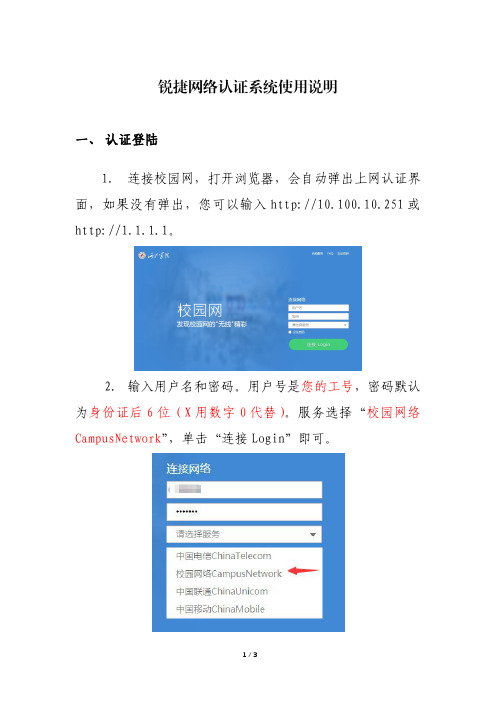
1.连接校园网,打开浏览器,会自动弹出上网认证界面,如果没有弹出,您可以输入http://10.100.10.251或http://1.1.1.1。
2.输入用户名和密码。
用户号是您的工号,密码默认为身份证后6位(X用数字0代替)。
服务选择“校园网络CampusNetwork”,单击“连接Login”即可。
二、密码修改
登陆后,单击界面左上角的“自动服务”,再找到“密码修改”链接,修改密码即可。
密码应具有一定的复杂度,并保管好密码。
三、密码重置
方法一:自助找回。
您事先要在自助服务平台(http://10.100.10.250:8080)上的安全中心登记您的邮箱,在忘记密码时就可以在登录界面使用“找回密码”功能,自行重置密码。
方法二:持身份证等有效证件到东区逸夫楼608现代教育技术中心办公室办理重置手续。
锐捷网络 RG-ES 系列交换机 ESW_1.0(1)B1P20 Web 管理手册说明书
RG-ES系列交换机文档版本V1.0归档日期2022-08-27版权声明copyright © 2022 锐捷网络保留对本文档及本声明的一切权利。
未得到锐捷网络的书面许可,任何单位和个人不得以任何方式或形式对本文档的部分或全部内容进行复制、摘录、备份、修改、传播、翻译成其他语言、将其部分或全部用于商业用途。
、、和其他锐捷网络商标均为锐捷网络的商标。
本文档提及的其他所有商标或注册商标,由各自的所有人拥有。
免责声明您所购买的产品、服务或特性等应受商业合同和条款的约束,本文档中描述的部分或全部产品、服务或特性可能不在您的购买或使用范围之内。
除非合同另有约定,锐捷网络对本文档内容不做任何明示或默示的声明或保证。
由于产品版本升级或其他原因,本文档内容会不定期进行更新。
锐捷网络保留在没有任何通知或者提示的情况下对文档内容进行修改的权利。
本手册仅作为使用指导。
锐捷网络在编写本手册时已尽力保证其内容准确可靠,但并不确保手册内容完全没有错误或遗漏,本手册中的所有信息也不构成任何明示或暗示的担保。
前言读者对象本书适合下列人员阅读⚫网络工程师⚫技术推广人员⚫网络管理员技术支持⚫锐捷睿易官方网站:https:///⚫锐捷睿易在线客服:https:///?p=smb⚫锐捷网络官方网站服务与支持版块:https:///service.aspx⚫7天无休技术服务热线:4001-000-078⚫常见问题搜索:https:///service/know.aspx⚫锐捷睿易技术支持与反馈信箱:*********************.cn⚫锐捷网络文档支持与反馈信箱:**************.cn⚫锐捷网络服务公众号:【锐捷服务】扫码关注本书约定1. 图形界面格式约定界面图标解释举例<>按钮<确定>[]菜单项,弹窗名称,页面名称,标签页的名称菜单项“系统设置”可简化[系统设置] >>分级页面,子菜单项选择[系统设置]>>[系统管理员]“”配置项,提示信息,链接如提示框提示“保存配置成功”点击“开启”选项点击“忘记密码”链接2. 各类标志本书还采用各种醒目标志来表示在操作过程中应该特别注意的地方,这些标志的意义如下:警告表示用户必须严格遵守的规则。
TP-Link R系列企业级路由器主要功能配置实例说明书

声明Copyright © 2021 普联技术有限公司版权所有,保留所有权利未经普联技术有限公司明确书面许可,任何单位或个人不得擅自仿制、复制、誊抄或转译本手册部分或全部内容,且不得以营利为目的进行任何方式(电子、影印、录制等)的传播。
为普联技术有限公司注册商标。
本手册提及的所有商标,由各自所有人拥有。
本手册所提到的产品规格和资讯仅供参考,如有内容更新,恕不另行通知。
除非有特殊约定,本手册仅作为使用指导,所作陈述均不构成任何形式的担保。
目录第1章前言 (1)1.1 目标读者 (1)1.2 本书约定 (1)1.3 适用机型 (1)第2章基础联网设置 (3)2.1 企业路由器基本设置指南 (3)2.1.1 应用介绍 (3)2.1.2 需求介绍 (3)2.1.3 设置方法 (3)2.1.4 注意事项 (7)2.2 企业路由器IPv6上网配置指导 (8)2.2.1 应用介绍 (8)2.2.2 需求介绍 (8)2.2.3 设置方法 (8)2.2.4 疑问解答 (15)第3章设备管理 (17)3.1 如何在外网远程管理(控制)路由器? (17)3.1.1 应用介绍 (17)3.1.2 需求介绍 (17)3.1.3 设置方法 (17)3.1.4 注意事项 (20)3.1.5 疑问解答 (21)3.2 如何设置自动重启? (22)3.2.1 应用介绍 (22)3.2.2 需求介绍 (22)3.2.3 设置方法 (22)3.2.4 注意事项 (23)第4章负载均衡 (24)4.1 多WAN口路由器负载均衡的设置指南 (24)4.1.1 应用介绍 (24)4.1.2 需求介绍 (24)4.1.3 工作原理 (24)4.1.4 设置方法 (25)第5章路由转发模块 (27)5.1 策略路由设置指南 (27)5.1.1 应用介绍 (27)5.1.2 需求介绍 (27)5.1.3 设置方法 (28)5.1.4 疑问解答 (31)5.2 ISP选路设置指南 (33)5.2.1 应用介绍 (33)5.2.2 需求介绍 (33)5.2.3 设置方法 (34)5.3 静态路由设置指南 (36)5.3.1 应用介绍 (36)5.3.2 需求介绍 (36)5.3.3 设置方法 (37)5.4 线路备份设置指南 (38)5.4.1 应用介绍 (38)5.4.2 需求介绍 (38)5.4.3 设置方法 (38)5.4.4 注意事项 (40)5.5 虚拟服务器设置指南 (41)5.5.1 应用介绍 (41)5.5.2 需求介绍 (41)5.5.3 设置方法 (42)5.5.4 疑问解答 (43)5.6 NAT-DMZ功能设置指南 (44)5.6.1 应用介绍 (44)5.6.2 需求介绍 (44)5.6.3 设置方法 (45)第6章AP和易展管理 (47)6.1 AP管理设置指南 (47)6.1.1 应用介绍 (47)6.1.2 需求介绍 (47)6.1.3 设置方法 (47)6.2 易展AP设置指南 (53)6.2.1 应用介绍 (53)6.2.2 需求介绍 (53)6.2.3 设置方法 (54)6.2.4 注意事项 (58)第7章行为管控 (59)7.1 连接数限制设置指南 (59)7.1.1 应用介绍 (59)7.1.2 需求介绍 (59)7.1.3 设置方法 (59)7.1.4 疑问解答 (60)7.2 访问控制设置指南 (61)7.2.1 应用介绍 (61)7.2.2 需求介绍 (61)7.2.3 设置方法 (61)7.2.4 疑问解答 (67)7.3 应用限制设置指南 (68)7.3.1 应用介绍 (68)7.3.2 需求介绍 (68)7.3.3 设置方法 (68)7.4 网址过滤设置指南 (71)7.4.1 应用介绍 (71)7.4.2 需求介绍 (71)7.4.3 设置方法 (71)7.4.4 疑问解答 (75)7.5 网页安全设置指南 (76)7.5.1 应用介绍 (76)7.5.2 需求介绍 (76)7.5.3 设置方法 (76)第8章安全防护 (78)8.1 ARP防护设置指南 (78)8.1.1 应用介绍 (78)8.1.2 需求介绍 (78)8.1.3 设置方法 (78)8.1.4 疑问解答 (84)8.2 MAC地址过滤设置指南 (86)8.2.1 应用介绍 (86)8.2.2 需求介绍 (86)8.2.3 设置方法 (86)第9章VPN模块 (88)9.1 IPSec VPN设置指南 (88)9.1.1 应用介绍 (88)9.1.2 需求介绍 (88)9.1.3 设置方法 (89)9.2 L2TP VPN设置指南 (96)9.2.1 应用介绍 (96)9.2.2 需求介绍 (96)9.2.3 设置方法 (97)9.3 PPTP VPN设置指南 (105)9.3.1 应用介绍 (105)9.3.2 需求介绍 (105)9.3.3 设置方法 (106)9.4 L2TP VPN代理上网设置指南 (115)9.4.1 应用介绍 (115)9.4.2 需求介绍 (115)9.4.3 设置方法 (115)9.5 PPTP VPN代理上网设置指南 (120)9.5.1 应用介绍 (120)9.5.2 需求介绍 (120)9.5.3 设置方法 (120)第10章认证管理 (125)10.1 一键上网设置指南 (125)10.1.1 应用介绍 (125)10.1.2 需求介绍 (125)10.1.3 设置方法 (126)10.2 短信认证设置指南 (130)10.2.1 应用介绍 (130)10.2.2 需求介绍 (130)10.2.3 设置方法 (131)10.3 Portal认证设置指南—使用内置WEB服务器和内置认证服务器 (136)10.3.1 应用介绍 (136)10.3.2 需求介绍 (136)10.3.3 设置方法 (137)10.4 Portal认证设置指南—使用内置WEB服务器和外部认证服务器 (141)10.4.1 应用介绍 (141)10.4.2 需求介绍 (141)10.4.3 设置方法 (142)10.5 Portal认证设置指南—使用外置WEB服务器和内置认证服务器 (146)10.5.1 应用介绍 (146)10.5.2 需求介绍 (146)10.5.3 设置方法 (147)10.6 Portal认证设置指南—使用外置WEB服务器和外置认证服务器 (150)10.6.1 应用介绍 (150)10.6.2 需求介绍 (150)10.6.3 设置方法 (151)10.7 免认证策略的使用方法 (154)10.7.1 应用介绍 (154)10.7.2 需求介绍 (154)10.7.3 设置方法 (155)10.8 Portal认证中,外部WEB服务器建立规范 (158)10.8.1 应用介绍 (158)10.8.2 流程规范 (159)第11章工业级特性 (163)11.1 如何使用工业级路由器? (163)11.1.1 产品介绍 (163)11.1.2 需求介绍 (163)11.1.3 设置方法 (164)第12章其它功能 (168)12.1 地址组的设置与管理 (168)12.1.1 应用介绍 (168)12.1.2 需求介绍 (168)12.1.3 设置方法 (168)12.1.4 疑问解答 (170)12.2 带宽控制设置指南 (172)12.2.1 应用介绍 (172)12.2.2 需求介绍 (172)12.2.3 设置方法 (172)12.2.4 疑问解答 (175)12.3 PPPOE服务器应用设置指南 (177)12.3.1 应用介绍 (177)12.3.2 需求介绍 (177)12.3.3 设置方法 (178)12.3.4 疑问解答 (181)12.4 网络唤醒功能使用指南 (183)12.4.1 应用介绍 (183)12.4.2 需求介绍 (183)12.4.3 设置方法 (183)12.5 诊断工具使用指南 (186)12.5.1 应用介绍 (186)12.5.2 需求介绍 (186)12.5.3 设置方法 (187)第1章前言本手册旨在帮助您正确使用R系列企业级路由器。
锐捷网络 RG-EG 系列出口网关 说明书

密级:受控发行说明RG-EG系列出口网关RGOS 10.3(4b7), Release(98250)正式版本版权声明福建星网锐捷网络有限公司©2000-2010版权所有,保留一切权利。
没有经过本公司书面许可,任何单位和个人不得擅自摘抄、复制本书内容的部分或者全部,并且不得以任何形式传播。
、、、、、、、、、、都是福建星网锐捷网络有限公司的注册商标,不得仿冒。
前言本文记录了RG-EG系列出口网关RGOS10.3(4b7), Release(98250)版本的信息,内容包括:关于本文的任何疑问,请咨询锐捷网络技术支持热线:4008-111-000 。
目录1基本信息 (5)2硬件特性 (5)2.1支持的硬件 (5)2.2硬件限制 (5)3软件特性 (6)3.1解决问题 (6)3.2新增功能 (6)3.3功能变更 (7)3.4软件限制 (7)4配套手册 (7)5升级说明 (8)5.1升级文件清单 (8)5.2TFTP远程升级 (8)5.3Xmoderm本地升级 (9)5.4升级注意事项 (9)5.5HTTP升级主程序 (10)5.6HTTP升级URL库 (11)1 基本信息2 硬件特性2.1 支持的硬件该版本支持的硬件有:2.2 硬件限制无3 软件特性3.1 解决问题为新产品发布的正式版本。
没有遗留问题。
3.2 新增功能在基线版本的基础上新增以下功能:3.3 功能变更为新产品发布的正式版本。
无功能变更。
3.4 软件限制其他限制:4 配套手册该版本适用的产品用户手册如下:以上产品用户手册可从锐捷网络技术支持网站下载:/ 。
5升级说明5.1升级文件清单本系列产品可以使用Tftp 或者xmodem 将升级文件传输到设备上。
传输成功后,重新启动设备,升级文件就会自动完成当前系统的检测和升级。
5.2 TFTP 远程升级可以通过TFTP 方式进行出口网关软件的远程升级,具体步骤如下:5.3 Xmoderm本地升级可以通过Xmoderm方式进行出口网关软件的本地升级,具体步骤如下:5.4 升级注意事项在对该版本进行升级的过程中,请注意以下事项:1. 在升级或者自动升级过程中,会有不允许重启的提示,一旦出现类似提示,请务必不要断电或者复位系统,也不要随便插拔其他模块。
宇视科技(uniview)供应商Green Portal操作指南

“产品分类”填写操作指南
操作指南——“产品分类” 类别
1 单击左侧菜单,在右侧主界面会出现相应的“产品分类” 列表
2 单击型号前的小三角符号,展开后,可以看到 “第三方环保检测报告文件夹”
2-1 双击“第三方环保检测报告文件夹”,即可打开文件夹上传列表 上传资料:点击“+选择文件”选择上传的环保资料→点击“上传” 或者“上传全部” → 上传进度条会进行加载→Status显示“√”,即表示上传成功→点击“保存” 即可, 关掉窗口后将会在文件下看到已上传的文件;若文件上传错误,选中相应文件,点击“删除文件”,将立即删除 注:由于在“产品分类”的厂家,给我司供的物料繁多,但是组成大致相同,则按类别管理,贵司上传物料所有涉及的原材料的环保资料即可。
2-1-6 保存RoHS调查表:调查表中的必填项均需要填写,填写完整后,点击右下角的“保存”即可保存该调查表,保存后跳出提示框表示已保存完成;
操作指南——“厂家型号” 类别(续)
2-2 双击“REACH调查表”,即可展开REACH调查表,目前REACH调查表由“1.供应商信息”、“2.物料信息”、“3.符合性信息”、“4.物质信 息”四个部分组成
周期:以出报告的日期开始进行计算,一年内有效,超过一年需要重新送测,请贵司安排好报告之间的衔接;
宇视要求:目前我司强制要求产品符合RoHS 10。 贵司可以提供①一年有效期内的第三方RoHS报告;
②贵司按体系管控出具的符合RoHS的自我声明; ③贵司出具物料组成清单及各组分的RoHS 10环保资料;
②报告的有效期为一年,以出报告的时间进行计算,往后一年为有效期,请贵司安排好报告的衔接时间; ③RoHS10报告或声明为必须项;若贵司是通过原材料管控或者体系管控,请附上物料的组成报告或者相应的自我声明,如下图的“组成报告清单”+“各组成报告”;
基于锐捷无线设备的酒店网络升级方案设计

基于锐捷无线设备的酒店网络升级方案设计徐俊梅,孔星星(合肥科技职业学院电子信息系,安徽合肥230088)摘要:本方案主要是针对酒店早期设计的无线网络进行升级和优化,具体体现在覆盖率提高,无线信号强度提升,对于使用频率较高的位置及盲点位置,要在不同的区域使用不同的方式进行部署安装,满足不同场合所需求,达到最优的体验效果,同时要保障整个网络和入网用户的安全。
主要体现在:1)保证无线覆盖区域内的信号强度,重点保证客房,餐厅,休息区等区域的无线信号强度;2)保证覆盖区域内无线使用效果,要考虑无线信号干扰、无线漫游等;3)重点考虑使用频率较高的公共区域的覆盖效果;4)为避免单点故障,可以使用集群技术AC-1为主用,AC-2为备用,以此进行冗余设计;5)启用Web认证;6)网络安全,锐捷ARP欺骗防范技术。
关键词:无线网络;覆盖率;冗余;无线AC;无线AP;升级优化;安全中图分类号:TP391文献标识码:A文章编号:1009-3044(2021)13-0055-04开放科学(资源服务)标识码(OSID):旅游、商务活动、大型体育比赛等因素带动了酒店业近年来的快速发展。
现在的酒店,提供宽带上网已经是基本服务。
客户期待着通过酒店带宽网络实现更多的应用:远程办公、网络视频会议、文件快传、享受视频点播、使用酒店特色的信息资源等等。
这些需求对酒店服务领域的要求很高,但同时也为酒店的收益提供了机会。
服务水平的提高,是酒店行业加强自身建设的重中之重,而随着来自各地商务客户的增加,以及正常生活往来对网络的依赖性,能否提供优质的网络服务成为客户入住的必要考虑因素,因而酒店必须加强优化自己的网络服务。
这样,一方面提升了现代化酒店的服务与管理水平,同时,也为酒店经营者带来了相应的利益,消费者也享受到优质的服务。
1建设需求和设计原则1.1背景ZG酒店业务不断发展壮大,员工数量快速增长。
为了更好管理数据,提供服务,公司决定建设新的网络服务平台。
- 1、下载文档前请自行甄别文档内容的完整性,平台不提供额外的编辑、内容补充、找答案等附加服务。
- 2、"仅部分预览"的文档,不可在线预览部分如存在完整性等问题,可反馈申请退款(可完整预览的文档不适用该条件!)。
- 3、如文档侵犯您的权益,请联系客服反馈,我们会尽快为您处理(人工客服工作时间:9:00-18:30)。
1
产品概述
锐捷网络RG-ePortal是一套网络身份准入的门户系统,可以配合锐捷的认证计费系统SAM、或者安全管理平台SMP进行基于web方式的身份认证或者域的划分和认证。
传统的网络身份认证都是基于802.1X模式进行,这种方式控制粒度精细,但是由于对于交换机有要求,而且还要求用户安装客户端程序。
这种模式的应用有一定的设备要求,而且部署相对比较麻烦,维护量大,针对这种情况,锐捷开发了RG-ePortal这套产品,来解决以上的问题。
一个方面可以解决复杂的部署,另一个方面用户无需安装客户端,直接通过浏览器就可以进行认证,提高了用户的应用满意度。
目前RG-ePortal这款产品,融合在锐捷的两个解决方案中,一个是iSAM解决方案,另一个是安全域解决方案。
2.1 iSAM解决方案中的ePortal
2.1.1 web准入方案
产品包装效果图
这种模式是锐捷的接入交换机、ePortal系统和SAM系统配合,进行基于web的准入认证和计费。
不仅降低了部署的难度,提高了应用性,而且这种模式还具有很高的安全性,将网络的认证部署在了网络的边缘,全面满足了
内网访问的安全需要。
2.1.2 web准出方案
由于不少的学校存在多种网络设备厂商的接入设备,如果完全进行基于802.1X认证有一定的困难。
特别是对于办公网或者家属区等区域,安全的要求不是很高。
那么可以通过SAM、出口网关设备ACE、ePortal的组合,进行网络的准出认证。
一个方面减少了安装客户端的麻烦,可以基于浏览器进行基于web的认证,同时保护了原有设备资产的投入,无需大批的更新设备。
但是这种解决方案有一定的缺陷,就是网关是部署在出口,对于内网的资源访问安全控制做得不是很到位。
这种模式最好和准入认证结合起来用,会有比较好的效果。
2.2 安全域解决方案中的ePortal
2.2.
1 防火墙板卡控制模式
2
3
对于政府办公局域网,需要进行安全域的划分和业务区域的隔离和授权。
针对这种用户场景,如果又无法通过802.1X的模式来部署,推荐采用web的方式进行域的身份认证。
这种模式通过SMP 、防火墙板卡和ePortal结合的方式,实现了基于web 的域访问控制,用户可以通过浏览器来进行访问域的选择和认证。
2.2.2 路由器控制模式
电子政务外网的服务器资源也需要按照相应的要求进行安全域的划分,用户如果需要访问相应的资源,首先需要进行安全域的认证。
这种基于域的访问控制可以通过SMP 、路由器和ePortal组合的方式来满足需要。
SMP作为策略控制器,控制和下发用户的安全域策略,路由器进行执行,ePortal系统作为web服务器存在,用户无需安装客户端,通过浏览器的方式进行访问域的选择和身份认证。
产品特性
◆
系统采用B/S架构设计,具有很好的人机交互界面和易用性;◆ 支持高可用集群技术,可以有效地解决单服务器的性能限制,实现故障的快速转移,保证服务的高可用性以及灵活的扩展性;
◆
支持和接入交换机进行基于web的准入认证;◆
支持和网关设备的配合,进行web的准出认证;◆
支持和防火墙板卡、路由器基于域的划分和认证;◆
支持保活功能,可以实时探测用户页面的存活;◆ 支持页面的定制,
可以进行用户登录页面的自定义;
◆ 支持portal服务器的性能监控;
◆ 支持portal服务器的安全控制,只有管理者才可以访问相应的portal服务器;
◆ Portal服务器的攻击检测,可以记录攻击portal服务器的ip地址和次数。
技术参数
硬件配置
系统配置
标准版、企业版、专业版:
性能参数
4
5。